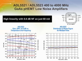
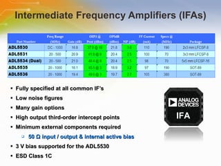
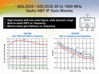
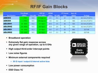
RF/IF Amplifier Product Overview Source: ANALOG DEVICES
Introduction Purpose To introduce ADI’s RF/IF Amplifier products and their benefits Outline Overview of RF/IF Amplifier portfolio Low Noise Amplifiers Intermediate Frequency Amplifiers Driver Amplifiers Gain Blocks Content 19 pages
State of the art performance Specified for broad and narrowband applications Shortens TTM Eases device selection Lowers manufacturing costs Simplifies component evaluation Streamlines supply chain and logistics  New RF/IF amps complement ADI’s RF IC portfolio Supports any RX/TX signal path Addresses any radio architecture and any air interface standard ADI’s RF/IF Amplifier Portfolio Benefits RF/IF Amplifiers Complete the RF Signal Chain Available from ADI
ADI’s RF/IF Amplifiers Performance and Features World class performance across complete portfolio Optimized for the highest linearity applications Available in the SOT-89 and in the smallest footprint packaging Internal active bias Internal matching Designed to highest levels of ESD sensitivity Fully characterized across temperature, supply, frequency Datasheets are fully specified; reduces cost, time Minimizes need for device characterization by design engineers; speeds design process Reduces use of external tuning components, cost, space
Low Noise Amplifiers (LNA’s) Broadband operation Low noise figure of 0.8 dB Including external match High gain of 21.5 dB High output third-order intercept points Low power consumption Minimum external tuning components required Internal active bias 3 V bias is supported for each LNA Current consumption down to 30 mA, or lower ESD Class 1A World-class LNA’s Offer Unprecedented Performance, Flexibility LNA
ADL5521 / ADL5523 400 to 4000 MHz GaAs pHEMT Low Noise Amplifiers High linearity with 0.8 dB NF on just 60 mA ADL5523 Gain, OIP3, & P1dB vs.  Temperature and Frequency ADL5523 Distribution of Noise Figure for Multiple Parts
Intermediate Frequency Amplifiers (IFAs) Fully   specified   at   all   common   IF’s Low   noise   figures Many   gain   options High   output   third-order   intercept   points Minimum   external   components   required 50   Ω   input   /   output   &   internal   active   bias 3   V   bias   supported   for   the   ADL5530 ESD   Class   1C IFA
ADL5535 / ADL5536 20 to 1000 MHz GaAs HBT IF Gain Blocks ADL5535 Gain, OIP3 and P1dB vs. Frequency ADL5535 Gain vs. Frequency and Temperature High linearity with low noise figure, wide dynamic range Best-in-class OIP3 vs. frequency Best-in-class gain flatness vs. frequency
Circuits From The Lab (CFTL)  www.analog.com/rfamps
Driver Amplifiers Narrow and broadband specific products High output third-order intercept points High output compression points Minimum external tuning components required Internal active bias Very low power consumption ESD Class 3A Drivers
ADL5320 (400 to 2700 MHz)  /  ADL5321 (2300 to 4000 MHz) GaAs HBT 1/4 W RF Driver Amplifiers Excellent ACPR performance High OIP3 and P1dB with very low current consumption ADL5320 WCDMA ACPR vs. POUT at 2140 MHz 3GPP 3.5 TM1-64 ADL5320 OIP3 vs. POUT and Frequency 2060 to 2200 MHz
1 W Driver Amplifier Broadband amplifier High output third-order intercept point High output compression point Low noise figure Minimum external tuning components required Internal active bias Very low power consumption Small 4 mm x 4mm LFCSP package size Fast power-down/up time of 50 ns ESD Class 1C Drivers
ADL5604 700 to 2700 MHz GaAs HBT 1 W RF Driver Amplifier Excellent ACPR performance Low current consumption of just 318 mA WCDMA ACPR over Frequency 3GPP 3.5 TM1-64
RF/IF Gain Blocks Broadband   operation Extremely   flat   gain   response   across any   given   range   of   operation,   up   to   6   GHz High   output   third-order   intercept   points Low   noise   figures Minimum   external   components   required 50   Ω   input   /   output   &   Internal   active   bias Low   power   consumption ESD   Class   1C Gain Blocks
ADL5541 / ADL5542 50 MHz to 6 GHz GaAs HBT RF/IF Gain Blocks These gain blocks have higher linearity at higher frequencies than the competition Compact 3 mm x 3 mm LFCSP packaging ADL5541 Gain, Noise Figure, OIP3 and P1dB vs. Frequency  ADL5541 Input / Output Return Loss and Reverse Isolation vs. Frequency
ADL5601 / ADL5602 50 MHz to 4 GHz GaAs HBT RF/IF Gain Blocks The highest dynamic range gain blocks on the market, providing extremely low noise figures and very high OIP3 specifications simultaneously   ADL5602 OIP3 vs. Frequency and Output Power ADL5602 Noise Figure vs. Frequency & Temp
Product Portfolio RF Amplifiers Click to get the Latest Brochure RF/IF Amps Product Frequency Range (MHz) Gain (dB) Supply Current (mA) Packaging Low Noise Amplifiers (LNA) ADL5521 400 to 4000 20.8 60 3x3 mm LFCSP-8 ADL5523 400 to 4000 21.5 60 3x3 mm LFCSP-8 Intermediate Frequency Amplifiers (IFA) ADL5530 dc to 1000 16.8 110 3x3 mm LFCSP-8 ADL5531 20 to 500 20.9 100 3x3 mm LFCSP-8 ADL5534 (Dual) 20 to 500 21 98 5x5 mm LFCSP-16 ADL5535 20 to 1000 16.1 97 SOT-89 ADL5536 20 to 1000 19.4 105 SOT-89 Driver Amplifiers ADL5320 400 to 2700 13.7 104 SOT-89 ADL5321 2300 to 4000 14 90 SOT-89 ADL5322 700 to 1000 19.9 320 3x3 mm LFCSP-8 ADL5323 1700 to 2400 19.5 320 3x3 mm LFCSP-8 ADL5604 700 to 2700 12.2 318 4x4 mm LFCSP-16 Gain Blocks ADL5541 50 to 6000 14.7 90 3x3 mm LFCSP-8 ADL5542 50 to 6000 18.7 93 3x3 mm LFCSP-8 ADL5601 50 to 4000 15 83 SOT-89 ADL5602 50 to 4000 19.5 89 SOT-89
Evaluation Board Details Which Amplifiers Require Which External Components EVB Showing External Decoupling (ADL5541) RF Amplifiers Requiring Only External Decoupling: ADL5530 / 31 / 34 / 35 / 36 IFAs ADL5322 / 23 Drivers AD8353 / 54 Gain Blocks ADL5541 / 42 Gain Blocks ADL5601 / 02 Gain Blocks EVB Showing External Tuning (ADL5320) RF Amplifiers Requiring Minimal External Tuning: ADL5521 / 23 LNAs ADL5320 / 21 Drivers ADL5604 Driver
Additional Resource For ordering ADI RF/IF Amplifiers, please click the parts list link or Call our sales hotline For more product information go to www.analog.com/rfamps Visit Element 14 to post your question   www.element-14.com For additional inquires contact our technical service hotline or even use our “Live Technical Chat” online facility Newark Farnell

RF/IF Amplifier Product Overview

  • 1.
    RF/IF Amplifier ProductOverview Source: ANALOG DEVICES
  • 2.
    Introduction Purpose Tointroduce ADI’s RF/IF Amplifier products and their benefits Outline Overview of RF/IF Amplifier portfolio Low Noise Amplifiers Intermediate Frequency Amplifiers Driver Amplifiers Gain Blocks Content 19 pages
  • 3.
    State of theart performance Specified for broad and narrowband applications Shortens TTM Eases device selection Lowers manufacturing costs Simplifies component evaluation Streamlines supply chain and logistics New RF/IF amps complement ADI’s RF IC portfolio Supports any RX/TX signal path Addresses any radio architecture and any air interface standard ADI’s RF/IF Amplifier Portfolio Benefits RF/IF Amplifiers Complete the RF Signal Chain Available from ADI
  • 4.
    ADI’s RF/IF AmplifiersPerformance and Features World class performance across complete portfolio Optimized for the highest linearity applications Available in the SOT-89 and in the smallest footprint packaging Internal active bias Internal matching Designed to highest levels of ESD sensitivity Fully characterized across temperature, supply, frequency Datasheets are fully specified; reduces cost, time Minimizes need for device characterization by design engineers; speeds design process Reduces use of external tuning components, cost, space
  • 5.
    Low Noise Amplifiers(LNA’s) Broadband operation Low noise figure of 0.8 dB Including external match High gain of 21.5 dB High output third-order intercept points Low power consumption Minimum external tuning components required Internal active bias 3 V bias is supported for each LNA Current consumption down to 30 mA, or lower ESD Class 1A World-class LNA’s Offer Unprecedented Performance, Flexibility LNA
  • 6.
    ADL5521 / ADL5523400 to 4000 MHz GaAs pHEMT Low Noise Amplifiers High linearity with 0.8 dB NF on just 60 mA ADL5523 Gain, OIP3, & P1dB vs. Temperature and Frequency ADL5523 Distribution of Noise Figure for Multiple Parts
  • 7.
    Intermediate Frequency Amplifiers(IFAs) Fully specified at all common IF’s Low noise figures Many gain options High output third-order intercept points Minimum external components required 50 Ω input / output & internal active bias 3 V bias supported for the ADL5530 ESD Class 1C IFA
  • 8.
    ADL5535 / ADL553620 to 1000 MHz GaAs HBT IF Gain Blocks ADL5535 Gain, OIP3 and P1dB vs. Frequency ADL5535 Gain vs. Frequency and Temperature High linearity with low noise figure, wide dynamic range Best-in-class OIP3 vs. frequency Best-in-class gain flatness vs. frequency
  • 9.
    Circuits From TheLab (CFTL) www.analog.com/rfamps
  • 10.
    Driver Amplifiers Narrowand broadband specific products High output third-order intercept points High output compression points Minimum external tuning components required Internal active bias Very low power consumption ESD Class 3A Drivers
  • 11.
    ADL5320 (400 to2700 MHz) / ADL5321 (2300 to 4000 MHz) GaAs HBT 1/4 W RF Driver Amplifiers Excellent ACPR performance High OIP3 and P1dB with very low current consumption ADL5320 WCDMA ACPR vs. POUT at 2140 MHz 3GPP 3.5 TM1-64 ADL5320 OIP3 vs. POUT and Frequency 2060 to 2200 MHz
  • 12.
    1 W DriverAmplifier Broadband amplifier High output third-order intercept point High output compression point Low noise figure Minimum external tuning components required Internal active bias Very low power consumption Small 4 mm x 4mm LFCSP package size Fast power-down/up time of 50 ns ESD Class 1C Drivers
  • 13.
    ADL5604 700 to2700 MHz GaAs HBT 1 W RF Driver Amplifier Excellent ACPR performance Low current consumption of just 318 mA WCDMA ACPR over Frequency 3GPP 3.5 TM1-64
  • 14.
    RF/IF Gain BlocksBroadband operation Extremely flat gain response across any given range of operation, up to 6 GHz High output third-order intercept points Low noise figures Minimum external components required 50 Ω input / output & Internal active bias Low power consumption ESD Class 1C Gain Blocks
  • 15.
    ADL5541 / ADL554250 MHz to 6 GHz GaAs HBT RF/IF Gain Blocks These gain blocks have higher linearity at higher frequencies than the competition Compact 3 mm x 3 mm LFCSP packaging ADL5541 Gain, Noise Figure, OIP3 and P1dB vs. Frequency ADL5541 Input / Output Return Loss and Reverse Isolation vs. Frequency
  • 16.
    ADL5601 / ADL560250 MHz to 4 GHz GaAs HBT RF/IF Gain Blocks The highest dynamic range gain blocks on the market, providing extremely low noise figures and very high OIP3 specifications simultaneously ADL5602 OIP3 vs. Frequency and Output Power ADL5602 Noise Figure vs. Frequency & Temp
  • 17.
    Product Portfolio RFAmplifiers Click to get the Latest Brochure RF/IF Amps Product Frequency Range (MHz) Gain (dB) Supply Current (mA) Packaging Low Noise Amplifiers (LNA) ADL5521 400 to 4000 20.8 60 3x3 mm LFCSP-8 ADL5523 400 to 4000 21.5 60 3x3 mm LFCSP-8 Intermediate Frequency Amplifiers (IFA) ADL5530 dc to 1000 16.8 110 3x3 mm LFCSP-8 ADL5531 20 to 500 20.9 100 3x3 mm LFCSP-8 ADL5534 (Dual) 20 to 500 21 98 5x5 mm LFCSP-16 ADL5535 20 to 1000 16.1 97 SOT-89 ADL5536 20 to 1000 19.4 105 SOT-89 Driver Amplifiers ADL5320 400 to 2700 13.7 104 SOT-89 ADL5321 2300 to 4000 14 90 SOT-89 ADL5322 700 to 1000 19.9 320 3x3 mm LFCSP-8 ADL5323 1700 to 2400 19.5 320 3x3 mm LFCSP-8 ADL5604 700 to 2700 12.2 318 4x4 mm LFCSP-16 Gain Blocks ADL5541 50 to 6000 14.7 90 3x3 mm LFCSP-8 ADL5542 50 to 6000 18.7 93 3x3 mm LFCSP-8 ADL5601 50 to 4000 15 83 SOT-89 ADL5602 50 to 4000 19.5 89 SOT-89
  • 18.
    Evaluation Board DetailsWhich Amplifiers Require Which External Components EVB Showing External Decoupling (ADL5541) RF Amplifiers Requiring Only External Decoupling: ADL5530 / 31 / 34 / 35 / 36 IFAs ADL5322 / 23 Drivers AD8353 / 54 Gain Blocks ADL5541 / 42 Gain Blocks ADL5601 / 02 Gain Blocks EVB Showing External Tuning (ADL5320) RF Amplifiers Requiring Minimal External Tuning: ADL5521 / 23 LNAs ADL5320 / 21 Drivers ADL5604 Driver
  • 19.
    Additional Resource Forordering ADI RF/IF Amplifiers, please click the parts list link or Call our sales hotline For more product information go to www.analog.com/rfamps Visit Element 14 to post your question www.element-14.com For additional inquires contact our technical service hotline or even use our “Live Technical Chat” online facility Newark Farnell

Editor's Notes

  • #2 Welcome to the training module on RF/IF amplifiers from Analog Devices.
  • #3 This training module will introduce ADI’s RF/IF amplifier products and their benefits.
  • #4 RF/IF amplifiers complete the RF signal chain available from ADI. The amplifier family has state of the art performance in that there are parts specified for both broad and narrowband applications, which shortens time to market, eases device selection by designers, lowers manufacturing costs, and simplifies component evaluation. Which all help streamline supply chain management and logistics. The RF/IF amplifiers complete ADIs RF IC portfolio by supporting any RX/TX signal path, and addresses any radio architecture and air interface standard.
  • #5 The entire RF/IF amplifier family has world class performance. The amplifiers are optimized for the highest linearity applications, and are available in the industry standard SOT-89 package as well as in the smallest footprint packaging. Every amplifier has an internal active bias, and most amplifiers include internal matching. The amplifiers are designed to meet the highest levels of ESD sensitivity. Each amplifier is fully characterized across temperature, power supply variation, and frequency. Fully specified datasheets help reduce design cost and time by minimizing the need for device characterization by design engineers, which speeds the design process. The amplifier designs also focus on reducing external components to further reduce cost and space.
  • #6 The first family of amplifiers we’ll introduce are the low noise amplifiers (LNAs), which offer unprecedented performance and flexibility. The ADL5521 and ADL5523 offer broadband operation from 400 MHz to 4 GHz. The ADL5523 provides the low noise figure of 0.8 dB, which includes the two component external match, while accomplishing a high gain of 21.5 dB. Both LNAs have an adjustable bias which can be optimized for 3 V to 5 V operation, and supply current from 60 mA to 30 mA, or lower. Their datasheets characterize the LNA over frequency at two bias points, 5 V / 60 mA and 3 V / 30 mA.
  • #7 The ADL5523 offers high linearity with 0.8 dB noise figure on just 60 mA. The graph on the left shows the detail our datasheets go into for gain, OIP3, and P1dB vs. temperature and frequency. The graph on the right shows noise figure distribution for multiple parts.
  • #8 The next amplifier family is the intermediate frequency amplifiers (IFAs). These amplifiers are optimized for the low frequency range of 20 MHz up to 1 GHz. Each IFA is fully specified in the datasheet at all the common IFs. The IFA family also provides extremely high dynamic range by achieving very low noise figures, and very high OIP3s simultaneously over frequency. The IFAs require few external components since the amplifiers are internally matched to 50 Ω at the input and output, and have an internal active bias.
  • #9 The ADL5535 and ADL5536 SOT-89 IFAs have a very wide dynamic range. These IFAs also provide best-in-class OIP3 vs. frequency, and best-in-class gain flatness vs. frequency. The graph on the left shows gain, OIP3, and P1dB performance vs. frequency, and the graph on the right shows gain vs. frequency and temperature for the ADL5535.
  • #10 The ADL5534 dual IFA is featured in a Circuits from the Lab article that shows how the IFA can be used as a high performance fixed gain ADC driver. Please visit www.analog.com/rfamps to download the entire article.
  • #11 ADIs driver amplifier family offers products specified for both narrow and broadband operation. The ADL5320 and ADL5321 SOT-89 1/4 W drivers operate across 400 MHz to 2.7 GHz, and 2.3 GHz to 4 GHz respectively. The 1/4 W drivers provide very high OIP3 and P1dB specifications on very low power consumptions. While the internally matched ADL5322 and ADL5323 1/2 W drivers operate across 700 MHz to 1 GHz, and 1.7 GHz to 2.4 GHz respectively in a compact 3x3 mm LFCSP package.
  • #12 The ADL5320 driver amplifier achieves excellent ACPR performance. At an output power of 10 dBm the ACPR is still very low at −70 dBc, making the device particularly suitable for PA driver applications. The ADL5320 also provides 42 dBm of OIP3 and 25.7 dBm of P1dB at 2.14 GHz on only 104 mA.
  • #13 ADIs newest driver amplifier is the ADL5604 1 W. At 2.63 GHz the ADL5604 achieves a gain of 12.2 dB, and an OIP3 of 42.2 dBm to deliver a P1dB of 29.1 dBm on only 318 mA of current. The driver covers a wide frequency range of 700 MHz to 2.7 GHz with minimal external tuning. The small 4x4 mm LFCSP package helps save board space, and the driver has the ability to be powered-down and up quickly in 50 nS for TDD applications, or applications requiring power saving modes.
  • #14 This graph shows that the ADL5604 1 W driver amplifier can deliver 15 dBm Pout while achieving −60 dBc ACPR, on only 318 mA of current.
  • #15 The last family of amplifiers are the RF/IF gain blocks. These amplifiers are internally matched, and operate over very wide frequency ranges, up to 6 GHz. They are optimized for high OIP3 and low noise figures, giving them extremely high dynamic ranges over frequency, on very low power consumptions.
  • #16 The ADL5541 and ADL5542 gain blocks have higher linearity at higher frequencies than the competition. The graph on the left shows s-parameters vs. frequency, and the graph on the right shows gain, noise figure, OIP3, and P1dB vs. frequency. These gain blocks are also offered in the compact 3x3 mm LFCSP that save a significant amount of board space over other common package types.
  • #17 The ADL5601 and ADL5602 SOT-89 gain blocks have the highest dynamic range on the market today, by providing extremely low noise figures and very high OIP3 specifications simultaneously. The graph on the left shows OIP3 vs. frequency and output power, while the graph on the right shows noise figure vs. frequency and temperature.
  • #18 This is a quick reference summary of the amplifiers we’ve discussed today. ADIs latest RF/IF amplifier brochure can be downloaded from www.analog.com/rfamps, and the last page of the brochure includes a detailed product table separated by amplifier type.
  • #19 Here we show which amplifiers require minimal external tuning, and which are internally matched and only require external decoupling. As you can see ADIs amplifier family focuses on reducing external component count to reduce board space and system cost.
  • #20 Thank you for taking the time to view the “ RF/IF Amplifier Product Overview ” presentation by Analog Devices . If you would like to learn more, or go on to purchase some of these devices, you may either click on the part list link right beside the play button on the TechCast portal, or simply call our sales hotline. For more technical information you may either visit the ANALOG DEVICES site, www.analog.com, or if you would prefer to speak to someone live, please call our hotline number, or even use our ‘live chat’ online facility. Please visit the Element 14 e-community to post your questions.