Download as PDF, PPTX


![PEPPERL+FUCHS 25
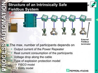
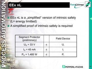
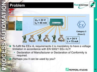
IS and Output Parameters
Repeaters
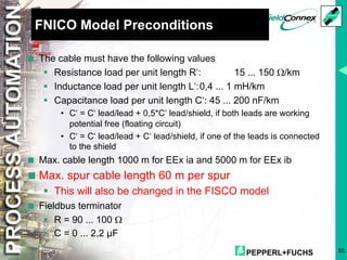
Concept U0 [V] I0 [mA] P0 [W] US [V] IS [mA] Cable Length[m] @
Entity 12,8 140 1.2 10.6 75 500
FISCO 15 207 1.93 12.6 110 750
non-I.S. -- -- -- 24 400 850
* @ IS, cable specification 18 AWG line type A, q=0,8mm2, 44W/km](https://image.slidesharecdn.com/connectingfieldbuspowerandknowledge-210319090802/85/Connecting-fieldbus-power-and-knowledge-25-320.jpg)
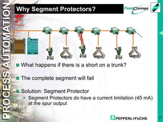


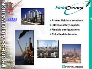
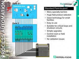
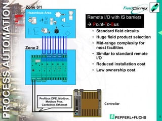
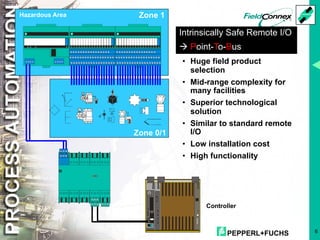
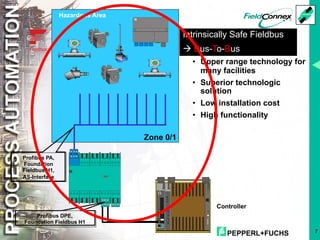
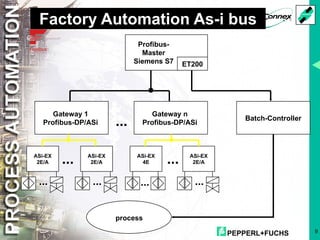
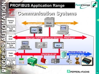
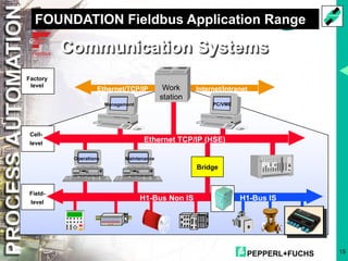
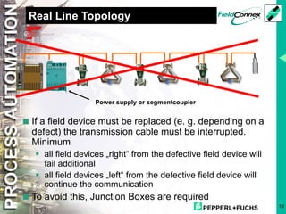
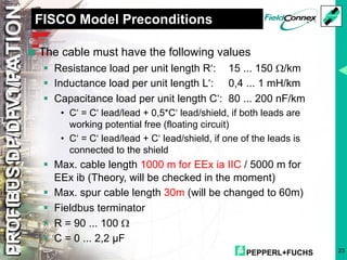
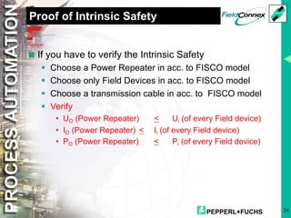
The document details the various fieldbus solutions and innovations provided by Pepperl+Fuchs, focusing on intrinsically safe systems for process automation. It discusses the advantages, configurations, and limitations of different types of fieldbus technologies, including FISCO and FNICO models, while highlighting their applications and considerations for hazardous environments. Additionally, it covers the architecture, topology, and necessary components like segment protectors and power repeaters to maintain efficient and safe communications in industrial settings.


