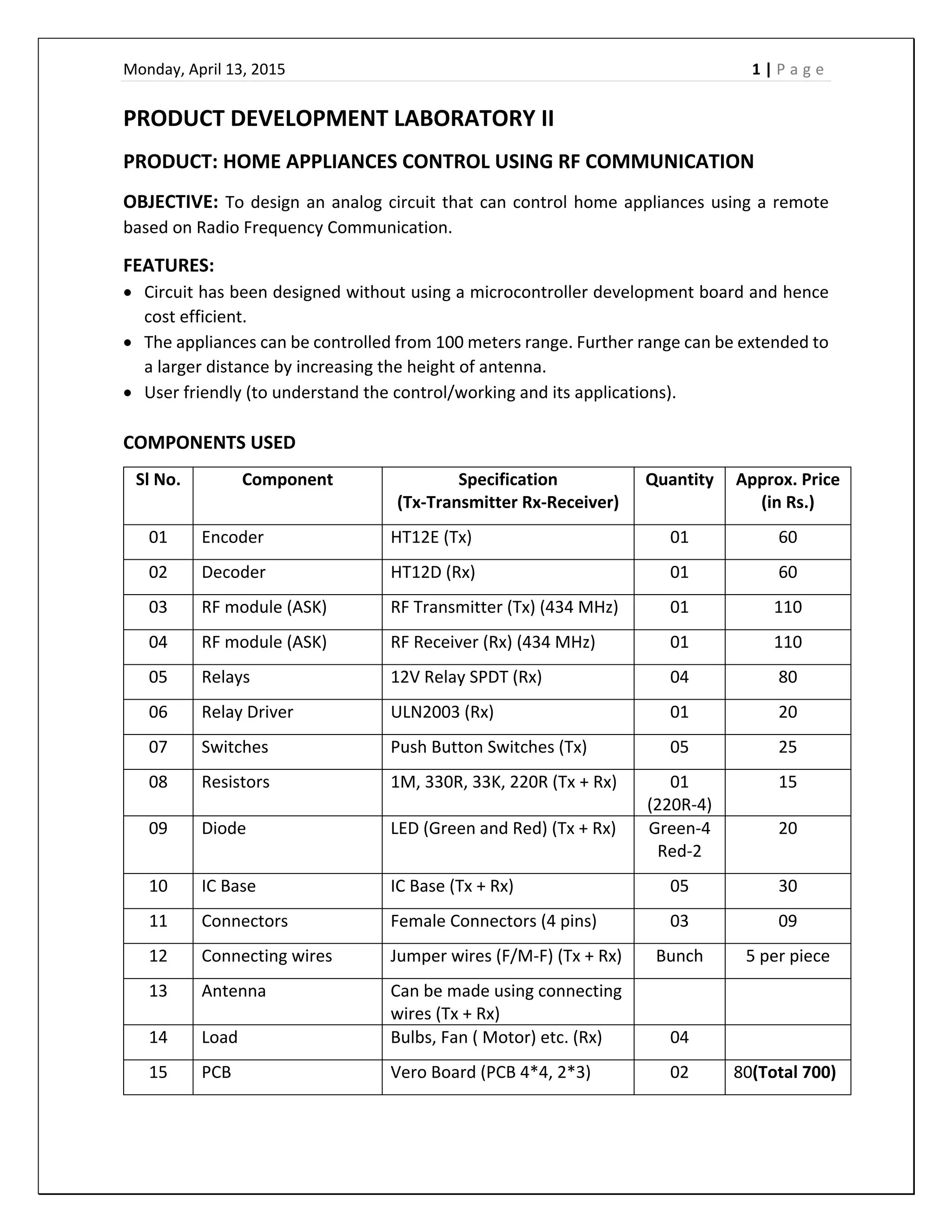
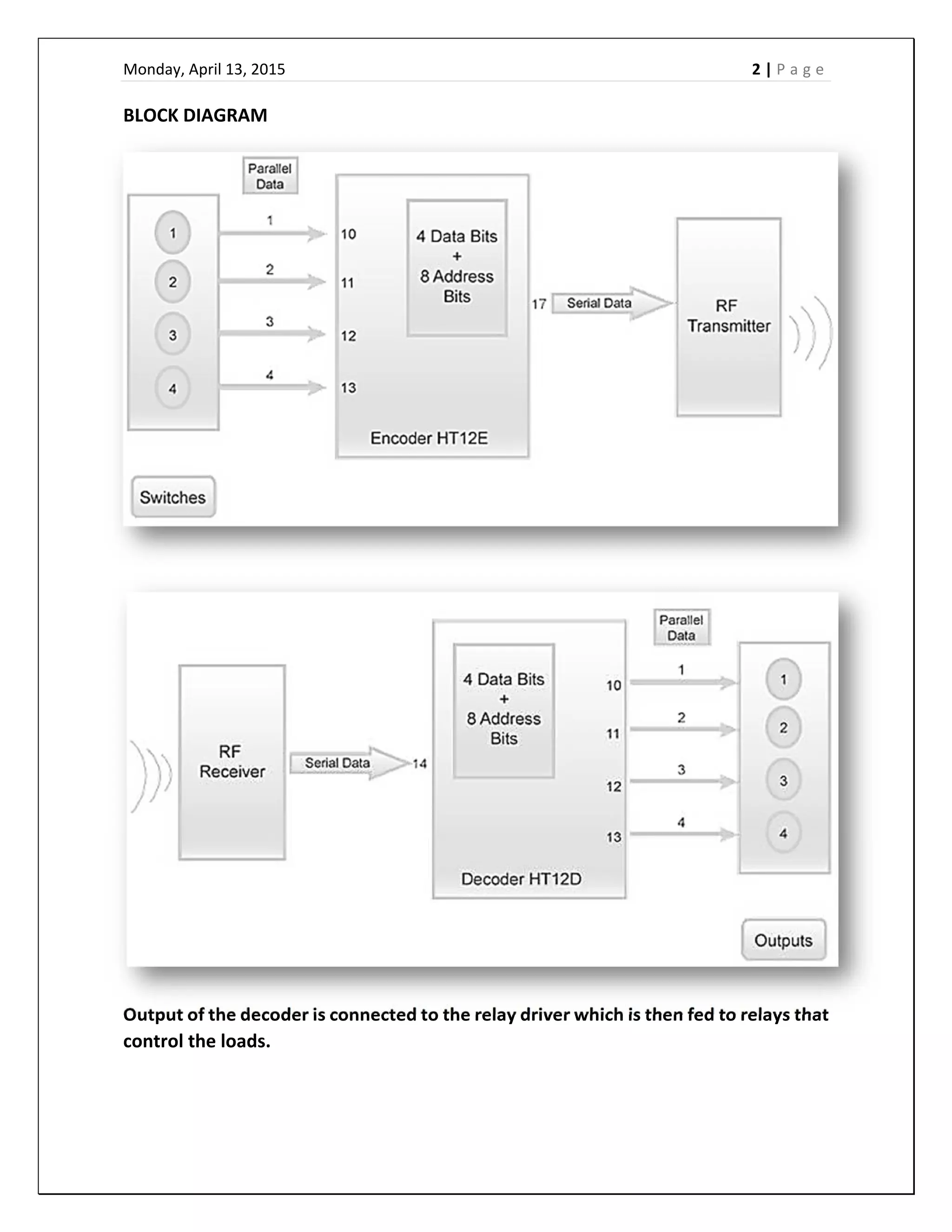
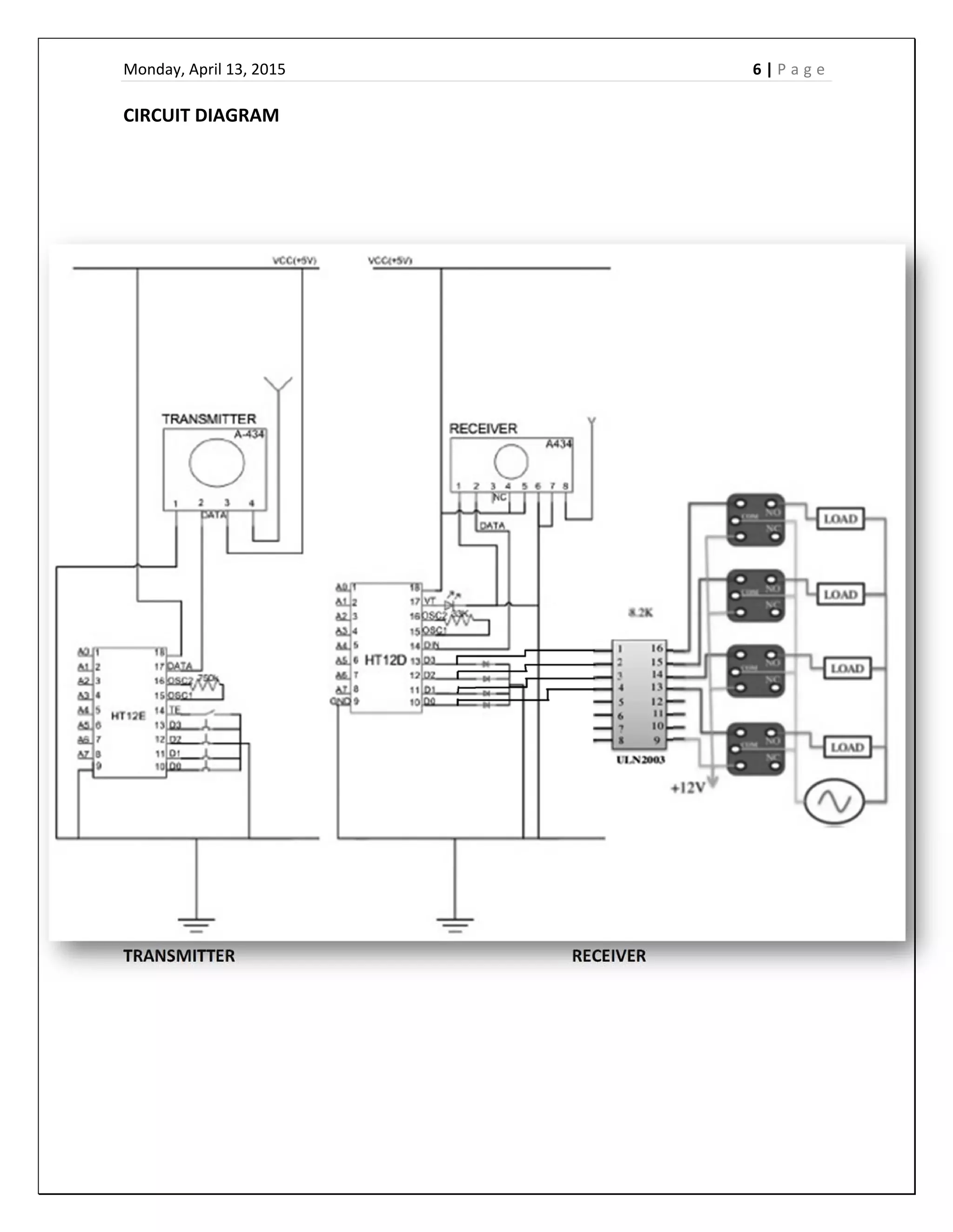
The document describes a circuit designed to control home appliances using radio frequency (RF) communication from a remote location. The circuit uses an RF transmitter and receiver operating at 434 MHz to transmit encoded signals from up to 100 meters away. An encoder converts parallel input signals to serial data for transmission, and a decoder at the receiver converts the signals back to parallel to control up to four relays and appliances. The circuit provides a low-cost way to wirelessly control appliances like lights and fans using RF signals.
automatic railway gate control system using arduinoantivirusspam
The objective of this project is to manage the control system of railway gate using the arduino. When train arrives at the sensing point alarm is triggered at the railway crossing point so that the people get intimation that gate is going to be closed. Then the control system activates and closes the gate on either side of the track once the train crosses the other end control system automatically lifts the gate.
This PPT is based on the communication between a PLC and a SCADA system. The numerous communication protocols such as Modbus, Profibus, ControlNET, DeviceNET, HART, Ethernet, and Profinet are briefly explained in this ppt.
This document contains the detailed construction ,working principle ,advantages disadvantages and applications of different sensors used in an mechatronic system.
Automatic Train Collision and Accidence Avoidance systemPradeepRaj
This is an idea presentation, which can be implemented in near future to drastically reduce the rate of train accidents.
It is based on the concept of Piezoelectric sensor, Ultrasonic sensor and Pattern recognition.
Data Acquisition System
Topics:Need of Data Acquisition System, DAQ Module, Sensors, Signal conditioning, DAQ hardware, DAQ software, DAQ processors, Advantages & Disadvantages.
Seminar Presentation on Programmeble Logic Controller , By an Engineering Student For doing Professional Presentation like Business Presentation, Industrial Use
Traffic density dependent taffic light controller pdf NAVODITA KUMARI
By using this system configuration we can reduce the possibilities of traffic jams caused by traffic lights to an extent. The number of passing vehicles on the road decides the density range of traffics and on the basis of vehicle count microcontroller decides the traffic light delays.
Data loggers are devices that record data over time.Data loggers have slower sample rates
Data loggers are implicitly stand-alone devices.Data loggers are extremely reliable.They are generally small, battery powered, portable, and equipped with a microprocessor,internal memory for data storage,and sensors.Data loggers can be deployed in a variety of environments to record measurements at set intervals for up to years at a time, unattended. Depending on the particular data logger, measurements can include air temperature, relative humidity, AC/DC current and voltage, differential pressure, time-of-use (lights, motors, etc.) ...
Introduction to DAS
Objectives of a DAS
Block diagram and explanation
Methodology
Hardware and software for DAS
Merits and Demerits of DAS/DQS
Conclusion
Automated irrigation system based on soil moisture using arduinoVishal Nagar
Automated irrigation system based on soil moisture using arduino
More Details: Contact me 9982228229
www.roofurja.com
vishalnagarcool.blogspot.com
https://www.youtube.com/watch?v=utHRD4B8BxQ
FOR FINDING THE RAILWAY TRACK FAULTS LIKE CRACK, INCLINATION, OBSTACLE. THE SYSTEM TRACK THE FAULT LOCATION AND SEND INFORMATION ABOUT FAULT TO THE AUTHORITY.
To develop a home automation system with a RF controlled remote. As technology is advancing so houses are also getting smarter. Modern houses are gradually shifting from conventional switches to centralized control system, involving RF controlled switches.
WIRELESS HOME AUTOMATION USING PIC MICROCONTROLLER BASED ON RF-MODULEEng.Manfred Kibona
This paper presents a project-based final year project course on completion of Bachelor degree in Telecommunication engineering. The goal of this project was to provide engineering students a hands-on experience involving actual engineering design on communication circuits, printed circuit board (PCB) design, layout, fabrication, assembly, and testing.
The scope of the project was been projected in develop a RF remote control system that will be capable for controlling various electrical appliances in the vicinity of 100 meters. The control signals has to traverse wirelessly by means of modulation with radio frequency carrier signal ranging from frequency band of 385MHz to 480MHz.
My Final Year Project - Individual Control Home Automation SystemMichael Olafusi
This project involves the design and construction of an individual control home
automation system using RS232, GSM technology and a microcontroller.
Home automation is the automatic or semi-automatic control and monitoring of
household appliances and residential house features like doors, gate and even the windows.
This project is a demonstration of how to design and build a multi purpose remotely
controlled system that can switch OFF and ON any electrical household appliance (including the security light), by dialling a phone already interfaced via RS232 to a microcontroller that controls a relay for the automatic switching on and off of the appliance and the phone will send a feedback short message service text indicating the new state of the appliance, whether switched ON or OFF.
The results of this project show that a microcontroller is a very powerful device for
building smart electronic devices that can automatically control electrical appliances, with little circuitry complexities and components.
This is to design a circuit such that one can control home or industrial appliance using the help of remote. This circuit can be used to any of your home appliances (lamp, fan, radio, etc.) to make the appliance turn on/off from a TV remote control.
Using remote to control appliances reduces human efforts without compromising on efficiency. It also saves time. Infrared (IR) light is an electromagnetic radiation with a wavelength longer than that of visible light, measured from the nominal edge of visible red light at 0.7 μm and extending conventionally to 300 μm,. These radiations with a frequency below our eyes sensitivity cannot be seen, but can only be felt by our skin temperature sensors. Infrared is interesting, because it is easily generated and doesn't suffer electromagnetic interference and so it is widely used in communication and control circuits. The adventure of using lots of infrared in TV remote controls helped engineers to work on innovative projects like controlling home appliances using TV remotes etc. Receiver in the circuit receives pulsed IR rays from the remote and decoded signal is thus received by relay driver whose output activates the corresponding home appliance. According to this, it makes sense that the logical direction about managing home appliances (HASs) in the near future is going to be by means of a remote control. But wireless technologies in domestics should be implemented carefully.
Each month, join us as we highlight and discuss hot topics ranging from the future of higher education to wearable technology, best productivity hacks and secrets to hiring top talent. Upload your SlideShares, and share your expertise with the world!
1w radio modem, 12V data module, wireless transmitter and wireless receiver, 2km control distance, RS232, RS485 convert to wireless. PTZ wireless control, AMR, LED Wireless display
10Gb/s Tunable SFP+ Transceiver Hot Pluggable, Duplex LC, +3.3V, 100GHz, Mono...Allen He
SHPP-10G-Tun tunable SFP+ Optical Transceiver provides a high-speed serial link at 9.95 to 11.3 Gbps data rates. It
complies with SFP+ Multi-Source Agreement (MSA) Specification. It provides Digital diagnostics functions via a 2-wire serial
interface as specified in SFF-8472. It fulfills the tunable via the monolithically Mach-Zehnder Modulators (MZM) laser. It support optical link up to 80km for SONET/SDH, 10G FC and Ethernet applications.
With advanced technology, people try to avail wireless technologies in different roles. In this paper, the RF modules are implemented as modernized wireless system to overcome the use of wire. RF transmitter and RF receiver are main devices of the system. And then LED, transformer, relay, and push buttons are used as supporting components of the system. HT12E and HT12D are mainly used for decoding and encoding the data. The HT12E encoder IC converts the 4 bit data from the 4 data pins that are connected to buttons into serial data. This serial data is sent to RF transmitter. The RF transmitter transmits this serial data using signals. At the receiver side, the RF receiver receives the serial data. This serial data is sent to HT12D decoder IC which converts into 4 bit parallel data. The 4 data pins of decoder are connected to LEDs. According to the button pushed, the LEDs can be turned ON and OFF meaning that the specific task or function can be carried out by mean of remote predefined key. In today's world, there is a continuous need for wireless control using with transmitter and receiver in standard and modern living. Dr. Thida Aung "Wireless Remote using RF Module" Published in International Journal of Trend in Scientific Research and Development (ijtsrd), ISSN: 2456-6470, Volume-3 | Issue-5 , August 2019, URL: https://www.ijtsrd.com/papers/ijtsrd26780.pdf Paper URL: https://www.ijtsrd.com/engineering/electronics-and-communication-engineering/26780/wireless-remote-using-rf-module/dr-thida-aung
One of the greatest challenges engineers face is the safe operation of the existing civil infrastructure. Tunnels progressively deteriorate due to ageing ,environmental factors ,increased loading ,damages caused by the human/natural factors ,inadequate poor maintenance
How to Make a Field invisible in Odoo 17Celine George
It is possible to hide or invisible some fields in odoo. Commonly using “invisible” attribute in the field definition to invisible the fields. This slide will show how to make a field invisible in odoo 17.
We all have good and bad thoughts from time to time and situation to situation. We are bombarded daily with spiraling thoughts(both negative and positive) creating all-consuming feel , making us difficult to manage with associated suffering. Good thoughts are like our Mob Signal (Positive thought) amidst noise(negative thought) in the atmosphere. Negative thoughts like noise outweigh positive thoughts. These thoughts often create unwanted confusion, trouble, stress and frustration in our mind as well as chaos in our physical world. Negative thoughts are also known as “distorted thinking”.
Ethnobotany and Ethnopharmacology:
Ethnobotany in herbal drug evaluation,
Impact of Ethnobotany in traditional medicine,
New development in herbals,
Bio-prospecting tools for drug discovery,
Role of Ethnopharmacology in drug evaluation,
Reverse Pharmacology.
The French Revolution, which began in 1789, was a period of radical social and political upheaval in France. It marked the decline of absolute monarchies, the rise of secular and democratic republics, and the eventual rise of Napoleon Bonaparte. This revolutionary period is crucial in understanding the transition from feudalism to modernity in Europe.
For more information, visit-www.vavaclasses.com
How to Create Map Views in the Odoo 17 ERPCeline George
The map views are useful for providing a geographical representation of data. They allow users to visualize and analyze the data in a more intuitive manner.
2024.06.01 Introducing a competency framework for languag learning materials ...Sandy Millin
http://sandymillin.wordpress.com/iateflwebinar2024
Published classroom materials form the basis of syllabuses, drive teacher professional development, and have a potentially huge influence on learners, teachers and education systems. All teachers also create their own materials, whether a few sentences on a blackboard, a highly-structured fully-realised online course, or anything in between. Despite this, the knowledge and skills needed to create effective language learning materials are rarely part of teacher training, and are mostly learnt by trial and error.
Knowledge and skills frameworks, generally called competency frameworks, for ELT teachers, trainers and managers have existed for a few years now. However, until I created one for my MA dissertation, there wasn’t one drawing together what we need to know and do to be able to effectively produce language learning materials.
This webinar will introduce you to my framework, highlighting the key competencies I identified from my research. It will also show how anybody involved in language teaching (any language, not just English!), teacher training, managing schools or developing language learning materials can benefit from using the framework.
How to Split Bills in the Odoo 17 POS ModuleCeline George
Bills have a main role in point of sale procedure. It will help to track sales, handling payments and giving receipts to customers. Bill splitting also has an important role in POS. For example, If some friends come together for dinner and if they want to divide the bill then it is possible by POS bill splitting. This slide will show how to split bills in odoo 17 POS.
The Roman Empire A Historical Colossus.pdfkaushalkr1407
The Roman Empire, a vast and enduring power, stands as one of history's most remarkable civilizations, leaving an indelible imprint on the world. It emerged from the Roman Republic, transitioning into an imperial powerhouse under the leadership of Augustus Caesar in 27 BCE. This transformation marked the beginning of an era defined by unprecedented territorial expansion, architectural marvels, and profound cultural influence.
The empire's roots lie in the city of Rome, founded, according to legend, by Romulus in 753 BCE. Over centuries, Rome evolved from a small settlement to a formidable republic, characterized by a complex political system with elected officials and checks on power. However, internal strife, class conflicts, and military ambitions paved the way for the end of the Republic. Julius Caesar’s dictatorship and subsequent assassination in 44 BCE created a power vacuum, leading to a civil war. Octavian, later Augustus, emerged victorious, heralding the Roman Empire’s birth.
Under Augustus, the empire experienced the Pax Romana, a 200-year period of relative peace and stability. Augustus reformed the military, established efficient administrative systems, and initiated grand construction projects. The empire's borders expanded, encompassing territories from Britain to Egypt and from Spain to the Euphrates. Roman legions, renowned for their discipline and engineering prowess, secured and maintained these vast territories, building roads, fortifications, and cities that facilitated control and integration.
The Roman Empire’s society was hierarchical, with a rigid class system. At the top were the patricians, wealthy elites who held significant political power. Below them were the plebeians, free citizens with limited political influence, and the vast numbers of slaves who formed the backbone of the economy. The family unit was central, governed by the paterfamilias, the male head who held absolute authority.
Culturally, the Romans were eclectic, absorbing and adapting elements from the civilizations they encountered, particularly the Greeks. Roman art, literature, and philosophy reflected this synthesis, creating a rich cultural tapestry. Latin, the Roman language, became the lingua franca of the Western world, influencing numerous modern languages.
Roman architecture and engineering achievements were monumental. They perfected the arch, vault, and dome, constructing enduring structures like the Colosseum, Pantheon, and aqueducts. These engineering marvels not only showcased Roman ingenuity but also served practical purposes, from public entertainment to water supply.
Model Attribute Check Company Auto PropertyCeline George
In Odoo, the multi-company feature allows you to manage multiple companies within a single Odoo database instance. Each company can have its own configurations while still sharing common resources such as products, customers, and suppliers.
Palestine last event orientationfvgnh .pptxRaedMohamed3
An EFL lesson about the current events in Palestine. It is intended to be for intermediate students who wish to increase their listening skills through a short lesson in power point.
How libraries can support authors with open access requirements for UKRI fund...
Home appliances control using RF communication
1. Monday, April 13, 2015 1 | P a g e
PRODUCT DEVELOPMENT LABORATORY II
PRODUCT: HOME APPLIANCES CONTROL USING RF COMMUNICATION
OBJECTIVE: To design an analog circuit that can control home appliances using a remote
based on Radio Frequency Communication.
FEATURES:
Circuit has been designed without using a microcontroller development board and hence
cost efficient.
The appliances can be controlled from 100 meters range. Further range can be extended to
a larger distance by increasing the height of antenna.
User friendly (to understand the control/working and its applications).
COMPONENTS USED
Sl No. Component Specification
(Tx‐Transmitter Rx‐Receiver)
Quantity Approx. Price
(in Rs.)
01 Encoder HT12E (Tx) 01 60
02 Decoder HT12D (Rx) 01 60
03 RF module (ASK) RF Transmitter (Tx) (434 MHz) 01 110
04 RF module (ASK) RF Receiver (Rx) (434 MHz) 01 110
05 Relays 12V Relay SPDT (Rx) 04 80
06 Relay Driver ULN2003 (Rx) 01 20
07 Switches Push Button Switches (Tx) 05 25
08 Resistors 1M, 330R, 33K, 220R (Tx + Rx) 01
(220R‐4)
15
09 Diode LED (Green and Red) (Tx + Rx) Green‐4
Red‐2
20
10 IC Base IC Base (Tx + Rx) 05 30
11 Connectors Female Connectors (4 pins) 03 09
12 Connecting wires Jumper wires (F/M‐F) (Tx + Rx) Bunch 5 per piece
13 Antenna Can be made using connecting
wires (Tx + Rx)
14 Load Bulbs, Fan ( Motor) etc. (Rx) 04
15 PCB Vero Board (PCB 4*4, 2*3) 02 80(Total 700)
2. Monday, April 13, 2015 2 | P a g e
BLOCK DIAGRAM
Output of the decoder is connected to the relay driver which is then fed to relays that
control the loads.
3. Monday, April 13, 2015 3 | P a g e
COMPONENTS DESCRIPTION
HT12E
The 212
encoders are a series of CMOS LSIs for remote control system
applications. They are capable of encoding information which consists of
N address bits and 12‐N data bits. Each address/data input can be set to
one of the two logic states. The programmed addresses/data are
transmitted together with the header bits via an RF or an infrared
transmission medium upon receipt of a trigger signal. The capability to
select a TE trigger on the HT12E further enhances the application
flexibility of the 212
series of encoders.
Features
‐ Operating voltage ‐ 2.4V‐12V for the HT12E.
‐ Low power and high noise immunity CMOS technology.
‐ Low standby current: 0.1 uA (typ.) at VDD = 5V.
‐ Four words transmission for the HT12E.
‐ Built‐in oscillator needs only 5% resistor.
‐ Data code has positive polarity.
‐ Minimal external components.
‐ Pair with Holtek’s 212
series of decoders.
‐ 18‐pin DIP, 20‐pin SOP package.
HT12D
The 212
decoders are a series of CMOS LSIs for remote control system
applications. They are paired with Holtek’s 212
series of encoders (refer to
the encoder/decoder cross reference table). For proper operation, a pair
of encoder/decoder with the same number of addresses and data format
should be chosen. The decoders receive serial addresses and data from a
programmed 212
series of encoders that are transmitted by a carrier using
an RF or an IR transmission medium. They compare the serial input data
three times continuously with their local addresses. If no error or
unmatched codes are found, the input data codes are decoded and then
transferred to the output pins. The VT pin also goes high to indicate a valid
transmission. The 212
series of decoders are capable of decoding
informations that consist of N bits of address and 12‐N bits of data. Of this
series, the HT12D is arranged to provide 8 address bits and 4 data bits.
Features
‐ Operating voltage: 2.4V~12V.
‐ Low power and high noise immunity CMOS technology.
‐ Low standby current.
‐ Capable of decoding 12 bits of information.
‐ Binary address setting.
4. Monday, April 13, 2015 4 | P a g e
‐ Received codes are checked 3 times.
‐ Address/Data number combination.
‐ HT12D: 8 address bits and 4 data bits.
‐ Built‐in oscillator needs only 5% resistor.
‐ Valid transmission indicator.
‐ Easy interface with an RF or an infrared transmission medium.
‐ Minimal external components.
‐ Pair with Holtek’s 212
series of encoders.
‐ 18‐pin DIP, 20‐pin SOP package.
RF ASK Module (434 MHz)
The RF module, as the name suggests, operates at Radio Frequency. The
corresponding frequency range varies between 30 kHz & 300 GHz. In this
RF system, the digital data is represented as variations in the amplitude
of carrier wave. This kind of modulation is known as Amplitude Shift
Keying (ASK).
Why RF is preferred over IR?
Transmission through RF is better than IR (infrared) because of many
reasons.
‐ Firstly, signals through RF can travel through larger distances making
it suitable for long range applications.
‐ Also, while IR mostly operates in line‐of‐sight mode, RF signals can
travel even when there is an obstruction between transmitter &
receiver.
‐ Next, RF transmission is more strong and reliable than IR
transmission.
‐ RF communication uses a specific frequency unlike IR signals which
are affected by other IR emitting sources.
This RF module comprises of an RF Transmitter and an RF Receiver. The
transmitter/receiver (Tx/Rx) pair operates at a frequency of 434 MHz. An
RF transmitter receives serial data and transmits it wirelessly through RF
through its antenna connected at pin4. The transmission occurs at the
rate of 1Kbps ‐ 10Kbps.The transmitted data is received by an RF receiver
operating at the same frequency as that of the transmitter.
The RF module is often used along with a pair of encoder/decoder. The
encoder is used for encoding parallel data for transmission feed while
reception is decoded by a decoder. HT12E‐HT12D, HT640‐HT648, etc. are
some commonly used encoder/decoder pair ICs.
5. Monday, April 13, 2015 5 | P a g e
RELAY
A relay is an electrically operated switch. Many relays use
an electromagnet to mechanically operate a switch, but other operating
principles are also used, such as solid‐state relays. Relays are used where
it is necessary to control a circuit by a low‐power signal (with complete
electrical isolation between control and controlled circuits), or where
several circuits must be controlled by one signal. A relay switches one or
more poles, each of whose contacts can be thrown by energizing the coil.
Normally‐open (NO) contacts connect the circuit when the relay is
activated; the circuit is disconnected when the relay is inactive. It is also
called a "Form A" contact or "make" contact. NO contacts may also be
distinguished as "early‐make" or "NOEM", which means that the contacts
close before the button or switch is fully engaged. Normally‐closed (NC)
contacts disconnect the circuit when the relay is activated; the circuit is
connected when the relay is inactive. It is also called a "Form B" contact
or "break" contact. NC contacts may also be distinguished as "late‐break"
or "NCLB", which means that the contacts stay closed until the button or
switch is fully disengaged. SPDT ‐ Single Pole Double Throw, a common
terminal connects to either of two others. Including two for the coil, such
a relay has five terminals in total.
RELAY DRIVER ULN2003A
The ULN2003A is a high‐voltage, high‐current Darlington transistor array. It
consists of seven NPN Darlington pairs that feature high‐voltage outputs with
common‐cathode fly back diodes for switching inductive loads. The drivers can
be paralleled for higher current capability, even stacking one chip on top of
another, both electrically and physically has been done. Generally it can also be
used for interfacing with stepper motor, where the motor requires high ratings
which cannot be provided by other interfacing devices.
Features
500 mA rated collector current (single output)
50 V output
Includes output fly back diodes
Inputs compatible with various types of logic
Typical usage of the ULN2003A is to drive relays, lamp and LED
displays or stepper motors Logic buffers, Line drivers, Hammer driver.
7. Monday, April 13, 2015 7 | P a g e
WORKING
This circuit utilizes the RF module (Tx/Rx) for making a wireless remote, which could be used
to drive an output from a distant place. RF module, as the name suggests, uses radio frequency
to send signals. These signals are transmitted at a particular frequency and a baud rate. A
receiver can receive these signals only if it is configured for that frequency. A four channel
encoder/decoder pair has also been used in this system. The input signals, at the transmitter
side, are taken through four switches while the outputs are monitored on a set of four LEDs
corresponding to each input switch. The circuit can be used for designing Remote Appliance
Control system. The outputs from the receiver can drive corresponding relays connected to
any household appliance.
This radio frequency (RF) transmission system employs Amplitude Shift Keying (ASK) with
transmitter/receiver (Tx/Rx) pair operating at 434 MHz. The transmitter module takes serial
input and transmits these signals through RF. The transmitted signals are received by the
receiver module placed away from the source of transmission. The system allows one way
communication between two nodes, namely, transmission and reception. The RF module has
been used in conjunction with a set of four channel encoder/decoder ICs. Here HT12E &
HT12D have been used as encoder and decoder respectively. The encoder converts the
parallel inputs (from the remote switches) into serial set of signals. These signals are serially
transferred through RF to the reception point. The decoder is used after the RF receiver to
decode the serial format and retrieve the original signals as outputs. These outputs can be
observed on corresponding LEDs.
Encoder IC (HT12E) receives parallel data in the form of address bits and control bits. The
control signals from remote switches along with 8 address bits constitute a set of 12 parallel
signals. The encoder HT12E encodes these parallel signals into serial bits. Transmission is
enabled by providing ground to pin14 which is active low. The control signals are given at pins
10‐13 of HT12E. The serial data is fed to the RF transmitter through pin17 of HT12E.
Transmitter, upon receiving serial data from encoder IC (HT12E), transmits it wirelessly to the
RF receiver. The receiver, upon receiving these signals, sends them to the decoder IC (HT12D)
through pin2. The serial data is received at the data pin (DIN, pin14) of HT12D. The decoder
then retrieves the original parallel format from the received serial data.
When no signal is received at data pin of HT12D, it remains in standby mode and consumes
very less current (less than 1μA) for a voltage of 5V. When signal is received by receiver, it is
given to DIN pin (pin14) of HT12D. On reception of signal, oscillator of HT12D gets activated.
IC HT12D then decodes the serial data and checks the address bits three times. If these bits
match with the local address pins (pins 1‐8) of HT12D, then it puts the data bits on its data
pins (pins 10‐13) and makes the VT pin high. An LED is connected to VT pin (pin17) of the
decoder. This LED works as an indicator to indicate a valid transmission. The corresponding
output is thus generated at the data pins of decoder IC. A signal is sent by lowering any or all
8. Monday, April 13, 2015 8 | P a g e
the pins 10‐13 of HT12E and corresponding signal is received at receiver’s end (at HT12D).
Address bits are configured by using the by using the first 8 pins of both encoder and decoder
ICs. To send a particular signal, address bits must be same at encoder and decoder ICs. By
configuring the address bits properly, a single RF transmitter can also be used to control
different RF receivers of same frequency.
To summarize, on each transmission, 12 bits of data is transmitted consisting of 8 address bits
and 4 data bits. The signal is received at receiver’s end which is then fed into decoder IC. If
address bits get matched, decoder converts it into parallel data and the corresponding data
bits get lowered which could be then used to drive the LEDs.
Amplitude Shift Keying (ASK)
It is a form of amplitude modulation that represents digital data as variations in
the amplitude of a carrier wave. In an ASK system, the binary symbol 1 is represented by
transmitting a fixed‐amplitude carrier wave and fixed frequency for a bit duration of T seconds.
If the signal value is 1 then the carrier signal will be transmitted; otherwise, a signal value of 0
will be transmitted.
Antenna Specification
‐ The recommended length of the antenna is 17cm.
‐ Coiling the antenna up will shorten the range.
‐ For best reception mount it vertical and on a suitable ground plane, (a conducting surface)
as high as one can manage.
IMPLEMENTATION AND TESTING
The circuit is simulated using NI Multisim and the transmitter and receiver circuits were
tested on breadboard. The final circuit was implemented on Vero‐board by manual
Soldering. After soldering the components on to the PCB, the boards were thoroughly cleaned
for removing any residual flux and wire leads. All the components are checked for their values
and proper orientation if applicable. Before ICs were inserted into the sockets, power was
applied to the board and voltages were measured at the IC power points. Other DC voltages
were also checked if possible. Then power was removed from the board, and ICs were inserted
into the sockets, checking the proper orientation. Power was again applied to the board
expected voltages and signals were monitored. The supply voltages were monitored and
verified. Working was tested and the product was completed.
9. Monday, April 13, 2015 9 | P a g e
APPLICATIONS
Radio remote control is used to control distance objects using a variety of radio signals
transmitted by the remote control device. As a complementary method to infrared remote
controls, the radio remote control is used with electric garage door or gate openers,
automatic barrier systems, burglar alarms and industrial automation systems.
Home appliances control and industrial applications
RF is used in jamming circuit for military purposes.
A remote controlled device primarily saves a lot of time and energy. Its significance in
today’s world is immense when people don’t have to unnecessarily waste their time in
operating the appliances by being near to the appliance. They can operate it while they’re
engrossed in whatever task they’re doing and don’t have to bother leaving it in between.
The remote control can extend up to a long distance depending on the frequency used
and the efficiency of the circuit. It is an advantage that it can be operated from distances.
Tediousness of operating the appliance in its close proximity is done away with. The circuit
has the advantages that it can be easily implemented using easily available and low cost
components. The maintenance is also easy.
Advantages
‐ Highly Sensitive
‐ Very low noise
‐ Low cost and reliable circuit
‐ The appliances can be controlled from 100 meters range. Further range can be extended
to a larger distance by increasing the height of antenna.
‐ Can handle heavy loads up to 7 Amperes.
CONCLUSION
The product to demonstrate the remote controlled operation of multiple home appliances is
designed.
10. Monday, April 13, 2015 10 | P a g e
REFERENCES
1. http://arif‐ece.blogspot.com/2010/05/tv‐remote‐controlled‐home‐appliance.html
2. http://arif‐ece.blogspot.com/2010_05_01_archive.html
3. http://www.circuitstoday.com/category/remote‐circuits
4. http://www.satsleuth.com/schematics.htm
5. http://www.printsasia.com/book/Electronic‐Projects‐for‐Beginners‐Using‐Easily‐
AvailableElectronic‐Components‐with‐A‐Primer‐on‐Basic‐8122301525‐9788122301526
6. http://www.dapj.net/hobby/?paged=2
7. http://extremeelectronics.co.in/