Download to read offline

![250 mm
250 mm
250 mm
- 7 -
DS
Product line
OD
EC/R
Outputs
0 - Analog: Sine/Cosine
C - Digital : AqB + index (external module SC2AqB)
D - Digital : SSi (external module SC2SSi03)
Binary
ResoluƟ on
CPR
32,768
16,384
4,096
8,192
65,536
Toll Free Phone (877) SERVO98
Toll Free Fax (877) SERV099
131,072
ELECTROMATE
www.electromate.com
sales@electromate.com
524,288
Bit 12 13 14 15 16 17 18 19 20
Code A B C D E F G H I
DS - 247- 128 - DI - C
Connector
Decimal
ResoluƟ on
CPR
64,000
128,000
32,000
16,000
8,000
512,000
Bit 13 14 15 16 17 18 19 20
Code K L M N O P Q R
Ordering
262,144
256,000
SC2SSi external module
CAT # SC2SSi-03 [42 x 13 mm] Default
CAT # SC2SSi-05 [30 x 13 mm]
AWG32 Teflon isolated
250 mm
AWG32 Teflon isolated
AWG32 Teflon isolated
SC2AqB external module
CAT # SC2AqB-00 [25 x 20 mm]
AWG32 Teflon isolated
250 mm
AWG32 Teflon isolated
Analog Sin/Cosine
Digital SSi
Digital AqB
1,048,576
1,0124,000
Sold & Serviced By:](https://image.slidesharecdn.com/netzerds-247-128specsheet-141018122438-conversion-gate01/85/Netzer-ds-247-128-specsheet-7-320.jpg)

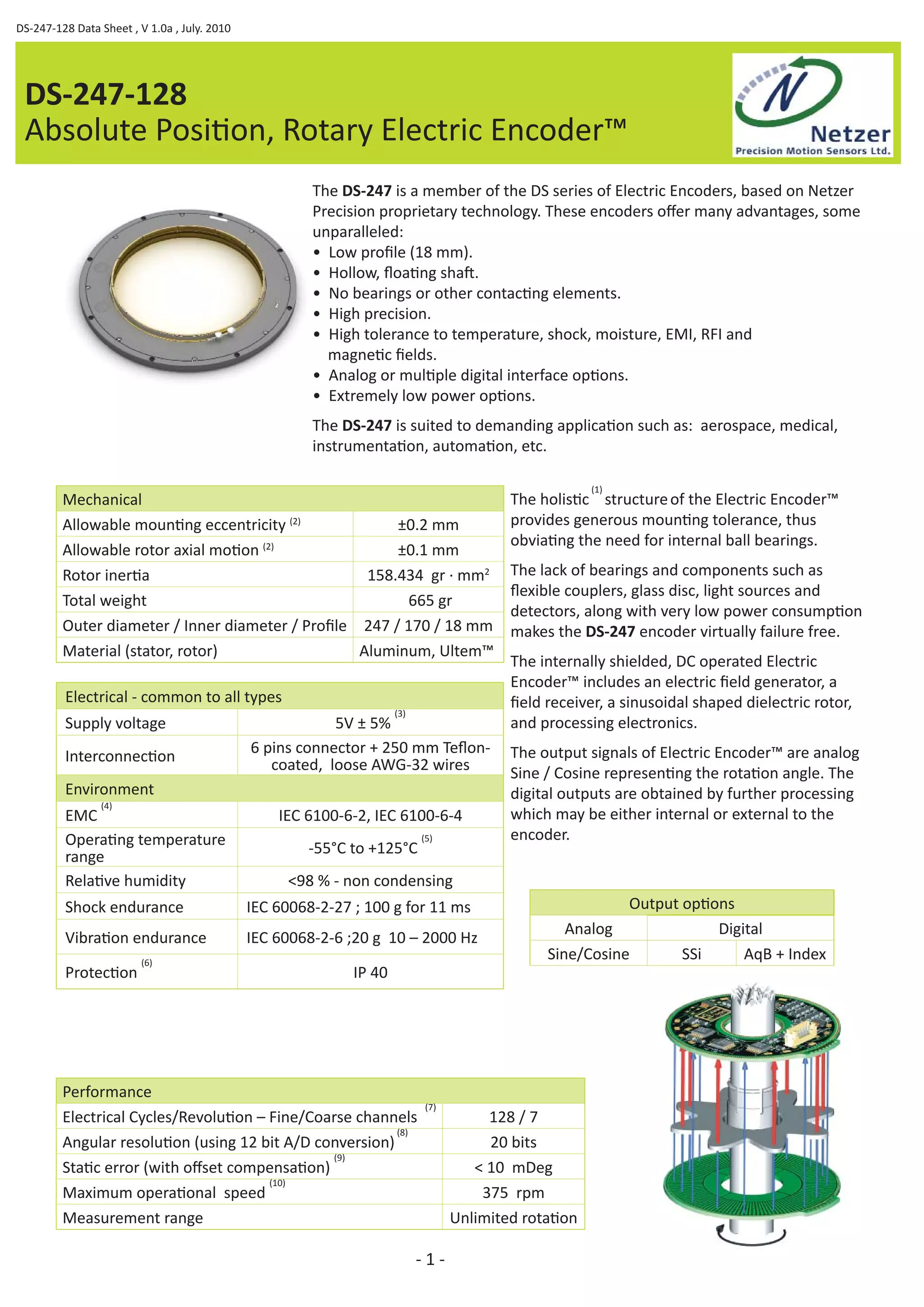
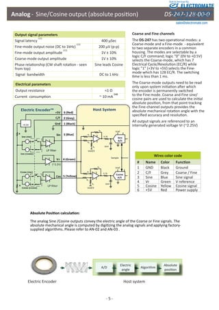
The document is a data sheet for the DS-247-128 absolute position rotary electric encoder. It provides specifications for the encoder including its low profile design, hollow shaft, high precision and tolerance to environmental factors. It outputs either analog sine/cosine waves or digital quadrature signals and has options for various interfaces like SSi or A/B/Index. It is suited for applications requiring high accuracy like aerospace and medical equipment.


![Getting Started with Apache Spark: Big Data Made Simple [Free Meetup]](https://cdn.slidesharecdn.com/ss_thumbnails/apachesparkgettingstarted-260203175547-8361bcc3-thumbnail.jpg?width=640&height=640&fit=bounds)


