This document summarizes a student's study of the boiler system at the NTPC Ramagundam thermal power station in India. Key points:
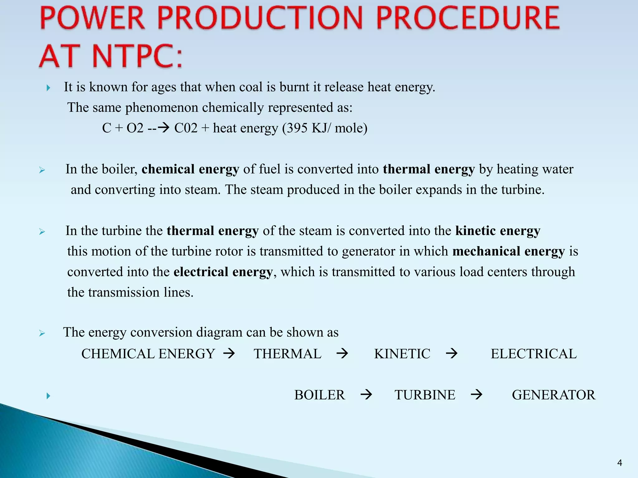
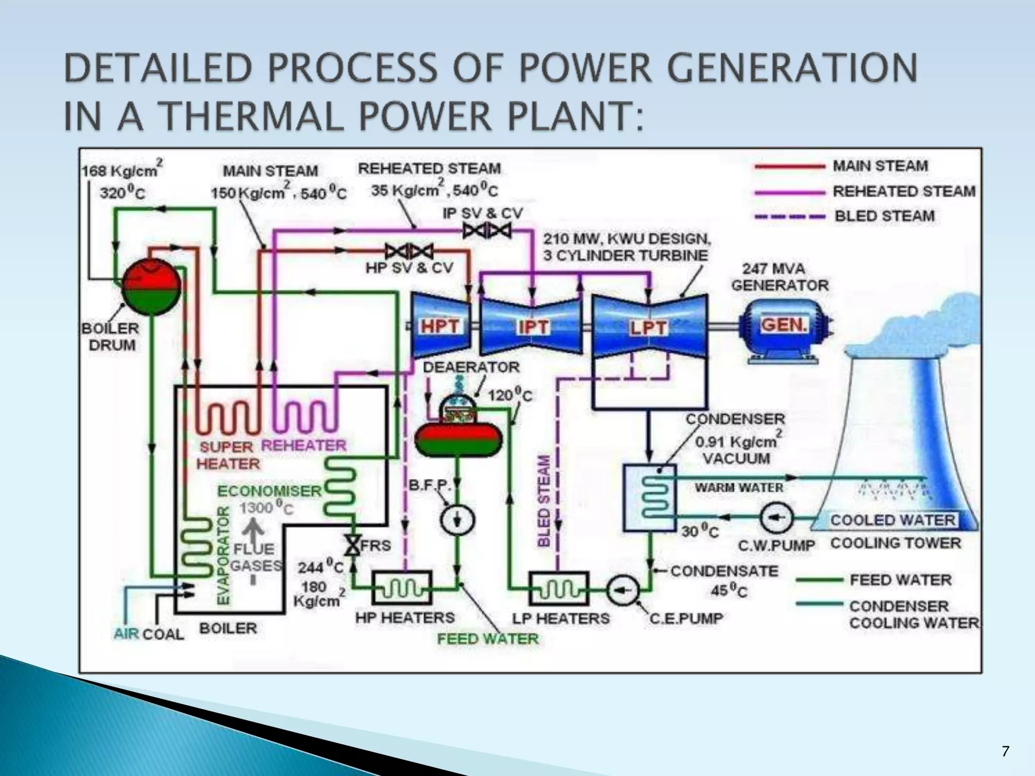
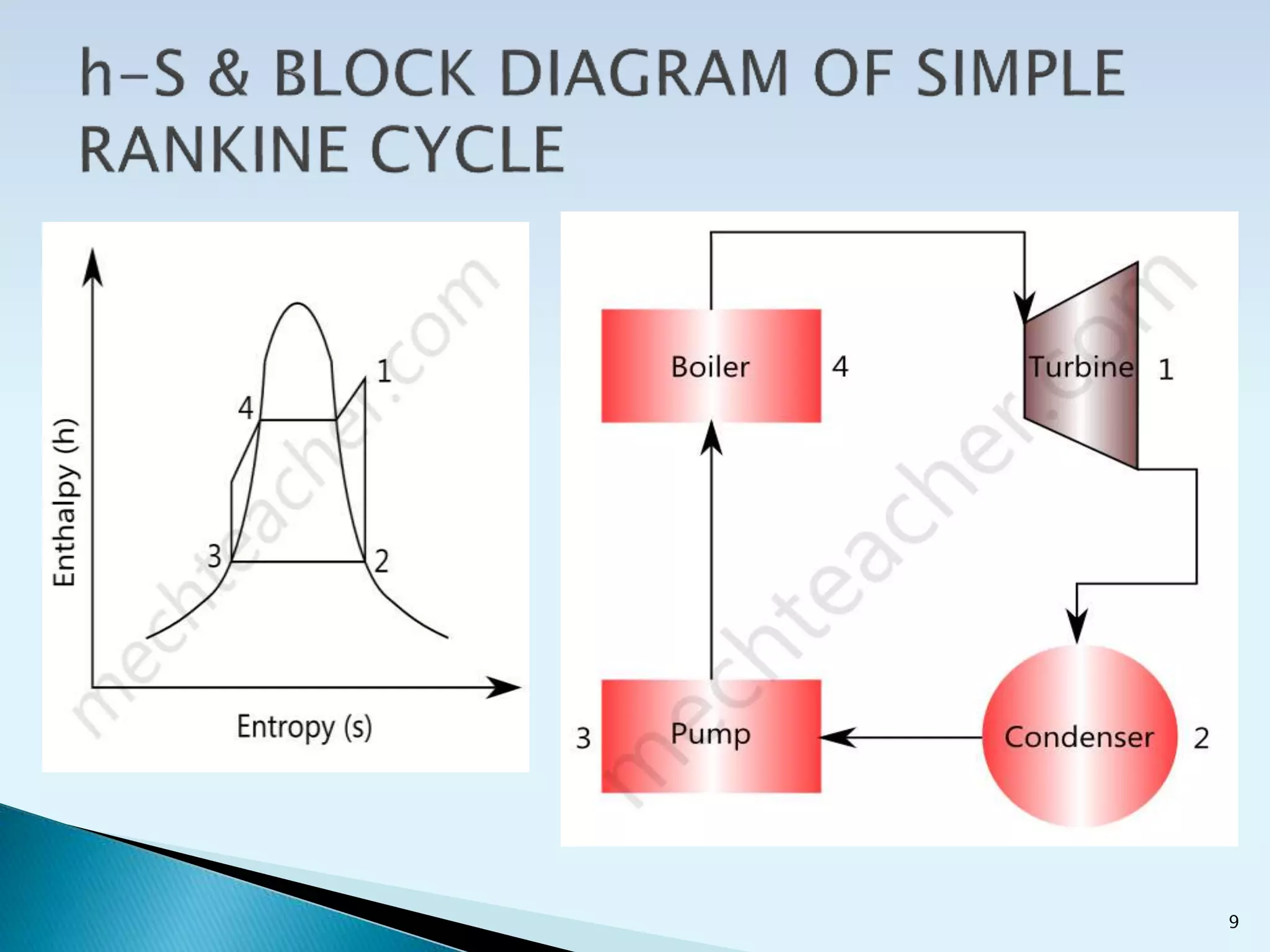
- The study examines how coal is combusted in the boiler to generate high-pressure steam, which is then used to power turbines and generate electricity.
- The NTPC plant uses high-pressure water tube boilers fueled by pulverized coal. It can generate 2600MW of power through 7 generating units.
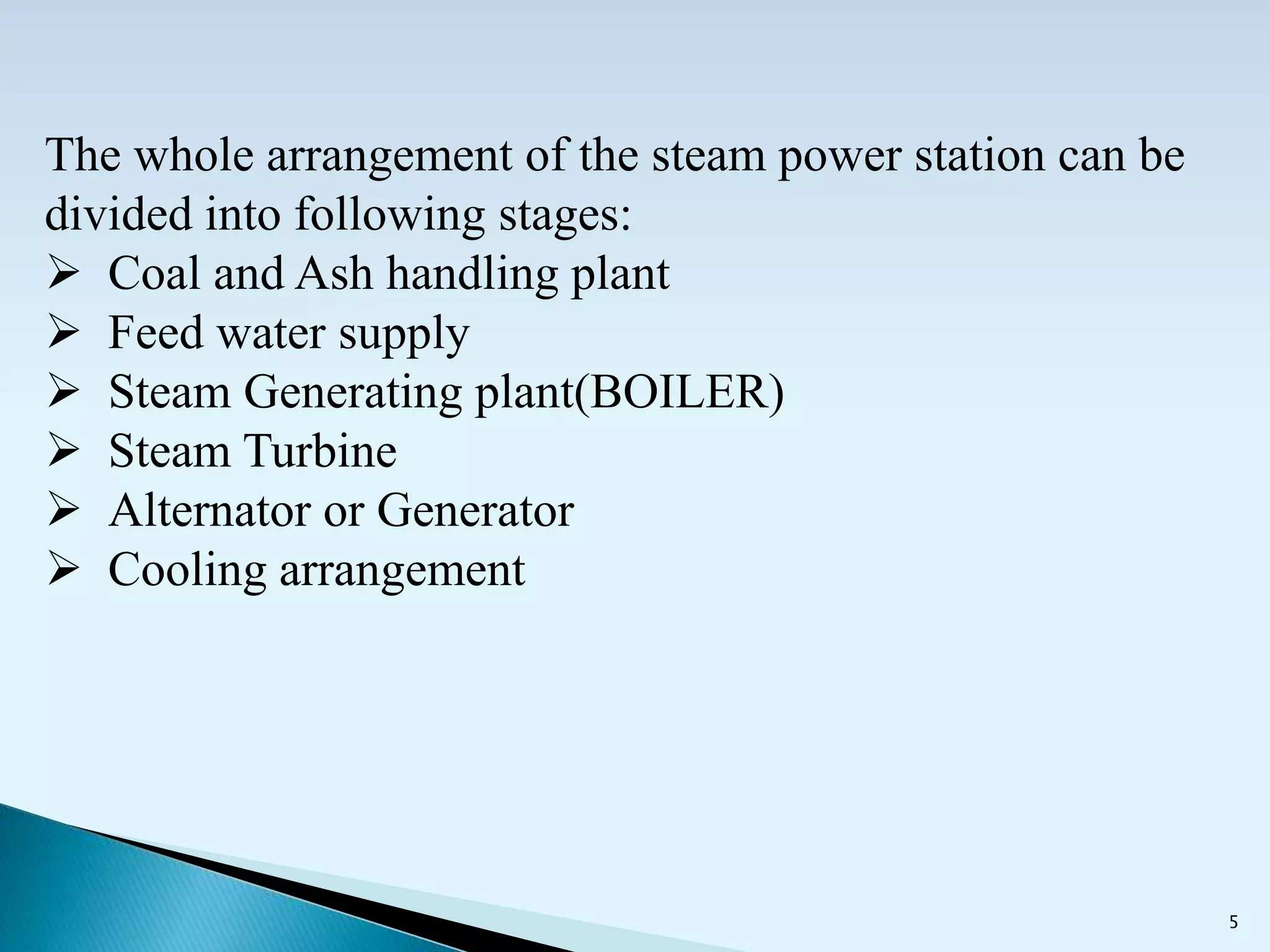
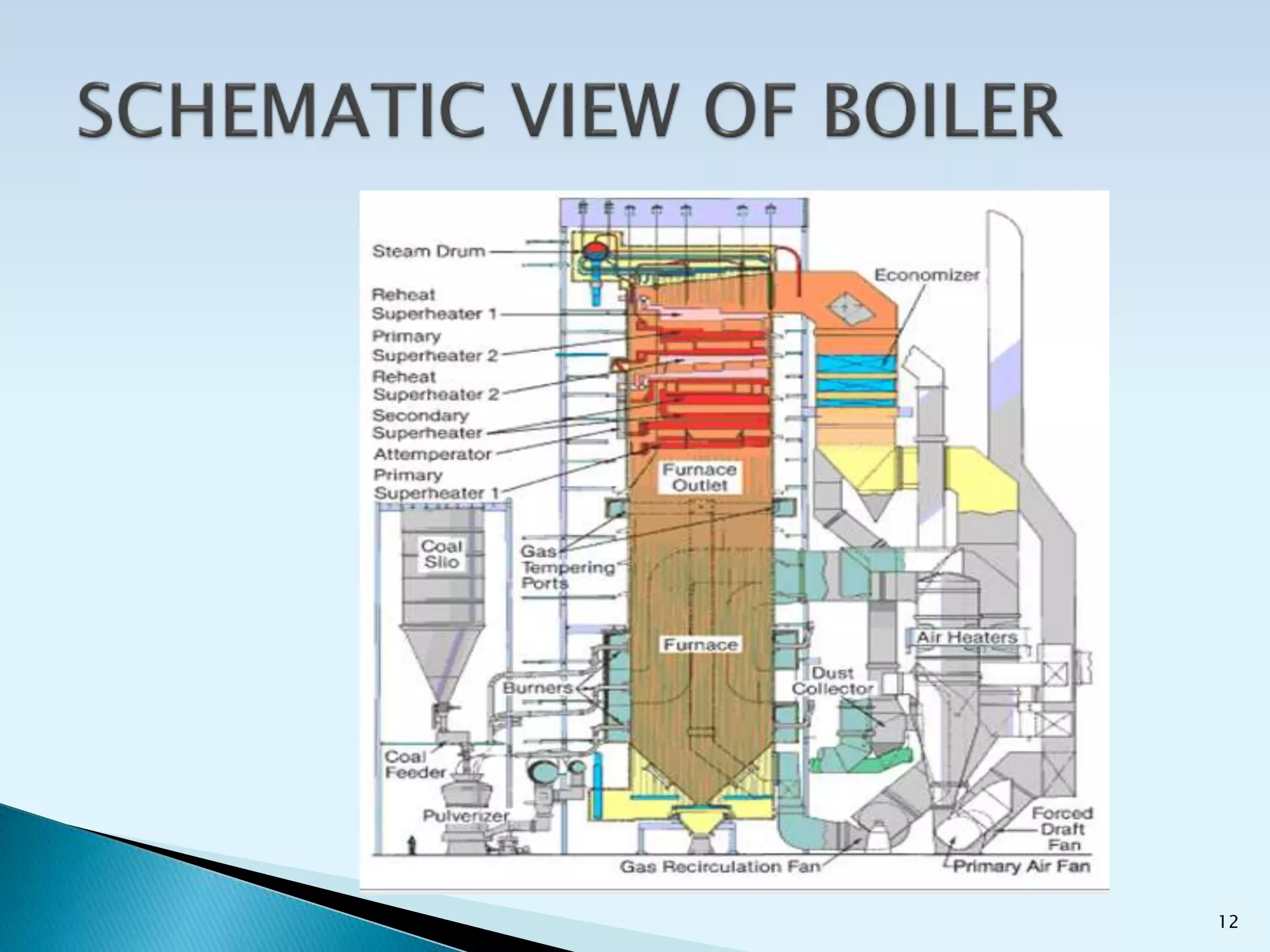
- Boiler components like water walls, drums, and superheaters are discussed. Steam is generated at high pressures and temperatures before powering turbines.
- Boiler reliability is critical but failures can occur due to issues like poor design


![Amardeep jadeja copy.ppt [autosaved]](https://cdn.slidesharecdn.com/ss_thumbnails/amardeepjadeja-copy-pptautosaved-111008011305-phpapp02-thumbnail.jpg?width=640&height=640&fit=bounds)


