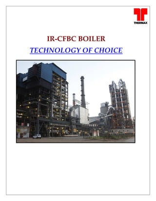
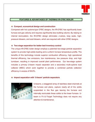
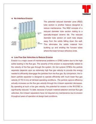
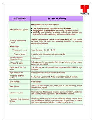
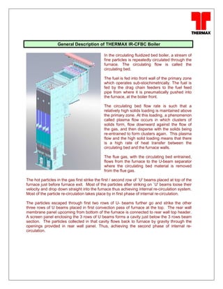
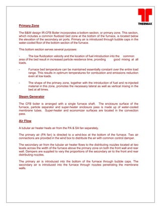
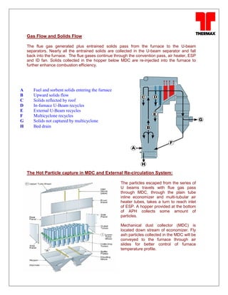
Thermax Limited is an Indian company established in 1966 that provides sustainable energy and environmental solutions. It offers integrated solutions for heating, cooling, power, water, and air pollution control. The document focuses on Thermax's internally circulating fluidized bed circulating boiler (IR-CFBC) technology. The IR-CFBC uses a unique two-stage particle separation system and U-beam impact separators to efficiently separate solids from flue gas. This compact design results in lower maintenance costs compared to conventional circulating fluidized bed boilers. The IR-CFBC also has advantages like high combustion efficiency, low emissions, and improved performance during variable and low loads.
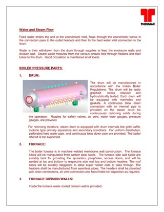


![Getting Started with Apache Spark: Big Data Made Simple [Free Meetup]](https://cdn.slidesharecdn.com/ss_thumbnails/apachesparkgettingstarted-260203175547-8361bcc3-thumbnail.jpg?width=640&height=640&fit=bounds)


