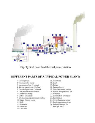
SlideShare a Scribd company logo
REPORT ON
SUMMER INDUSTRIALTRAINING
AT
SUPER THERMAL POWER
PLANT, BARH
PRESENTED BY:
ABHISHEK CHAUDHARY
BACHLOR OF ENGINEERING
ELECTRONICS & TELECOMMUNICATION (III YEAR)
BHARATI VIDYAPEETH COLLEGE OF ENGINEERING
INTRODUCTION
A thermal power station is a power plant in which chemical
Energy of fuel, which is either Coal, Oil, gas, etc. is converted to
Electrical Energy. Water is heated by burning coal and fuel in a
Boiler or steam generator, which turns into steam and the
generated steam spins a steam turbine which drives an electrical
generator called turbo generator. After it passes through the
turbine, the steam is condensed in a condenser and recycled to
where it was heated; this is known as a Rankine cycle. The
greatest variation in the design of thermal power stations is due to
the different fuel sources. Almost all coal, nuclear, geothermal,
solar thermal, electric and waste incineration plants, as well as
many natural gas power plants are thermal. Electric power plants
typically use three-phase or individual-phase electrical generators
to produce alternating current (AC) electric power at a frequency
of 50 Hz or 60 Hz (Hertz, which is an AC sine wave per second)
depending on its location in the world.
Michael Faraday discovered-if
an electric conductor, like a
copper wire, is moved Through
a magnetic field, electric current
will flow (or "be induced") in the
conductor. So the mechanical
energy of the moving wire is
converted into the electric
energy of the current that flows
in the wire.
Fig. Typical coal-fired thermal power station
DIFFERENT PARTS OF A TYPICAL POWER PLANT:
1. Cooling tower 15. Coal hopp
2. Cooling water pump 16. Coal
3. transmission line (3-phase) 17. Boiler
4. Step-up transformer (3-phase) 18. Bottom hopper
5. Electrical generator (3-phase) 19. Superheat steam turbine
6. Low pressure steam turbine 20. Forced draught(draft) fan
7. Condensate pump 21. Reheater
8. Surface condenser 22. Combustion air intake
9. Intermediate pressure steam turbine 23. Economiser
10. Steam Control valve 24. Air preheaterpulverizer
11. High 25. Precipitator steam drum
12. Deaerator 26. Induced draught fan
13. Feedwater 27. Flue gas stack
14. Coal conv
“ENERGY IS CONSERVED AND IT CAN
NEITHER BE CREATED NOR BE DESTROYED”
DIFFERENT SOURCE POWER GENERATION
A BRIEF INTRODUCTION TO NTPC
• The largest power generation company in India under Central
Government
• 16 coal based and 7 gas based power plants owned by NTPC
• 7 coal & gas based projects owned by JVs of NTPC
• Current installed capacity – 39,174 MW
• Capacity added during XII Plan (Mar’12 onward) – 2,160 MW
• At present 19 projects are under construction
BARH SUPER THERMAL POWER PROJECT (3300 MW)
• Location : 6 km East of Barh town,
• District Patna, Bihar
• Nearest Airport : Patna (75 km from site)
• Railway Stn: Barh Railway Station
• Capacity : Stage I: 3x660 MW
Stage II: 2x660 MW
• Land : Already acquired for both
the stages
SALIENT FEATURES
• Coal Requirement : 17 MTPA
• Source of Coal : North Karanpura Coalfields
• Source of Water : River Ganges
• Beneficiaries : Bihar & other states of
Eastern Region
Barh Super Thermal Power Project (3300 MW)
Comparison of Barh stage -I & II
Barh Stage-I
(3x660 MW)
Barh Stage-II
(2x660 MW)
Once Through Once Through
Vertical Tube Spiral Tube
T-Type Conventional two-pass
Balance Draft Balance Draft
Height: 108.85 Height: 104.4
Burners: 40 burners (20
on both sides) arranged
in five tiers
Burners: 36 burners at 9
elevations on all the four
corners
TYPICAL SCHEME OF COAL FIRED POWER PLANTS
RANKINE CYCLE:
The Rankine cycle is a model that is used to predict the
performance of steam turbine systems. The Rankine cycle is an
idealized thermodynamic cycle of a heat engine that converts heat
into mechanical work. The heat is supplied externally to a closed
loop, which usually uses water as the working fluid. It is named
after William John Macquorn Rankine, a Scottish polymath and
Glasgow University professor.
The Rankine cycle closely describes the process by which steam-
operated heat engines commonly found in thermal power
generation plants generate power. The heat sources used in these
power plants are usually nuclear fission or the combustion of
fossil fuels such as coal, natural gas, and oil.
The efficiency of the Rankine cycle is limited by the high heat of
vaporization of the working fluid. Also, unless the pressure and
temperature reach super critical levels in the steam boiler, the
temperature range the cycle can operate over is quite small: steam
turbine entry temperatures are typically around 565°C and steam
condenser temperatures are around 30°C. This gives a theoretical
maximum Carnot efficiency for the steam turbine alone of about
63% compared with an actual overall thermal efficiency of up to
42% for a modern coal-fired power station. This low steam
turbine entry temperature (compared to a gas turbine) is why the
Rankine (steam) cycle is often used as a bottoming cycle to
recover otherwise rejected heat in combined-cycle gas turbine
power stations.
Rankine cycle with reheat
The purpose of a reheating cycle is to remove the moisture carried
by the steam at the final stages of the expansion process. In this
variation, two turbines work in series. The first accepts vapor
from the boiler at high pressure. After the vapor has passed
through the first turbine, it re-enters the boiler and is reheated
before passing through a second, lower-pressure, turbine. The
reheat temperatures are very close or equal to the inlet
temperatures, whereas the optimum reheat pressure needed is
only one fourth of the original boiler pressure. Among other
advantages, this prevents the vapor from condensing during its
expansion and thereby damaging the turbine blades, and improves
the efficiency of the cycle, because more of the heat flow into the
cycle occurs at higher temperature. The reheat cycle was first
introduced in the 1920s, but was not operational for long due to
technical difficulties. In the 1940s, it was reintroduced with the
increasing manufacture of high-pressure boilers, and eventually
double reheating was introduced in the 1950s. The idea behind
double reheating is to increase the average temperature. It was
observed that more than two stages of reheating are unnecessary,
since the next stage increases the cycle efficiency only half as
much as the preceding stage. Today, double reheating is
commonly used in power plants that operate under supercritical
pressure.
Regenerative Rankine cycle:
The regenerative Rankine cycle is so named because after
emerging from the condenser (possibly as a subcooled liquid) the
working fluid is heated by steam tapped from the hot portion of
the cycle. On the diagram shown, the fluid at 2 is mixed with the
fluid at 4 (both at the same pressure) to end up with the saturated
liquid at 7. This is called "direct contact heating". The
Regenerative Rankine cycle (with minor variants) is commonly
used in real power stations.
Another variation sends bleed steam from between turbine stages
to feedwater heaters to preheat the water on its way from the
condenser to the boiler. These heaters do not mix the input steam
and condensate, function as an ordinary tubular heat exchanger,
and are named "closed feedwater heaters".
Regeneration increases the cycle heat input temperature by
eliminating the addition of heat from the boiler/fuel source at the
relatively low feedwater temperatures that would exist without
regenerative feedwater heating. This improves the efficiency of
the cycle, as more of the heat flow into the cycle occurs at higher
temperature.
Super-critical vs Sub-critical
Comparison of Parameters
DIFFERENT PARTS AND THEIR FUNCTIONS:
 STEAM GENERATOR:
It refers to a furnace that burns the fossil fuel to boil water to
generate steam. A fossil fuel steam generator includes an
economizer, a steam drum, and the furnace with its steam
generating tubes and super heater coils. Necessary safety valves
are located at suitable points to avoid excessive boiler pressure.
 BOILER FURNACE:
“BOILER” MEANS ANY CLOSED VESSEL EXCEEDING
22.75 Liters IN CAPACITY WHICH IS USED FOR
GENERATING STEAM UNDER PRESSURE.
The water enters the boiler through a section in the convection
pass called the economizer. From the economizer it passes to the
steam drum. Once the water enters the steam drum it goes down
the down comers to the lower inlet water wall headers. From the
inlet headers the water rises through the water walls and is
eventually turned into steam due to the heat being generated by
the burners located on the front and rear waterwalls (typically).
Boiler no.4 &5 of NTPC, BARH
 SUPER HEATER:
Fossil fuel power plants can have a super heater and/or reheater
section in the steam generating furnace. After the steam is
conditioned by the drying equipment inside the steam drum, it is
piped from the upper drum area into tubes inside an area of the
furnace known as the superheater, which has an elaborate set up
of tubing where the steam vapor picks up more energy from hot
flue gases outside the tubing and its temperature is now
superheated above the saturation temperature. The superheated
steam is then piped through the main steam lines to the valves
before the high pressure turbine.
 REHEATER :
Power plant furnaces may have a reheater section containing
tubes heated by hot flue gases outside the tubes. Exhaust steam
from the high pressure turbine is rerouted to go inside the reheater
tubes to pickup more energy to go drive intermediate or lower
pressure turbines.
 FUEL PREPARATION :
In coal-fired power stations, the raw feed coal from the coal
storage area is first crushed into small pieces and then conveyed
to the coal feed hoppers at the boilers. The coal is next pulverized
into a very fine powder. Some power stations burn fuel oil rather
than coal Boilers in some power stations use processed natural
gas as their main fuel.
 STACKS(CHIMNEYS) :
The stacks are used to drive the flue gas out into the atmosphere.
But as the flue gas consists of a lot of ash it must be passed
through ESP to prevent pollution. The flue gas consists of CO2,
SO2 , moisture and various other gases. The height of chimneys
must be high to prevent spreading of the gases near the earth.
 AIR DEHEATERS:
Before passing the atmospheric air along with coal dust into the
boiler for formation of furnace, the gas, must be heated to a high
temperature. This must be done to prevent fall of temperature in
furnace. If the air has a low temperature it will absorb heat from
the furnace. Thus it will create a problem in maintaining the
temperature of boiler.
 FORCE DRAFT FANS (FD FANS) :
Force draft fans are present before boilers. Their main job is to
pull the air from the atmosphere pass it through deheaters and then
insert it into boilers.
The working of FD fan can be directly controlled by the C & I
department. The angle made by the blades with the shaft can be
changed , blade If the air pressure in the furnace tends to increase
then at once command is given to change the angle of the blades.
So, the air forced into the furnace can be decreased and pressure
can be balanced.
 INDUCED DRAFT FANS ( ID FANS ):
They are single stage, single suction, simply supported centrifugal
machines which can be used to handle fresh air as well hot air in
power plants. It is Present in between ESP and stack. Its rating is
1350 KW ,speed is 746 (rpm) and voltage is 6600 V.
FUNCTION: It is used to pull the flue gas (after freed from ash )
from the ESP into the chimney
BLADES IN CLOSED POSITION BLADES IN OPEN POSITION
 CONDENSER:
The surface condenser is a shell and tube heat exchanger in which
cooling water is circulated through the tubes. The exhaust steam
from the low pressure turbine enters the shell where it is cooled
and converted to condensate (water) by flowing over the tubes.
The condenser generally uses either circulating cooling water
from a cooling tower to reject waste heat to the atmosphere, or
once-through water from a river, lake or ocean.
 ELECTROSTATIC PRECIPITATOR ( ESP):
A very important part of the plant. The ESP is situated after the
boiler and before the stack. The Flue gas which is ejected from
the boiler cannot be released to the atmosphere as it contains a lot
of ash. It will lead to pollution. So it is passed through ESP. It
consists of two electrodes - emitting and collecting. The emitting
electrode is negatively charged and collecting electrode is
positive. Ash is collected on the collecting electrode. Rapping is
done from time to time to shake off the ash. The ash gets collected
in the hopper (bottom ash hopper) .Its consists of a pressure
conveying inlet. Air is pumped through it and a vacuum pump is
connected to the hopper to remove ash. This dry ash is sent to silo.
STEPS FOLOWED BY WATER TO CHANGE
TO STEAM -:
1. Water enters the boiler through the eco feed pipe which are
present at the bottom of the 2nd
pass. It enters the eco coils
through the stubs which are mounted on eco inlet header.
2. Water then climbs through eco coils to eco intermediate header
& then through eco hanger tubes to eco outlet header. Finally
it goes from eco outlet header through eco link to drum.
3. From drum the water through down comers goes to four nos.
bottom ring headers. From bottom ring headers through water
wall panels it climbs to top headers. Again from top headers
through riser tubes the wet saturated steam enters into the
drum.
4. Water from Drum comes to bottom water wall ring header
through vertical down comers. From ring headers it will rise
through water wall panels and absorb radiant heat. Mixture of
water and steam will reach top water wall headers above roof.
Water and steam will enter the drum by riser pipes and steam
and water will be separated.
5. The saturated steam will reach SHH 1 through SH connecting
pipes.
6. Steam passes through radiant roof tubes it will reach outlet
header SHH2.
7. The steam from SHH2 comes to SHH3 in the second pass.
8. Wielded panels on second pass will bring the steam to SH side
outlet header SHH4.
9. Steam from SHH4 will reach SH front inlet header SHH5.
Steam can now rise through two paths. It can rise through
supply pipes from SHH 5 to extended side wall inlet header
SHH6. It can also rise through front panels to SHH 7.
10.The steam from these headers reach SHH7 through connecting
Pipes flow will be flow through panels covering the rear roof and
rear wall to LTSH Inlet Header SHH9.
11.The steam from SHH9 passes through super heater lower,
middle and upper banks and will come to SHH 10 by SH terminal
tubes.
12.De super heater links are connected between SHH 10 and SHH
11.
13.Then steam from SHH 11 will pass through SH platen coil
assemblies and reach SHH 12.
14.Links are connected between SHH 12 and vertical spaced SH
inlet header SHH 13 from where steam will flow.
15.SHH 13 will allow the steam to pass through Final SH
assemblies to reach SHH 14.
16.The main steam line will further carry the steam to HP turbine
from either side of SHH 14. The steam that strikes the turbine
blades has a temperature of 156 kg/cm2 and a pressure of 540 C.
Turbine & Generator
USES OF CONTROL & INSTRUMENTATION
IN POWER PLANTS
Introduction:-
In a Thermal Power Station, Chemical Energy of fuel, which is either Coal
or Oil, is converted to Electrical Energy. Actually, this energy conversion
takes place in different stages.
Firstly, in Boiler, the chemical energy in fuel (Coal /Oil) is converted into
heat energy. During process of combustion, the carbon, sulphur etc
available in the fuel reacts with air and liberates heat & flue gases. This
heat is absorbed by the water of water-walls of the furnace and
generates steam (heat energy).
Secondly, in Turbine, this heat energy, in the form of steam, is converted
into mechanical energy.
And finally, in Generator, which is directly coupled with the turbine, this
mechanical energy is converted into electrical energy or electricity.
Therefore, a Thermal Power Plant/Station can be regarded as a Process
Industry. Now, for successful completion of the process, a good numbers
of process parameters (like steam pressure & temperature, drum level,
feed water flow, etc) need continuous monitoring, which demands
instruments.In a modern boiler of a Thermal Power Station, combustion
process is very fast due to high steaming rate with increased unit
capacity. More over, to reduce cost, the present boilers are operated at
maximum permissible temperature limit of its metal.Further, due to
small capacity Drum and high steam output to water storage ratio, the
modern boiler demands continuous water feeding and constant drum
water level. This is essential to prevent starvation of the boiler.To
prevent boiler explosions and flame failure, the furnace draft (pressure)
is to be maintained constant.All the above things indicate that the steam
pressure & temperature, drum water level, furnace draft etc is to be
maintained constant. In older and low capacity boiler, most of the above
parameters are maintained manually. But in modern boilers, due to high
process reaction rate, the control of various reactions mentioned above
is beyond the purview of human and hence necessitates automatic
control, which intern demands instrumentation.At present, from the
technical aspect of view, we are going through that Era when technology
reaches to the State of Art. In this Art of State era, a remarkable
revolution has takes place in the field of Instrumentation. Digital Control
System (DCS) has replaces the conventional instrumentation system.
Adaptation of DCS has creates a new era of instrumentation.Just like
other process plant, the instrumentation system of a thermal power
plant has two parts --- Measurement & Control.
Measurement part deals with the measurement of different parameters
of the process by deploying different sensor which is mainly known as
primary instrument and brings it (measured value) in the notice of
operating personnel by displaying it on indicator or recording it on
recorder or storing it in Data Acquisition System (DAS) or in some cases,
by generating audiovisual alarm signal & protective signal. Indicator,
Recorder & DAS are mainly known as secondary instrument.Sometimes,
primary instrument i.e. primary sensing device is termed as Transmitter
or Transducer. Transduction means the conversion of energy. So
Transducer is the device, which converts energy from one form to
another form.
Control part takes care for automatic/manual control of different
parameters of the process. Setter, error generator, controller (Mainly PI
controller. In some cases it may be PID controller), auto/manual station,
amplifier, electrical to pneumatic converter, positioner, actuator, etc.
are the main component of control part.
MEASUREMENT OF PROCESS PARAMETERS:
Normally, in Thermal Power Plant, different parameters like Pressure
(Gauge Pressure), Temperature, Flow, Level, Thermal Expansion,
Displacement etc at different point/part of the process are measured.
Measurements of these parameters are essential and required: -
(i)To Guide for operating personnel,
(ii) To operate the plant efficiently,
(iii) To test the performance of the plant
(iv) To record the history of the plant and
(v) To generate audio-visual alarm signal and or trip signal if required.
The said measurements are done by measuring system, which consists
of
(i) Primary Instrument or Sensor --- mainly Gauges, Transmitter etc, and
(ii) Secondary Instrument --- mainly Indicator, Recorder, Data
Acquisition System (DAS), etc.Depending upon the importance of the
parameter, which is to be measured, these instruments are
mounted/erected
(i) on Spot --- mainly Local Gauge (Pressure & Temperature),
Rotameter type Flow meter etc, (ii) on Local Panel or Instrument Rack -
-- mainly local panel gauge, local indicator, transmitter/transducer etc,
(ii) on Panel at Unit Control Room --- mainly Secondary instrument i.e.,
Recorder, Indicator, and DAS etc.
Pressure Measurement:
Pressure & Vacuum are the most common & important process
parameter of a thermal power plant. Pressure & Vacuum are measured
at so many points / parts of the process. Still Drum Pressure, Steam
Pressure at Turbine end, Deaerator Pressure, Furnace Pressure, Lube Oil
Pressure, Furnace Oil Pressure, Feed Water Pressure, Condenser
Vacuum are the most important process parameter.
Bourdon Tube Pressure Gauge, Diaphragm Pressure Gauge, Capsule
Pressure Gauge, Bellow Pressure Gauge, Electronics Pressure
Transmitter (Bourdon Tube, Bellow, Diaphragm or Capsule type) &
Kenotometer (For back pressure measurement. Here for Condenser
Vacuum measurement) are mainly used for measurement of Pressure &
Vacuum.
Depending upon the importance of the parameter, which is to be
measured, either Pressure Gauge or Electronics Transmitter is used for
measurement of that particular parameter.
The Electronics Pressure Transmitters, which are normally used in
thermal power station, are mainly either (i) Reluctance Type or (ii)
Capacitance Type. Now a day, Capacitance type transmitters are widely
used.
The Reluctance type transmitters, which are mainly used in thermal
power plant, operate either on the basis of LVDT (Linear Variable
Differential Transformer) principle or Force Balance principle.The output
of these transmitters is 1-0-1 Volts AC. Delta – pi transmitters of George
Kent, U. K, are based on Force Balance principle. The output of these
transmitters is 4 - 20 mA DC.Fuji and Rosemount make transmitters are
mainly Capacitance type. The output of these transmitters is 4 - 20 mA
D.C. Now a day, in a modern process plant, where modern
instrumentation system like DCS has replaces the conventional
instrumentation system, microprocessor based capacitance transmitters
are widely used. These transmitters are normally known as ‘Smart
Transmitter’. As per requirement of the user, the out put of these
transmitter may be conventional 4 - 20 mA D.C or conventional 4 - 20
mA D.C signal in Digital Form or both conventional signal and
conventional signal in digital form.
Pressure Gauge
Temperature Measurement: -
Temperature may be defined as Degree of Heat, where as heat is usually
taken to mean Quantity of Heat.Like pressure, temperature is also a most
important process parameter of a thermal power plant. Temperature is
measured at so many points / parts of the process. But steam
temperature, Drum temperature, SH & RH metal temperature, T/G Lube
Oil & Bearing Babbitt temperature, Generator Gas temperature, HPT
exhaust temperature etc has great importance in thermal power plant.
Depending upon the importance of the parameters, which is to be
measured, either Expansion thermometer or Change of state
thermometer or Radiation and Optical Pyrometer or Electrical method of
temperature detection system is normally used in thermal plant. Out of
above said thermometers, only Expansion thermometer and Electrical
type thermometer are widely used.
And for measurement of temperature at those points / parts of the
process, which are remote & critical from location point of view and / or
which demands accuracy, precision and remote transmission, are
normally measured by deploying Electrical method of temperature
detection system. Normally, K – type Thermocouple (TC), Copper
Resistance thermometers (CRT) and Platinum Resistance thermometers
(PRT) are widely used in a thermal power plant. By means of a suitable
apparatus, a change of temperature can be converted into a variable
electrical quantity i.e. voltage, current or resistance. TC, CRT & PRT
operates on the basis of this phenomenon.
Temperature gauge
Thermocouple (TC): When two dissimilar metals are welded together at
one end and then heated, a voltage, which can be measured and the
measured value can be calibrated in terms of temperature, is developed
on the free end. This phenomenon is known as the principle of
thermoelectricity.Commercial TC generates on the order of 20 – 50 mV
through the range of their operating temperature.
Thermocouple Thermocouple
Resistance Temperature Detector (RTD): The resistance of pure metallic
conductors increases with temperature and this change can be detected
electrically. RTD operates on the basis of this principle. It is a highly
accurate method of temperature measurement and particularly useful
for measurement of lower temperature scales down to – 400 OF and can
be used up to 1300 OF.
Radiation Pyrometer: The intensity of radiation energy emitted from the
surface of a body increases proportionally to the fourth (4th) power of
the absolute temperature of the body. Energy from the target (target
means a portion of the object whose temperature is to be measured) is
focussed on a thermopile (thermopile means a number of small TC
connected in series) by the pyrometer lens. The thermopile generates an
emf, which is proportional to the amount of energy falling on it.
Therefore, the emf is proportional to the temperature of the target. It is
normally used where atmospheres are detrimental to TC and cause
erratic measurement & short life.
Measurement of Level: -
In thermal power plant, measurement of level is essential for the
purpose of safe and efficient operation of the plant. For the purpose of
co-ordination and control, level measurement is also required. In
thermal power station, measurement of level is carried out for liquid and
solid. The coal level in the pulverize coal bunkers are measured, which
are the example of measurement of level of solid. Measurement of Boiler
drum water level, Deaerator water level, Condenser Hot well level, etc is
the example of measurement of level of liquid.
When liquid level is monitored for the purpose of guidance for operating
personnel, level is measured by sight glass method. These are normally
known as Direct Gauge Glass. Local gauges of Deaerator water level,
Condenser Hot well level, Boiler Drum water level, HP heaters & LP
heaters shell water level (HPH’s & LPH’s drip level), Lube oil tank level,
etc falls under this case.In thermal power plant, liquid level is also
measured to generate audiovisual alarm signal as well as protective
signal when the measured level falls below or raises above a preset value
(level).
Level transmitter Radar type level transmitter
Measurement of Flow: -
Like pressure, temperature and level, flow is also most important process
parameter, which is monitored continuously for purpose of Control, Co-
ordination and Safe Operation of the process. In a thermal power plant,
flow of liquid as well as flow of solid is also measured for periodic as well
as for on line efficiency calculation, which plays an important role in the
modern concept of power plant operation, of the process.Normally, rate
flow instruments are widely used for measurement of flow of Steam,
Feed Water, Spray Water, Fuel Oil, Air, D. M. Water etc and integrators
are used for measurement of flow of Coal. Coal flow integrators are
basically required to know the coal consumption, coal stock and to assess
the performance of the unit and to deal with supplier.Normally, for
remote indication and control, differential pressure transmitters (dp
transmitter) are widely used for measurement fluid flow. But, when local
indication of fluid flow are required for guidance of operating personnel
then ‘Rote-meter’ or / and ‘Turbine flow meter’ are used for
measurements of fluid flow.
Rota- meter D.P. Transmitter
Analytical Instruments or Analyser:-
Unlike the aforesaid instruments, where measurement is done by
displacement and mechanical means – based on physical properties,
some instruments are used to analyse the sample – based on chemical
heating or paramagnetic effects. Such instruments are normally termed
as ‘Analytical Instruments or Analyser’.In a modern thermal power plant,
analytical instruments are essential to measure ‘Oxygen in Flue Gas’,
‘Dissolved Oxygen in Feed Water’, ‘Conductivity of Feed Water’ at
different points of the process or circuit, ‘PH of Feed Water’ at different
points of the process or circuit, ‘Silica content of Feed Water’ and ‘Purity
of Hydrogen’ in generator casing.
CONTROL OF PROCESS PARAMETERS
We know that in a thermal power station, controlling of some process
parameters are essential for safe and economic operation of the unit or
station.The controls in a thermal power station may be Pneumatic or
Electronic. In the past (few decade ago), Pneumatic Control System was
widely used for controlling of the process parameters of process
industry. After that, with advancement in electronic field, Electronic
Control System made a favourable footing in some cases where more
complex & more number of control functions are involved. But, now a
day, with further advancement in electronic field & introduction of
computer, Electronic Control System is widely used in almost all modern
thermal power stations.
The control system of a process
industry consists of the
followings:
TRANSDUCER : It converts the
process variable, which is to be
controlled, into an equivalent
electrical or pneumatic signal.
Setter : It sets the desired value, which is to be maintained, of the
process variable.
Error Detector : The actual value, which is received from the
transducer, of process variable is compared with the pre-set value,
which is received from the setter, and the deviation, if any, is sent to
the controller as output.
Controller : The error signal is amplified on the basis of the amplitude
and polarity of the error signal, corrective signal is sent to the
Auto/Manual station as output.
Auto / Manual Station: Practically, it is a changeover switch or selector
switch. If selected for Auto (Auto Operation) then the corrective signal of
the Controller directly goes to the Final Control Element. Now, when
selected for Manual (Manual Operation) then the corrective signal of the
Controller is blocked and the operating personnel has to adjust the
corrective signal for the Final Control Element manually as and when
deviation occurs.
Final Control Element: It is either a Pneumatic Motor (Diaphragm or
Power Cylinder) or a Reversible Electric Motor or a Hydraulic Motor
(Piston and Cylinder assembly). It is directly coupled (by mechanical link)
with Control Valve or Control Vane or Control Damper and operates as
per the Auto Signal or Manual signal which it receives from Auto /
Manual station. Practically, it is the drive of Control Valve or Control Vane
or Control Damper of the process.
Valve or Vane or Damper: Practically, these are gate or door of the
different part of the process whose opening is controlled for controlling
the process parameter. It is mechanically coupled with the Final Control
Element and driven by the Final Control Element.
Position Indicator: Basically, it is a indicator whose scale is calibrated
from 0% to 100%. It shows the actual position (Opening) of the Control
Valve or Control Vane or Control Damper of the process. Practically,
position feedback transmitter (or some suitable means) converts the
movement of Control Valve or Control Vane or Control Damper to an
equivalent electrical signal, which is measured by this position Indicator.
CONCLUSION
In a process plant, following types of instruments are applied for
the desired purposes:-
The indicating instruments are provided to monitor the process
for safe and efficient operation. The recording instruments
(Recorder, data Acquisition system) are provided to study the
performance of the unit and to suggest the operating personnel
regarding the correct way of operation. The recording instruments
are essential to build up the history of the unit and play an
important role in modification work for further improvement of
performance. The signaling or annunciating instruments alerts
the operating personnel in the control room at right time to take
corrective action for safe and efficient operation. The controlling
instruments regulate the process to maintain the designed
operating parameters.
The instruments are, therefore, designed
and provided at suitable locations of the power station safe,
efficient and economic operation. These instruments are
connected to the automated systems and can be operated from a
remote location either manually or automatically by the systems.
report final

More Related Content

What's hot

Steam Power Plants
Steam Power PlantsSteam Power Plants
Steam Power Plants
Geo Jovin Vinister
 
Steam power plant
Steam power plantSteam power plant
Steam power plant
MalikURock
 
Power plant, Power Station and types of power plant
Power plant, Power Station and types of power plantPower plant, Power Station and types of power plant
Power plant, Power Station and types of power plant
Poornima Group of Institutions, Jaipur
 
A seminar on thermal p.p
A seminar on thermal p.pA seminar on thermal p.p
A seminar on thermal p.pDivyansh Soni
 
Thermalpwrplant 110924082908-phpapp02
Thermalpwrplant 110924082908-phpapp02Thermalpwrplant 110924082908-phpapp02
Thermalpwrplant 110924082908-phpapp02arvind singh rathore
 
Coal based thermal power plant
Coal based thermal power plant Coal based thermal power plant
Coal based thermal power plant
Eklavya Sharma
 
Thermal power plant
Thermal power plantThermal power plant
Thermal power plant
Ashvani Shukla
 
STEAM POWER PLANT
STEAM POWER PLANTSTEAM POWER PLANT
STEAM POWER PLANT
Pratheeka p nair
 
Thermal power plant
Thermal power plantThermal power plant
Thermal power plant
Rabi Kumar
 
Best steam power plant
Best steam power plant Best steam power plant
Best steam power plant Enamul Khan
 
Thermal power plant
Thermal power plantThermal power plant
Thermal power plantfoxycrow
 
Power plant
Power plantPower plant
Power plant
Shubham Gupta
 
Thermal Power Plant - Full Detail About Plant and Parts (Also Contain Animate...
Thermal Power Plant - Full Detail About Plant and Parts (Also Contain Animate...Thermal Power Plant - Full Detail About Plant and Parts (Also Contain Animate...
Thermal Power Plant - Full Detail About Plant and Parts (Also Contain Animate...
Shubham Thakur
 
power plant engineering Unit 1
power plant engineering Unit 1power plant engineering Unit 1
power plant engineering Unit 1
BHUPALAM VENKATESH
 
thermal and nuclear power plant
 thermal and nuclear power plant thermal and nuclear power plant
thermal and nuclear power plant
Akash soni
 
Power Generation and Steam power plant
Power Generation and Steam power plantPower Generation and Steam power plant
Power Generation and Steam power plant
Taimoor Muzaffar Gondal
 
Steam power plant
Steam power plantSteam power plant
Steam power plant
Niraj Solanki
 
Thermal Power Plant
Thermal Power PlantThermal Power Plant
Thermal Power Plant
Manish Kumar
 
HPGCL Thermal power plant Summer Training report
HPGCL Thermal power plant Summer Training reportHPGCL Thermal power plant Summer Training report
HPGCL Thermal power plant Summer Training report
Rakesh Gothwal
 
Talwandi sabo power plant (t
Talwandi sabo power plant (tTalwandi sabo power plant (t
Talwandi sabo power plant (t
21403515
 

What's hot (20)

Steam Power Plants
Steam Power PlantsSteam Power Plants
Steam Power Plants
 
Steam power plant
Steam power plantSteam power plant
Steam power plant
 
Power plant, Power Station and types of power plant
Power plant, Power Station and types of power plantPower plant, Power Station and types of power plant
Power plant, Power Station and types of power plant
 
A seminar on thermal p.p
A seminar on thermal p.pA seminar on thermal p.p
A seminar on thermal p.p
 
Thermalpwrplant 110924082908-phpapp02
Thermalpwrplant 110924082908-phpapp02Thermalpwrplant 110924082908-phpapp02
Thermalpwrplant 110924082908-phpapp02
 
Coal based thermal power plant
Coal based thermal power plant Coal based thermal power plant
Coal based thermal power plant
 
Thermal power plant
Thermal power plantThermal power plant
Thermal power plant
 
STEAM POWER PLANT
STEAM POWER PLANTSTEAM POWER PLANT
STEAM POWER PLANT
 
Thermal power plant
Thermal power plantThermal power plant
Thermal power plant
 
Best steam power plant
Best steam power plant Best steam power plant
Best steam power plant
 
Thermal power plant
Thermal power plantThermal power plant
Thermal power plant
 
Power plant
Power plantPower plant
Power plant
 
Thermal Power Plant - Full Detail About Plant and Parts (Also Contain Animate...
Thermal Power Plant - Full Detail About Plant and Parts (Also Contain Animate...Thermal Power Plant - Full Detail About Plant and Parts (Also Contain Animate...
Thermal Power Plant - Full Detail About Plant and Parts (Also Contain Animate...
 
power plant engineering Unit 1
power plant engineering Unit 1power plant engineering Unit 1
power plant engineering Unit 1
 
thermal and nuclear power plant
 thermal and nuclear power plant thermal and nuclear power plant
thermal and nuclear power plant
 
Power Generation and Steam power plant
Power Generation and Steam power plantPower Generation and Steam power plant
Power Generation and Steam power plant
 
Steam power plant
Steam power plantSteam power plant
Steam power plant
 
Thermal Power Plant
Thermal Power PlantThermal Power Plant
Thermal Power Plant
 
HPGCL Thermal power plant Summer Training report
HPGCL Thermal power plant Summer Training reportHPGCL Thermal power plant Summer Training report
HPGCL Thermal power plant Summer Training report
 
Talwandi sabo power plant (t
Talwandi sabo power plant (tTalwandi sabo power plant (t
Talwandi sabo power plant (t
 

Similar to report final

Chapter 10 lecture
Chapter 10 lectureChapter 10 lecture
Chapter 10 lecture
Senthil Kumar
 
Thermal power plant
Thermal power plantThermal power plant
Thermal power plant
Shikhar Sodhani
 
SUMMER INTERNSHIP(INDUSTRAIL REPORT) ON THERMAL POWER PLANT
SUMMER INTERNSHIP(INDUSTRAIL REPORT) ON THERMAL POWER PLANT SUMMER INTERNSHIP(INDUSTRAIL REPORT) ON THERMAL POWER PLANT
SUMMER INTERNSHIP(INDUSTRAIL REPORT) ON THERMAL POWER PLANT
Amit Gupta
 
Power cycles
Power cyclesPower cycles
Power cycles
Himanshu Rajput
 
Thermal power plant
Thermal power plantThermal power plant
Thermal power plant
Viren Patel
 
THERMAL POWER PLANT TRAINING INDUSTRIAL VISIT REPORT
THERMAL POWER PLANT TRAINING INDUSTRIAL VISIT REPORTTHERMAL POWER PLANT TRAINING INDUSTRIAL VISIT REPORT
THERMAL POWER PLANT TRAINING INDUSTRIAL VISIT REPORT
Prasant Kumar
 
Industrial training at NTPC Shaktinagar
Industrial training at NTPC ShaktinagarIndustrial training at NTPC Shaktinagar
Industrial training at NTPC Shaktinagar
Rishikesh .
 
Thermal power plant Khedr, Hisar, Haryana
Thermal power plant Khedr, Hisar, HaryanaThermal power plant Khedr, Hisar, Haryana
Thermal power plant Khedr, Hisar, HaryanaEesha Gupta
 
Kota super thermal power plant,kstps ppt,RTU
Kota super thermal power plant,kstps ppt,RTUKota super thermal power plant,kstps ppt,RTU
Kota super thermal power plant,kstps ppt,RTU
Manohar Nagar
 
Mtps ppt
Mtps pptMtps ppt
Mtps ppt
sourabhgnit
 
Thermal power plant
Thermal power plantThermal power plant
Thermal power plant
Anish Kumar Gupta
 
steam turbine[1] (3).pptxshshshhhshshshh
steam turbine[1] (3).pptxshshshhhshshshhsteam turbine[1] (3).pptxshshshhhshshshh
steam turbine[1] (3).pptxshshshhhshshshh
AzizAlabad
 
POWER PLANT.pdf
POWER PLANT.pdfPOWER PLANT.pdf
POWER PLANT.pdf
MishraAnup1
 
NTPC Project KORBA(SUPER THEMAL POWER PLANT)
NTPC Project KORBA(SUPER THEMAL POWER PLANT)NTPC Project KORBA(SUPER THEMAL POWER PLANT)
NTPC Project KORBA(SUPER THEMAL POWER PLANT)Rajan Kumar Choudhary
 
Thermal power plant
Thermal power plantThermal power plant
Thermal power plant
Vinay Garg
 
Overview of ktps v station (2×250 mw)
Overview of ktps v station (2×250 mw)Overview of ktps v station (2×250 mw)
Overview of ktps v station (2×250 mw)
Srikanta Sinha
 
Training Report 7121113526
Training Report 7121113526Training Report 7121113526
Training Report 7121113526Kshitij Sharma
 
Modern thermal power plant
Modern thermal power plantModern thermal power plant
Modern thermal power plant
Taral Soliya
 
Thermal Power Plant
Thermal  Power  PlantThermal  Power  Plant
Thermal Power Plant
Sandip De
 
NTPC ,sipat voccational training
NTPC ,sipat voccational trainingNTPC ,sipat voccational training
NTPC ,sipat voccational training
bhumit1
 

Similar to report final (20)

Chapter 10 lecture
Chapter 10 lectureChapter 10 lecture
Chapter 10 lecture
 
Thermal power plant
Thermal power plantThermal power plant
Thermal power plant
 
SUMMER INTERNSHIP(INDUSTRAIL REPORT) ON THERMAL POWER PLANT
SUMMER INTERNSHIP(INDUSTRAIL REPORT) ON THERMAL POWER PLANT SUMMER INTERNSHIP(INDUSTRAIL REPORT) ON THERMAL POWER PLANT
SUMMER INTERNSHIP(INDUSTRAIL REPORT) ON THERMAL POWER PLANT
 
Power cycles
Power cyclesPower cycles
Power cycles
 
Thermal power plant
Thermal power plantThermal power plant
Thermal power plant
 
THERMAL POWER PLANT TRAINING INDUSTRIAL VISIT REPORT
THERMAL POWER PLANT TRAINING INDUSTRIAL VISIT REPORTTHERMAL POWER PLANT TRAINING INDUSTRIAL VISIT REPORT
THERMAL POWER PLANT TRAINING INDUSTRIAL VISIT REPORT
 
Industrial training at NTPC Shaktinagar
Industrial training at NTPC ShaktinagarIndustrial training at NTPC Shaktinagar
Industrial training at NTPC Shaktinagar
 
Thermal power plant Khedr, Hisar, Haryana
Thermal power plant Khedr, Hisar, HaryanaThermal power plant Khedr, Hisar, Haryana
Thermal power plant Khedr, Hisar, Haryana
 
Kota super thermal power plant,kstps ppt,RTU
Kota super thermal power plant,kstps ppt,RTUKota super thermal power plant,kstps ppt,RTU
Kota super thermal power plant,kstps ppt,RTU
 
Mtps ppt
Mtps pptMtps ppt
Mtps ppt
 
Thermal power plant
Thermal power plantThermal power plant
Thermal power plant
 
steam turbine[1] (3).pptxshshshhhshshshh
steam turbine[1] (3).pptxshshshhhshshshhsteam turbine[1] (3).pptxshshshhhshshshh
steam turbine[1] (3).pptxshshshhhshshshh
 
POWER PLANT.pdf
POWER PLANT.pdfPOWER PLANT.pdf
POWER PLANT.pdf
 
NTPC Project KORBA(SUPER THEMAL POWER PLANT)
NTPC Project KORBA(SUPER THEMAL POWER PLANT)NTPC Project KORBA(SUPER THEMAL POWER PLANT)
NTPC Project KORBA(SUPER THEMAL POWER PLANT)
 
Thermal power plant
Thermal power plantThermal power plant
Thermal power plant
 
Overview of ktps v station (2×250 mw)
Overview of ktps v station (2×250 mw)Overview of ktps v station (2×250 mw)
Overview of ktps v station (2×250 mw)
 
Training Report 7121113526
Training Report 7121113526Training Report 7121113526
Training Report 7121113526
 
Modern thermal power plant
Modern thermal power plantModern thermal power plant
Modern thermal power plant
 
Thermal Power Plant
Thermal  Power  PlantThermal  Power  Plant
Thermal Power Plant
 
NTPC ,sipat voccational training
NTPC ,sipat voccational trainingNTPC ,sipat voccational training
NTPC ,sipat voccational training
 

report final

  • 1.
  • 2. REPORT ON SUMMER INDUSTRIALTRAINING AT SUPER THERMAL POWER PLANT, BARH PRESENTED BY: ABHISHEK CHAUDHARY BACHLOR OF ENGINEERING ELECTRONICS & TELECOMMUNICATION (III YEAR) BHARATI VIDYAPEETH COLLEGE OF ENGINEERING
  • 3. INTRODUCTION A thermal power station is a power plant in which chemical Energy of fuel, which is either Coal, Oil, gas, etc. is converted to Electrical Energy. Water is heated by burning coal and fuel in a Boiler or steam generator, which turns into steam and the generated steam spins a steam turbine which drives an electrical generator called turbo generator. After it passes through the turbine, the steam is condensed in a condenser and recycled to where it was heated; this is known as a Rankine cycle. The greatest variation in the design of thermal power stations is due to the different fuel sources. Almost all coal, nuclear, geothermal, solar thermal, electric and waste incineration plants, as well as many natural gas power plants are thermal. Electric power plants typically use three-phase or individual-phase electrical generators to produce alternating current (AC) electric power at a frequency of 50 Hz or 60 Hz (Hertz, which is an AC sine wave per second) depending on its location in the world. Michael Faraday discovered-if an electric conductor, like a copper wire, is moved Through a magnetic field, electric current will flow (or "be induced") in the conductor. So the mechanical energy of the moving wire is converted into the electric energy of the current that flows in the wire.
  • 4. Fig. Typical coal-fired thermal power station DIFFERENT PARTS OF A TYPICAL POWER PLANT: 1. Cooling tower 15. Coal hopp 2. Cooling water pump 16. Coal 3. transmission line (3-phase) 17. Boiler 4. Step-up transformer (3-phase) 18. Bottom hopper 5. Electrical generator (3-phase) 19. Superheat steam turbine 6. Low pressure steam turbine 20. Forced draught(draft) fan 7. Condensate pump 21. Reheater 8. Surface condenser 22. Combustion air intake 9. Intermediate pressure steam turbine 23. Economiser 10. Steam Control valve 24. Air preheaterpulverizer 11. High 25. Precipitator steam drum 12. Deaerator 26. Induced draught fan 13. Feedwater 27. Flue gas stack 14. Coal conv
  • 5. “ENERGY IS CONSERVED AND IT CAN NEITHER BE CREATED NOR BE DESTROYED” DIFFERENT SOURCE POWER GENERATION
  • 6. A BRIEF INTRODUCTION TO NTPC • The largest power generation company in India under Central Government • 16 coal based and 7 gas based power plants owned by NTPC • 7 coal & gas based projects owned by JVs of NTPC • Current installed capacity – 39,174 MW • Capacity added during XII Plan (Mar’12 onward) – 2,160 MW • At present 19 projects are under construction
  • 7. BARH SUPER THERMAL POWER PROJECT (3300 MW) • Location : 6 km East of Barh town, • District Patna, Bihar • Nearest Airport : Patna (75 km from site) • Railway Stn: Barh Railway Station • Capacity : Stage I: 3x660 MW Stage II: 2x660 MW • Land : Already acquired for both the stages SALIENT FEATURES • Coal Requirement : 17 MTPA • Source of Coal : North Karanpura Coalfields • Source of Water : River Ganges • Beneficiaries : Bihar & other states of Eastern Region
  • 8. Barh Super Thermal Power Project (3300 MW)
  • 9. Comparison of Barh stage -I & II Barh Stage-I (3x660 MW) Barh Stage-II (2x660 MW) Once Through Once Through Vertical Tube Spiral Tube T-Type Conventional two-pass Balance Draft Balance Draft Height: 108.85 Height: 104.4 Burners: 40 burners (20 on both sides) arranged in five tiers Burners: 36 burners at 9 elevations on all the four corners
  • 10. TYPICAL SCHEME OF COAL FIRED POWER PLANTS RANKINE CYCLE: The Rankine cycle is a model that is used to predict the performance of steam turbine systems. The Rankine cycle is an idealized thermodynamic cycle of a heat engine that converts heat into mechanical work. The heat is supplied externally to a closed loop, which usually uses water as the working fluid. It is named after William John Macquorn Rankine, a Scottish polymath and Glasgow University professor. The Rankine cycle closely describes the process by which steam- operated heat engines commonly found in thermal power generation plants generate power. The heat sources used in these
  • 11. power plants are usually nuclear fission or the combustion of fossil fuels such as coal, natural gas, and oil. The efficiency of the Rankine cycle is limited by the high heat of vaporization of the working fluid. Also, unless the pressure and temperature reach super critical levels in the steam boiler, the temperature range the cycle can operate over is quite small: steam turbine entry temperatures are typically around 565°C and steam condenser temperatures are around 30°C. This gives a theoretical maximum Carnot efficiency for the steam turbine alone of about 63% compared with an actual overall thermal efficiency of up to 42% for a modern coal-fired power station. This low steam turbine entry temperature (compared to a gas turbine) is why the Rankine (steam) cycle is often used as a bottoming cycle to
  • 12. recover otherwise rejected heat in combined-cycle gas turbine power stations. Rankine cycle with reheat The purpose of a reheating cycle is to remove the moisture carried by the steam at the final stages of the expansion process. In this variation, two turbines work in series. The first accepts vapor from the boiler at high pressure. After the vapor has passed through the first turbine, it re-enters the boiler and is reheated before passing through a second, lower-pressure, turbine. The reheat temperatures are very close or equal to the inlet temperatures, whereas the optimum reheat pressure needed is only one fourth of the original boiler pressure. Among other
  • 13. advantages, this prevents the vapor from condensing during its expansion and thereby damaging the turbine blades, and improves the efficiency of the cycle, because more of the heat flow into the cycle occurs at higher temperature. The reheat cycle was first introduced in the 1920s, but was not operational for long due to technical difficulties. In the 1940s, it was reintroduced with the increasing manufacture of high-pressure boilers, and eventually double reheating was introduced in the 1950s. The idea behind double reheating is to increase the average temperature. It was observed that more than two stages of reheating are unnecessary, since the next stage increases the cycle efficiency only half as much as the preceding stage. Today, double reheating is commonly used in power plants that operate under supercritical pressure. Regenerative Rankine cycle:
  • 14. The regenerative Rankine cycle is so named because after emerging from the condenser (possibly as a subcooled liquid) the working fluid is heated by steam tapped from the hot portion of the cycle. On the diagram shown, the fluid at 2 is mixed with the fluid at 4 (both at the same pressure) to end up with the saturated liquid at 7. This is called "direct contact heating". The Regenerative Rankine cycle (with minor variants) is commonly used in real power stations. Another variation sends bleed steam from between turbine stages to feedwater heaters to preheat the water on its way from the condenser to the boiler. These heaters do not mix the input steam and condensate, function as an ordinary tubular heat exchanger, and are named "closed feedwater heaters". Regeneration increases the cycle heat input temperature by eliminating the addition of heat from the boiler/fuel source at the relatively low feedwater temperatures that would exist without regenerative feedwater heating. This improves the efficiency of the cycle, as more of the heat flow into the cycle occurs at higher temperature.
  • 16. DIFFERENT PARTS AND THEIR FUNCTIONS:  STEAM GENERATOR: It refers to a furnace that burns the fossil fuel to boil water to generate steam. A fossil fuel steam generator includes an economizer, a steam drum, and the furnace with its steam generating tubes and super heater coils. Necessary safety valves are located at suitable points to avoid excessive boiler pressure.  BOILER FURNACE: “BOILER” MEANS ANY CLOSED VESSEL EXCEEDING 22.75 Liters IN CAPACITY WHICH IS USED FOR GENERATING STEAM UNDER PRESSURE. The water enters the boiler through a section in the convection pass called the economizer. From the economizer it passes to the steam drum. Once the water enters the steam drum it goes down the down comers to the lower inlet water wall headers. From the inlet headers the water rises through the water walls and is eventually turned into steam due to the heat being generated by the burners located on the front and rear waterwalls (typically).
  • 17. Boiler no.4 &5 of NTPC, BARH  SUPER HEATER: Fossil fuel power plants can have a super heater and/or reheater section in the steam generating furnace. After the steam is conditioned by the drying equipment inside the steam drum, it is piped from the upper drum area into tubes inside an area of the furnace known as the superheater, which has an elaborate set up of tubing where the steam vapor picks up more energy from hot flue gases outside the tubing and its temperature is now superheated above the saturation temperature. The superheated steam is then piped through the main steam lines to the valves before the high pressure turbine.
  • 18.  REHEATER : Power plant furnaces may have a reheater section containing tubes heated by hot flue gases outside the tubes. Exhaust steam from the high pressure turbine is rerouted to go inside the reheater tubes to pickup more energy to go drive intermediate or lower pressure turbines.  FUEL PREPARATION : In coal-fired power stations, the raw feed coal from the coal storage area is first crushed into small pieces and then conveyed to the coal feed hoppers at the boilers. The coal is next pulverized into a very fine powder. Some power stations burn fuel oil rather than coal Boilers in some power stations use processed natural gas as their main fuel.  STACKS(CHIMNEYS) : The stacks are used to drive the flue gas out into the atmosphere. But as the flue gas consists of a lot of ash it must be passed through ESP to prevent pollution. The flue gas consists of CO2, SO2 , moisture and various other gases. The height of chimneys must be high to prevent spreading of the gases near the earth.
  • 19.  AIR DEHEATERS: Before passing the atmospheric air along with coal dust into the boiler for formation of furnace, the gas, must be heated to a high temperature. This must be done to prevent fall of temperature in furnace. If the air has a low temperature it will absorb heat from the furnace. Thus it will create a problem in maintaining the temperature of boiler.  FORCE DRAFT FANS (FD FANS) : Force draft fans are present before boilers. Their main job is to pull the air from the atmosphere pass it through deheaters and then insert it into boilers. The working of FD fan can be directly controlled by the C & I department. The angle made by the blades with the shaft can be changed , blade If the air pressure in the furnace tends to increase then at once command is given to change the angle of the blades. So, the air forced into the furnace can be decreased and pressure can be balanced.  INDUCED DRAFT FANS ( ID FANS ): They are single stage, single suction, simply supported centrifugal machines which can be used to handle fresh air as well hot air in power plants. It is Present in between ESP and stack. Its rating is 1350 KW ,speed is 746 (rpm) and voltage is 6600 V.
  • 20. FUNCTION: It is used to pull the flue gas (after freed from ash ) from the ESP into the chimney BLADES IN CLOSED POSITION BLADES IN OPEN POSITION  CONDENSER: The surface condenser is a shell and tube heat exchanger in which cooling water is circulated through the tubes. The exhaust steam from the low pressure turbine enters the shell where it is cooled and converted to condensate (water) by flowing over the tubes. The condenser generally uses either circulating cooling water from a cooling tower to reject waste heat to the atmosphere, or once-through water from a river, lake or ocean.  ELECTROSTATIC PRECIPITATOR ( ESP): A very important part of the plant. The ESP is situated after the boiler and before the stack. The Flue gas which is ejected from
  • 21. the boiler cannot be released to the atmosphere as it contains a lot of ash. It will lead to pollution. So it is passed through ESP. It consists of two electrodes - emitting and collecting. The emitting electrode is negatively charged and collecting electrode is positive. Ash is collected on the collecting electrode. Rapping is done from time to time to shake off the ash. The ash gets collected in the hopper (bottom ash hopper) .Its consists of a pressure conveying inlet. Air is pumped through it and a vacuum pump is connected to the hopper to remove ash. This dry ash is sent to silo. STEPS FOLOWED BY WATER TO CHANGE TO STEAM -: 1. Water enters the boiler through the eco feed pipe which are present at the bottom of the 2nd pass. It enters the eco coils through the stubs which are mounted on eco inlet header. 2. Water then climbs through eco coils to eco intermediate header & then through eco hanger tubes to eco outlet header. Finally it goes from eco outlet header through eco link to drum. 3. From drum the water through down comers goes to four nos. bottom ring headers. From bottom ring headers through water wall panels it climbs to top headers. Again from top headers through riser tubes the wet saturated steam enters into the drum.
  • 22. 4. Water from Drum comes to bottom water wall ring header through vertical down comers. From ring headers it will rise through water wall panels and absorb radiant heat. Mixture of water and steam will reach top water wall headers above roof. Water and steam will enter the drum by riser pipes and steam and water will be separated. 5. The saturated steam will reach SHH 1 through SH connecting pipes. 6. Steam passes through radiant roof tubes it will reach outlet header SHH2. 7. The steam from SHH2 comes to SHH3 in the second pass. 8. Wielded panels on second pass will bring the steam to SH side outlet header SHH4. 9. Steam from SHH4 will reach SH front inlet header SHH5. Steam can now rise through two paths. It can rise through supply pipes from SHH 5 to extended side wall inlet header SHH6. It can also rise through front panels to SHH 7. 10.The steam from these headers reach SHH7 through connecting Pipes flow will be flow through panels covering the rear roof and rear wall to LTSH Inlet Header SHH9.
  • 23. 11.The steam from SHH9 passes through super heater lower, middle and upper banks and will come to SHH 10 by SH terminal tubes. 12.De super heater links are connected between SHH 10 and SHH 11. 13.Then steam from SHH 11 will pass through SH platen coil assemblies and reach SHH 12. 14.Links are connected between SHH 12 and vertical spaced SH inlet header SHH 13 from where steam will flow. 15.SHH 13 will allow the steam to pass through Final SH assemblies to reach SHH 14. 16.The main steam line will further carry the steam to HP turbine from either side of SHH 14. The steam that strikes the turbine blades has a temperature of 156 kg/cm2 and a pressure of 540 C.
  • 25. USES OF CONTROL & INSTRUMENTATION IN POWER PLANTS Introduction:- In a Thermal Power Station, Chemical Energy of fuel, which is either Coal or Oil, is converted to Electrical Energy. Actually, this energy conversion takes place in different stages. Firstly, in Boiler, the chemical energy in fuel (Coal /Oil) is converted into heat energy. During process of combustion, the carbon, sulphur etc available in the fuel reacts with air and liberates heat & flue gases. This heat is absorbed by the water of water-walls of the furnace and generates steam (heat energy). Secondly, in Turbine, this heat energy, in the form of steam, is converted into mechanical energy. And finally, in Generator, which is directly coupled with the turbine, this mechanical energy is converted into electrical energy or electricity. Therefore, a Thermal Power Plant/Station can be regarded as a Process Industry. Now, for successful completion of the process, a good numbers of process parameters (like steam pressure & temperature, drum level, feed water flow, etc) need continuous monitoring, which demands instruments.In a modern boiler of a Thermal Power Station, combustion process is very fast due to high steaming rate with increased unit capacity. More over, to reduce cost, the present boilers are operated at maximum permissible temperature limit of its metal.Further, due to small capacity Drum and high steam output to water storage ratio, the modern boiler demands continuous water feeding and constant drum water level. This is essential to prevent starvation of the boiler.To
  • 26. prevent boiler explosions and flame failure, the furnace draft (pressure) is to be maintained constant.All the above things indicate that the steam pressure & temperature, drum water level, furnace draft etc is to be maintained constant. In older and low capacity boiler, most of the above parameters are maintained manually. But in modern boilers, due to high process reaction rate, the control of various reactions mentioned above is beyond the purview of human and hence necessitates automatic control, which intern demands instrumentation.At present, from the technical aspect of view, we are going through that Era when technology reaches to the State of Art. In this Art of State era, a remarkable revolution has takes place in the field of Instrumentation. Digital Control System (DCS) has replaces the conventional instrumentation system. Adaptation of DCS has creates a new era of instrumentation.Just like other process plant, the instrumentation system of a thermal power plant has two parts --- Measurement & Control. Measurement part deals with the measurement of different parameters of the process by deploying different sensor which is mainly known as primary instrument and brings it (measured value) in the notice of operating personnel by displaying it on indicator or recording it on recorder or storing it in Data Acquisition System (DAS) or in some cases, by generating audiovisual alarm signal & protective signal. Indicator, Recorder & DAS are mainly known as secondary instrument.Sometimes, primary instrument i.e. primary sensing device is termed as Transmitter or Transducer. Transduction means the conversion of energy. So Transducer is the device, which converts energy from one form to another form. Control part takes care for automatic/manual control of different parameters of the process. Setter, error generator, controller (Mainly PI controller. In some cases it may be PID controller), auto/manual station,
  • 27. amplifier, electrical to pneumatic converter, positioner, actuator, etc. are the main component of control part. MEASUREMENT OF PROCESS PARAMETERS: Normally, in Thermal Power Plant, different parameters like Pressure (Gauge Pressure), Temperature, Flow, Level, Thermal Expansion, Displacement etc at different point/part of the process are measured. Measurements of these parameters are essential and required: - (i)To Guide for operating personnel, (ii) To operate the plant efficiently, (iii) To test the performance of the plant (iv) To record the history of the plant and (v) To generate audio-visual alarm signal and or trip signal if required. The said measurements are done by measuring system, which consists of (i) Primary Instrument or Sensor --- mainly Gauges, Transmitter etc, and (ii) Secondary Instrument --- mainly Indicator, Recorder, Data Acquisition System (DAS), etc.Depending upon the importance of the parameter, which is to be measured, these instruments are mounted/erected (i) on Spot --- mainly Local Gauge (Pressure & Temperature), Rotameter type Flow meter etc, (ii) on Local Panel or Instrument Rack - -- mainly local panel gauge, local indicator, transmitter/transducer etc, (ii) on Panel at Unit Control Room --- mainly Secondary instrument i.e., Recorder, Indicator, and DAS etc.
  • 28. Pressure Measurement: Pressure & Vacuum are the most common & important process parameter of a thermal power plant. Pressure & Vacuum are measured at so many points / parts of the process. Still Drum Pressure, Steam Pressure at Turbine end, Deaerator Pressure, Furnace Pressure, Lube Oil Pressure, Furnace Oil Pressure, Feed Water Pressure, Condenser Vacuum are the most important process parameter. Bourdon Tube Pressure Gauge, Diaphragm Pressure Gauge, Capsule Pressure Gauge, Bellow Pressure Gauge, Electronics Pressure Transmitter (Bourdon Tube, Bellow, Diaphragm or Capsule type) & Kenotometer (For back pressure measurement. Here for Condenser Vacuum measurement) are mainly used for measurement of Pressure & Vacuum. Depending upon the importance of the parameter, which is to be measured, either Pressure Gauge or Electronics Transmitter is used for measurement of that particular parameter. The Electronics Pressure Transmitters, which are normally used in thermal power station, are mainly either (i) Reluctance Type or (ii) Capacitance Type. Now a day, Capacitance type transmitters are widely used. The Reluctance type transmitters, which are mainly used in thermal power plant, operate either on the basis of LVDT (Linear Variable Differential Transformer) principle or Force Balance principle.The output of these transmitters is 1-0-1 Volts AC. Delta – pi transmitters of George Kent, U. K, are based on Force Balance principle. The output of these transmitters is 4 - 20 mA DC.Fuji and Rosemount make transmitters are mainly Capacitance type. The output of these transmitters is 4 - 20 mA
  • 29. D.C. Now a day, in a modern process plant, where modern instrumentation system like DCS has replaces the conventional instrumentation system, microprocessor based capacitance transmitters are widely used. These transmitters are normally known as ‘Smart Transmitter’. As per requirement of the user, the out put of these transmitter may be conventional 4 - 20 mA D.C or conventional 4 - 20 mA D.C signal in Digital Form or both conventional signal and conventional signal in digital form. Pressure Gauge Temperature Measurement: - Temperature may be defined as Degree of Heat, where as heat is usually taken to mean Quantity of Heat.Like pressure, temperature is also a most important process parameter of a thermal power plant. Temperature is measured at so many points / parts of the process. But steam
  • 30. temperature, Drum temperature, SH & RH metal temperature, T/G Lube Oil & Bearing Babbitt temperature, Generator Gas temperature, HPT exhaust temperature etc has great importance in thermal power plant. Depending upon the importance of the parameters, which is to be measured, either Expansion thermometer or Change of state thermometer or Radiation and Optical Pyrometer or Electrical method of temperature detection system is normally used in thermal plant. Out of above said thermometers, only Expansion thermometer and Electrical type thermometer are widely used. And for measurement of temperature at those points / parts of the process, which are remote & critical from location point of view and / or which demands accuracy, precision and remote transmission, are normally measured by deploying Electrical method of temperature detection system. Normally, K – type Thermocouple (TC), Copper Resistance thermometers (CRT) and Platinum Resistance thermometers (PRT) are widely used in a thermal power plant. By means of a suitable apparatus, a change of temperature can be converted into a variable electrical quantity i.e. voltage, current or resistance. TC, CRT & PRT operates on the basis of this phenomenon. Temperature gauge
  • 31. Thermocouple (TC): When two dissimilar metals are welded together at one end and then heated, a voltage, which can be measured and the measured value can be calibrated in terms of temperature, is developed on the free end. This phenomenon is known as the principle of thermoelectricity.Commercial TC generates on the order of 20 – 50 mV through the range of their operating temperature. Thermocouple Thermocouple Resistance Temperature Detector (RTD): The resistance of pure metallic conductors increases with temperature and this change can be detected electrically. RTD operates on the basis of this principle. It is a highly accurate method of temperature measurement and particularly useful for measurement of lower temperature scales down to – 400 OF and can be used up to 1300 OF.
  • 32. Radiation Pyrometer: The intensity of radiation energy emitted from the surface of a body increases proportionally to the fourth (4th) power of the absolute temperature of the body. Energy from the target (target means a portion of the object whose temperature is to be measured) is focussed on a thermopile (thermopile means a number of small TC connected in series) by the pyrometer lens. The thermopile generates an emf, which is proportional to the amount of energy falling on it. Therefore, the emf is proportional to the temperature of the target. It is normally used where atmospheres are detrimental to TC and cause erratic measurement & short life. Measurement of Level: - In thermal power plant, measurement of level is essential for the purpose of safe and efficient operation of the plant. For the purpose of co-ordination and control, level measurement is also required. In thermal power station, measurement of level is carried out for liquid and solid. The coal level in the pulverize coal bunkers are measured, which are the example of measurement of level of solid. Measurement of Boiler
  • 33. drum water level, Deaerator water level, Condenser Hot well level, etc is the example of measurement of level of liquid. When liquid level is monitored for the purpose of guidance for operating personnel, level is measured by sight glass method. These are normally known as Direct Gauge Glass. Local gauges of Deaerator water level, Condenser Hot well level, Boiler Drum water level, HP heaters & LP heaters shell water level (HPH’s & LPH’s drip level), Lube oil tank level, etc falls under this case.In thermal power plant, liquid level is also measured to generate audiovisual alarm signal as well as protective signal when the measured level falls below or raises above a preset value (level). Level transmitter Radar type level transmitter Measurement of Flow: - Like pressure, temperature and level, flow is also most important process parameter, which is monitored continuously for purpose of Control, Co- ordination and Safe Operation of the process. In a thermal power plant, flow of liquid as well as flow of solid is also measured for periodic as well
  • 34. as for on line efficiency calculation, which plays an important role in the modern concept of power plant operation, of the process.Normally, rate flow instruments are widely used for measurement of flow of Steam, Feed Water, Spray Water, Fuel Oil, Air, D. M. Water etc and integrators are used for measurement of flow of Coal. Coal flow integrators are basically required to know the coal consumption, coal stock and to assess the performance of the unit and to deal with supplier.Normally, for remote indication and control, differential pressure transmitters (dp transmitter) are widely used for measurement fluid flow. But, when local indication of fluid flow are required for guidance of operating personnel then ‘Rote-meter’ or / and ‘Turbine flow meter’ are used for measurements of fluid flow. Rota- meter D.P. Transmitter Analytical Instruments or Analyser:- Unlike the aforesaid instruments, where measurement is done by displacement and mechanical means – based on physical properties, some instruments are used to analyse the sample – based on chemical heating or paramagnetic effects. Such instruments are normally termed as ‘Analytical Instruments or Analyser’.In a modern thermal power plant, analytical instruments are essential to measure ‘Oxygen in Flue Gas’,
  • 35. ‘Dissolved Oxygen in Feed Water’, ‘Conductivity of Feed Water’ at different points of the process or circuit, ‘PH of Feed Water’ at different points of the process or circuit, ‘Silica content of Feed Water’ and ‘Purity of Hydrogen’ in generator casing. CONTROL OF PROCESS PARAMETERS We know that in a thermal power station, controlling of some process parameters are essential for safe and economic operation of the unit or station.The controls in a thermal power station may be Pneumatic or Electronic. In the past (few decade ago), Pneumatic Control System was widely used for controlling of the process parameters of process industry. After that, with advancement in electronic field, Electronic Control System made a favourable footing in some cases where more complex & more number of control functions are involved. But, now a day, with further advancement in electronic field & introduction of computer, Electronic Control System is widely used in almost all modern thermal power stations. The control system of a process industry consists of the followings: TRANSDUCER : It converts the process variable, which is to be controlled, into an equivalent electrical or pneumatic signal.
  • 36. Setter : It sets the desired value, which is to be maintained, of the process variable. Error Detector : The actual value, which is received from the transducer, of process variable is compared with the pre-set value, which is received from the setter, and the deviation, if any, is sent to the controller as output. Controller : The error signal is amplified on the basis of the amplitude and polarity of the error signal, corrective signal is sent to the Auto/Manual station as output. Auto / Manual Station: Practically, it is a changeover switch or selector switch. If selected for Auto (Auto Operation) then the corrective signal of the Controller directly goes to the Final Control Element. Now, when selected for Manual (Manual Operation) then the corrective signal of the Controller is blocked and the operating personnel has to adjust the corrective signal for the Final Control Element manually as and when deviation occurs. Final Control Element: It is either a Pneumatic Motor (Diaphragm or Power Cylinder) or a Reversible Electric Motor or a Hydraulic Motor (Piston and Cylinder assembly). It is directly coupled (by mechanical link) with Control Valve or Control Vane or Control Damper and operates as per the Auto Signal or Manual signal which it receives from Auto / Manual station. Practically, it is the drive of Control Valve or Control Vane or Control Damper of the process.
  • 37. Valve or Vane or Damper: Practically, these are gate or door of the different part of the process whose opening is controlled for controlling the process parameter. It is mechanically coupled with the Final Control Element and driven by the Final Control Element. Position Indicator: Basically, it is a indicator whose scale is calibrated from 0% to 100%. It shows the actual position (Opening) of the Control Valve or Control Vane or Control Damper of the process. Practically, position feedback transmitter (or some suitable means) converts the movement of Control Valve or Control Vane or Control Damper to an equivalent electrical signal, which is measured by this position Indicator.
  • 38. CONCLUSION In a process plant, following types of instruments are applied for the desired purposes:- The indicating instruments are provided to monitor the process for safe and efficient operation. The recording instruments (Recorder, data Acquisition system) are provided to study the performance of the unit and to suggest the operating personnel regarding the correct way of operation. The recording instruments are essential to build up the history of the unit and play an important role in modification work for further improvement of performance. The signaling or annunciating instruments alerts the operating personnel in the control room at right time to take corrective action for safe and efficient operation. The controlling instruments regulate the process to maintain the designed operating parameters. The instruments are, therefore, designed and provided at suitable locations of the power station safe, efficient and economic operation. These instruments are connected to the automated systems and can be operated from a remote location either manually or automatically by the systems.