
Recommended
More Related Content
What's hot
What's hot (19)
Similar to Abhinav Ashutosh
Similar to Abhinav Ashutosh (20)
Recently uploaded
Recently uploaded (20)
Abhinav Ashutosh
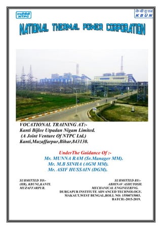
- 1. VOCATIONAL TRAINING AT:- Kanti Bijlee Utpadan Nigam Limited. (A Joint Venture Of NTPC Ltd.) Kanti,Muzaffarpur,Bihar,843130. UnderThe Guidance Of :- Mr. MUNNA RAM (Sr.Manager MM). Mr. M.B SINHA (AGM MM). Mr. ASIF HUSSAIN (DGM). SUBMITTED TO:- SUBMITTED BY:- (HR), KBUNL,KANTI. ABHINAV ASHUTOSH. MUZAFFARPUR. MECHANICAL ENGINEERING. DURGAPUR INSTITUTE ADVANCED TECHNOLOGY. MAKAUT,WEST BENGAL,ROLL NO: 15500715003. BATCH:-2015-2019.
- 2. Vocational Training Report On “Study of Boiler & its Auxiliaries” At NPTC & KBUNL Kanti, Muzaffarpur, Bihar. For the award of the degree BACHELOR OF TECHONOLOGY IN Mechanical Engineering By ABHINAV ASHUTOSH (ME/15/112)&(15500715003) Under The Guidance Of Mr. Munna Ram (Sr. Manager) Mechanical Maintenace Department (KBUNL&NTPC). From: 16 June 2018 to 14 July 2018 Durgapur Institute Of Advanced Technology And Management.(DURGAPUR,W.B,713212).
- 3. Vocational Training Report On “Boiler & Its Auxiliaries” At National Thermal Power Plant, Kanti, Muzaffarpur. Under the guidance of: Mr. MUNNA RAM (Sr. Manager), Mechanical Maintenance Department, NTPC & KBUNL, Muzaffarpur,Bihar,843130. Submitted by: Name:ABHINAV ASHUTOSH. Roll No:ME/15/112&15500715003. College: DIATM DURGAPUR. Duration: 16.06.2018 TO 14.07.2018.
- 5. Certificate This is to certify that this Vocational training Entitled “Study of Boiler and Its Auxiliaries” at NTPC, Muzaffarpur from 16 June 2018 to 14 July 2018 , is a bonafide record presented by Mr. Abhinav Ashutosh Roll no: ME/15/112 Or 15500715003, in fulfilment of Vocational training under B.Tech Curriculum in Mechanical Engineering of Durgapur Institute Of Advanced Technology and Management, Durgapur, West Bengal – 713212. __________________________ Mr. Munna Ram Senior Manager, Mechanical Maintenance Department, NTPC, Muzaffarpur,Bihar,843130. (I)
- 6. ACKNOWLEDGEMENT With profound respect and gratitude, I take opportunity to convey my thanks to Mr. Vakil Ahmad Sir, for permitting me to complete my training in NTPC Ltd. and to be the part of this esteemed organisation. I extend my heartfelt thanks to Mr. Suraj Kumar Santosh Sir, for providing me the proper guidance during my training period. I am extremely grateful to all the operation and guidance that has helped me a lot during the course of training. I have learnt a lot under them and I will always be indebted to them for this value addition in me. At last I would like to convey my thanks to all the members of Mechanical Maintenance Department, and my parents for their cheerful encouragement, unfailing patience and consistent support. Abhinav Ashutosh. Vocational Trainee 16.06.2018 – 14.07.2017 (II)
- 7. Abstract Any thermal power plant is converting the chemical energy of fossil fuel (coal) into electrical energy. The process involved for this conversion is based upon the Modified Rankine Cycle. The major components that are used to accomplish the modified Rankine cycle are: Boiler feed pump, The steam generator water walls (evaporator), Steam generator super heaters, Steam turbine, Reheater, Condenser, Regenerative feed heaters etc. All components of a power generating cycle are vital and critical in operation. In Modified Rankine Cycle, the two most important aspects that is added are reheating & regenerative heating. By reheating we used to send the steam coming from exhaust of the turbines back to the reheater of the boiler so that its enthalpy increases and more work can be done by this steam the other purpose is to make steam dry so that no harm will be done to the blades of the turbine. In NTPC, Kanti, we have three turbines in Tandem coupling namely one H.P Turbine, one I.P Turbine & one L.P Turbine coupled with the generator to which is synchronized with the grid to produce electricity at 50Hz. In all my modesty, I wish to record here that a sincere attempt has been made for the presentation of this project report. I also trust that this study will not only prove to be of academic interest but also will be able to provide an insight into the area of technical management. (III)
- 8. Contents 1. Certificate (I) 2. Acknowledgement (II) 3. Abstract (III) 4. Introduction (1) 5. History of Boiler (2-3) 6. Types of Boiler and its classification (3-7) 7. Basic components of Boiler (8) (i) Economiser (9) (ii) Pre-heater (10) (iii) Super-heater (10) (iv) Re-heater (11) (v) De-super heater (11) (vi) Condenser (12) (vii) Cooling Tower (13) (viii) Fan & Draught system (13) (ix) Ash handling system (14) 8. Thermal Power Plant (i) Block diagram of Thermal power plant (15) (ii) Working principle (16) (iii) Modified Rankine cycle (17) (iv) Process of generation of Electricity (18) (v) Light up process (19) (vi) Component of coal Fired Thermal power station (20-21) 9. Type of Pumps (22) 10. Type of Turbine (23) 12. Important control loop in Thermal power plant (24-26) 13. Unit control desk & panels (27) 14. Advantages & Disadvantages (28) 15. Conclusion (29) 16. References (30)
- 9. Introduction Boiler: A Boiler or steam generator essentially is a container into which water can be fed and steam can be taken out at desired pressure, temperature and flow. For that the boiler should have a facility to burn a fuel and release heat. Thus the function of a boiler can be stated as:- To convert chemical energy of the fuel into heat energy. To transfer this heat energy to water for evaporation as well to steam for superheating. Block diagram of Boiler: (1)
- 10. History of Boiler The steam-generating boiler’s roots go back to the late 1700s and early 1800s with the development of the kettle-type boiler, which simply boiled water into steam. The water was placed above a fire box and then boiled into steam. It wasn’t until around 1867, with the development of the convection boiler that the steam-generating industry began. It may be debated who developed the first steam-generating boiler; however, most will agree that George Babcock and Steven Wilcox were two of the founding fathers of the steam-generating boiler. They were the first to patent their boiler design, which used tubes inside a firebrick- walled structure to generate steam, in 1867, and they formed Babcock & Wilcox Company in New York City in 1891. Their first boilers were quite small, used lump coal, fired by hand, and operated at a very low rate of heat input. The solid firebrick walls that formed the enclosure for the unit were necessary because they helped the combustion process by reradiating heat back into the furnace area. The Stirling Boiler Company, owned by O.C. Barber and named for the street (Stirling Avenue) the facility was on in Barberton, Ohio, also began making boilers in 1891. Their eighth Stirling boiler design was called the H-type boiler (“h” being the eighth letter in the alphabet) and had a brick setting design. The Stirling boiler was much larger than the Babcock & Wilcox boiler and used three drums to help circulate the water and steam flow throughout the boiler. In 1907, the Stirling Boiler Company merged with the Babcock & Wilcox Company. They renamed their boiler the H-type Stirling, and it became one of best-selling boilers of its time, probably because of its ability to produce up to 50,000 pounds of steam per hour. (2)
- 11. However, they were not the only boiler manufacturers during the late 1800s. The Grieve Grate Company and the American Stoker Company were also making boilers of similar all-brick-wall design. They both used a travelling or screw-type grate at the bottom of the boiler to transport the fuel (lump coal) across the inside of the boiler. As the fuel traveled across the inside of the boiler, it was burned and the ash or un-burned fuel would drop into a hopper. These two companies later formed the Combustion Engineering Company in 1912. The new Combustion Engineering Company offered their version of the Grieve and American Stoker boilers and called it the Type E stoker boiler. Types of Boiler and its classifications There are two general types of boilers: ''fire-tube'' and ''water-tube''. Boilers are classified as "high-pressure" or "low-pressure" and "steam boiler" or "hot water boiler." Boilers that operate higher than 15 psig are called "high-pressure" boilers. A hot water boiler, strictly speaking, is not a boiler. It is a fuel-fired hot water heater. Because of its similarities in many ways to a steam boiler, the term ''hot water boiler'' is used. Hot water boilers that have temperatures above 250° Fahrenheit or pressures higher than 160 psig are called ''high temperature hot water boilers''. Hot water boilers that have temperatures not exceeding 250° Fahrenheit or pressures not exceeding 160 psig are called ''low temperature hot water boiler’s. Heating boilers are also classified as to the method of manufacture, i.e., by casting (cast iron boilers) or fabrication (steel boilers). Those that are cast usually use iron, bronze, or brass in their construction. Those that are fabricated use steel, copper, or brass, with steel being the most common material. (3)
- 12. Fire-tube Boilers In fire-tube boilers, combustion gases pass through the inside of the tubes with water surrounding the outside of the tubes. The advantages of a fire-tube boiler are its simple construction and less rigid water treatment requirements. The disadvantages are the excessive weight-per-pound of steam generated, excessive time required to raise steam pressure because of the relatively large volume of water, and inability to respond quickly to load changes, again, due to the large water volume. The most common fire-tube boilers used in facility heating applications are often referred to as ''scotch'' or ''scotch marine'' boilers, as this boiler type was commonly used for marine service because of its compact size (fire-box integral with boiler section). The name "fire-tube" is very descriptive. The fire, or hot flue gases from the burner, is channelled through tubes that are surrounded by the fluid to be heated. The body of the boiler is the pressure vessel and contains the fluid. In most cases, this fluid is water that will be circulated for heating purposes or converted to steam for process use. Fire-tube boilers are: Relatively inexpensive Easy to clean Compact in size Available in sizes from 600,000 btu/hr to 50,000,000 btu/hr Easy to replace tubes Well suited for space heating and industrial process applications Disadvantages of fire-tube boilers include: Not suitable for high pressure applications 250 psig and above Limitation for high capacity steam generation (4)
- 13. Water-tube Boilers In a water-tube boiler, the water is inside the tubes and combustion gases pass around the outside of the tubes. The advantages of a water- tube boiler are a lower unit weight-per-pound of steam generated, less time required to raise steam pressure, a greater flexibility for responding to load changes, and a greater ability to operate at high rates of steam generation. A water-tube design is the exact opposite of a fire-tube. Here, the water flows through the tubes and is encased in a furnace in which the burner fires. These tubes are connected to a steam drum and a mud drum. The water is heated and steam is produced in the upper drum. Large steam users are better suited for the water- tube design. The industrial water-tube boiler typically produces steam or hot water primarily for industrial process applications, and is used less frequently for heating applications. The best gauge of which design to consider can be found in the duty in which the boiler is to perform. Water-tube boilers: Are available in sizes far greater than a fire-tube design , up to several million pounds-per-hour of steam Are able to handle higher pressures up to 5,000 psig Recover faster than their fire-tube cousin Have the ability to reach very high temperatures Disadvantages of the water-tube design include: High initial capital cost Cleaning is more difficult due to the design No commonality between tubes Physical size may be an issue (5)
- 14. Other types of Boiler are: 1. Cast iron boilers. 2. Steam and Condensate boiler system. 3. Hydronic (Hot water) boiler system. Cast Iron Boilers Cast iron boilers are made in three general types: horizontal-sectional, vertical- sectional, and one-piece. Most of the sectional boilers are assembled with push nipples or grommet type seals, but some are assembled with external headers and screw nipples. Horizontal-sectional, cast iron boilers are made up of sections stacked one above the other, like pancakes, and assembled with push nipples. Vertical-sectional, cast iron boilers are made up of sections standing vertically, like slices in a loaf of bread. One-piece cast iron boilers are those in which the pressure vessel is made as a single casting. Steam and Condensate Boiler System Boilers are generally used to provide a source of steam or hot water for facility heating and process needs. In steam and condensate systems, heat is added to water in a boiler causing the water to boil and form steam. The steam is piped to points requiring heat, and as the heat is transferred from the steam to the building area or process requiring heat, the steam condenses to form condensate. In some very low-pressure saturated steam heating applications, the steam distribution piping may be sized to slope back to the boiler so that the steam distribution piping also acts as the condensate return piping (single- pipe system). In other low-pressure applications, there may be steam supply piping and condensate return piping (two-pipe system), although the condensate system is open to the steam system. In typical packaged steam boiler operations, the boiler system may generate steam at about 150 psig for distribution throughout the facility and may be lowered to the operating pressure of equipment supplied through point-of-use pressure reducing stations. As heat is transferred from the steam, condensate is formed which collects in discharge legs until enough condensate is present to operate a trap that isolates the steam distribution system from the condensate system. (6)
- 15. In common facility heating applications, the condensate system is at atmospheric pressure and the system is arranged to drain the condensate to a central condensate receiver, or into local smaller receivers that pump the condensate back to the central condensate receiver. Hydronic Boiler System A boiler is used to heat water that is circulated through a closed loop piping system for general facility and service water heating. Low-temperature systems generally operate below 200° Fahrenheit Medium- temperature systems generally operate at temperatures between 200 and 250° Fahrenheit. A feature of hot water systems' is an expansion tank to accommodate the expansion of the water in the system as the water is heated. The expansion tank, when piped into the system on the suction side of the circulating pumps, also pressurizes the system to prevent flashing in the circulating pump, piping, and piping components. In many low- and medium-pressure systems, pressurization is maintained by flash steam in the expansion tank. In a few hot water systems, pressurization is maintained by maintaining a compressed gas blanket above the water level in the expansion tank. High-temperature hot water systems, which operate above 250° Fahrenheit, are basically the same as hot water systems that operate below 250°F. High-temperature systems are generally installed when a process requires the higher temperature, a number of locations require small quantities of low-pressure steam that the high-temperature hot water can generate in a local converter, or high-temperature drop equipment can be used at end use points to minimize the size of water circulation piping required. Most facility boiler systems are fired using a combustible gas (typically natural gas or propane) or fuel oil. In many facilities, the boilers are designed to fire both a combustible gas fuel and a fuel oil. In these facilities, the combustible gas fuel is generally natural gas that is considered the primary fuel, and fuel oil is considered to be the backup fuel. (7)
- 16. Basic components of Boiler are: Furnace Economiser Air – Preheater Super Heater Re-heater De-Super heater Condenser Cooling tower Fan or draught system Ash handling system Furnace: A boiler furnace is the first pass of the boiler in which the combustible products pass to the super heater and second pass of boiler. The combustion process is a continuous process, which takes place in the first pass of the boiler and control by the fuel input through coal feeders. It is a radiant type and water cooled furnace and enclosure is made up of water wall. The furnace is open at the bottom to allow ash linkers to freely into the furnace bottom ash hopper (through a furnace throat) and at the top of its rear wall, above the arch, to allow hot gases to enter rear gas pass. [Image by: http://wiki.zero-emissions.at] (8)
- 17. Requirement should be satisfied by the furnace: 1. Proper installation, operation and maintenance of fuel burning equipment. 2. Sufficient volume for combustion requirement. 3. Adequate refractoriness and insulation. Economiser: [Image by: Cleanboiler.org] It is located below the LPSH in the boiler and above pre heater. It is there to improve the efficiency of the boiler by extracting heat from flue gases to heat hot water and send it to the boiler drum. Advantages: 1. Fuel economy: It is used to save fuel and increase overall efficiency of the boiler plant. 2. Reducing size of the boiler: A the feed water is preheated in the economiser and enter boiler tube at elevated temperature. The heat transfer area required for evaporation reduced considerably. (9)
- 18. Air-preheater: The heat carried out with the flue gases coming out of economiser are further utilize for preheating the air before supplying to the combustion chamber. It is necessary equipment for supply of hot air for drying the coil in pulverized fuel system to fascinate of fuel in the furnace. [Image by:slideshare.net] Super-heater: [Image by:slideshare.net] The steam generated by the boiler is usually wet or at the most dry saturated because it is in direct contact with water. So, in order to get superheated steam, a device known as super heater has to be incorporated with the boiler. The function of the super-heater system is to accept dry saturated steam from the steam drum and to supply superheated steam at the specific final temperature of 540°C by means of a series of heat transfer surfaces arranged within the boiler gas passes. A super-heater is a surface type heat exchanger generally located in the passage of hot flue gases. The dry saturated steam from the boiler drum flow inside the super-heater tubes and in this way its temperature is increased at same pressure. Types of super-heater: 1. Primary super-heater 2. Secondary super-heater 3. Final super-heater (10)
- 19. Re-heater: Power plant furnaces may have a re-heater section containing tubes heated by hot flue gases outside the tube. External steam from the high pressure turbine is re-routed to go inside the re-heater tube to pick up more energy to go drive intermediate or lower pressure turbines. [Image by: cleanenergysystem.org] De-super heater: [Image by: mechanicalenggineerings.wordpress.net] (A) Super heater – De super heater: The super heater de-super heater is fitted after 10 th coil to control the super heated steam at the specified terminal temperature of 540°C . The maximum design temperature reeduction at the super heater de-super heater is from 446°C to 388°C. (B) Re-heater de-super heater: The re-heater de-super heater is only brought into use when the re-heater outlet temperature rises above the normal temperature. (11)
- 20. Condenser: [Image by: ohio.edu] The condenser condenses the steam from the exhaust of the turbine into the liquid to allow it to be pumped. If the condenser can be made is reduced and efficiency of the cycle increases. Functions: 1. To provide lowest economic heat rejection temp for steam. 2. To convert exhaust steam to water for reserve thus saving on feed water requirement. 3. To introduce make up water. We normally use surface condenser although there is one direct contact condenser as well. In direct type exhaust steam is mixed with directly with De- mineralized cooling water. (12)
- 21. Cooling tower: [Image by: power-en g.com] The cooling towerr is a semi-enclosed device for evaporrative cooling of water by contact with air. The hot water coming out from the condenser is fed to the tower on the top and allowed to tickle on form of the thin sheets or drops. T he air flows from bottom of the tower or perpendicular to the direction of water flow and then exhausts to the atmosphere after effective cooling. The cooling towers are of four types: 1. Natural Draft cooling tower. 2. Forced Draft coooling tower. 3. Induction Draftt cooling tower. 4. Balanced Draft cooling tower. Fan or Draught system: In the boiler, it is essential to supply a controlled amountt of the air to the furnace for effecttive combustion of fuel and to evacuate hot gases formed in the furrnace through the various heat- transfer area of the boiler. This can be done using a chimney or mechanical device such as fans which acts as a pump. (13)
- 22. Ash handling system: The dispersed of ash from a large capacity power station is of same importance as ash is produced in large quantities. Ash handling is a major problem: 1. Manual handling: While barrows as used for this. The ash is collected directly through the ash outlet door from the boiler into the container from manually. 2. Mechanical handling: Mechanical equipment is used for ash disposal, mainly bucket elevator, belt conveyer. Ash generated is 20% in the form of bottom ash and next 80% through flue gases so called fly-ash and collected in ESP. 3. Electrostatics precipitator: From air pre-heater, this flue gases (mixed with ash) goes to ESP. The precipitator has plate blanks (A-F) which are insulated from each other between which the flue gases are made to pass. The dust particles are ionized and attracted by charged electrodes. The electrodes are maintained at 60KV. (14)
- 23. Thermal Power Plant Block Diagram of Thermal Power Plant [Image by: electrical4u.com] (15)
- 24. WORKING PRINCIPLE Coal based thermal power plant works on the principal of Modified Rankin Cycle. Process 1-2 Working fluid is pumped from low to high pressure. Process 2-3 High pressure liquid enters a boiler where it is heated at constant pressure by an external heat source to become a dry saturated vapour. Process 3-4 The dry saturated vapour expands through a turbine, generating power. Process 4-1 The wet vapour then enters a condenser where it is condensed at a constant temperature to become a saturated liquid. Process 3-3’ After the vapour has passed through H.P. it is reheated before passing through I.P. turbine. this prevents the vapour from condensing during its expansion which can seriously damage the turbine blades, and improves the efficiency of the cycle [Image by: en.wikipedia.org] (16)
- 25. Modified Rankine cycle means reheat rankine cycle or regenerative rankine cycle. The efficiency of modified Rankine cycle is improved. Reheat rankine cycle means after the steam expanded from turbine again the steam is reheated and sent to another turbine for expansion. The remaining cycle is similar to normal rankine cycle. Regenerative rankine cycle means, a small quantity of mass of steam is extracted from turbine and is sent to feed water heater which is placed in between pump and condenser in order to heat the water before entering the boiler. The remaining cycle is same as normal rankine cycle. [Image by: en.wikipedia.org] (17)
- 26. PROCESS OF GEN ERATION OF ELECTRICITY NTPC, Kanti is a Thermal Power Plant. The functioning of every thermal power plant is based on the following processes: - 1. Coal to Steam. 2. Steam to Mechanical Power 3. Power Generation, Transmission & Distribution. STEP-1 Coal To Steam Coal and Water are prrimary inputs to a thermal power plant. This process of conversion of water to steam by using the heat energy produced by burning coal for producing heat takes place in the boiler And its auxiliaries. Coal burns in a furnace located at the bottom part of the boiler. Feed water is supplied to the b oiler drum by boiler Feed pumps, where w ater is heated and converted into saturated steam This is further superhe ated in the super heaters. [Image by: poweer.eng.com] STEP-2 Steam To Mechan ical Power This is the most important process of a power plant. The superheated Steam produced in the boiler at high pressure and temperature is feed to the turbine. The steam expands in the turbine giving up heat energy, which is transformed into mechanical energy on turbine shaft. Thus, Mechanical power is obtained from the turbine shaft. STEP-3 Power Generation , transmission & Distribution Mechanical power produced at the shaft of the turbine is used to Rotate the rotor of an electrical generator that produces electric power. The electric power produced by the generator is boosted to a higher voltage by a generator transformer to reduce the transmission losses. This power at EHV i.e. 400 kV is transmitted and distributed by EHV transmission lines. (18)
- 27. LIGHT UP PROCESS STEP-1 A controlled quantity of crushed coal is fed to each bowl mill (pulveriser) by its respective feeders and primary air is supplied from the primary air fans which drives the coal as it is being pulverized and transports the pulverized coal through the coal piping system to the coal burner. STEP-2 The pulverized coal and air discharge from the coal burners is directed towards the centre of furnace to form fire ball. STEP-3 The secondary air heating system supplies secondary air for combustion in the furnace around the pulverized coal burners and through auxiliary air compartments, directly adjacent to the coal burner compartments. STEP-4 Above a predictable minimum loading condition, the ignition becomes self-sustaining. Combustion is completed as the gases spiral up in the furnace. (19)
- 28. Components of Coal Fired Thermal Power Station: Coal Preparation Fuel preparation system: In coal-fired power stations, the raw feed coal from the coal storage area is first crushed into small pieces and then conveyed to the coal feed hoppers at the boilers. The coal is next pulverized into a very fine powder, so that coal will undergo complete combustion during combustion process. Pulverizer: is a mechanical device for the grinding of many different types of materials. For example they are used to pulverize coal for combustion in the steam-generating furnaces of fossil fuel power plants. There are six mills located adjacent to the furnace at 0 m level .These mills pulverize coal to desired fineness to be fed to the furnace for combustion. The main structure of the pulverisering mill is fabricated from mild steel in three cylindrical sections, the bottom section (the mill housing support )which support the entire unit and encloses the mill drive gear unit, a center section (the mill housing)that contains the rotary grinding element and upper section (the classifier housing )comprising an accommodate the gas loading cylinders of the mill loading gear .A platform around the upper section provide an access to an inspection door and to the top of the mill routine maintenance and is served by detachable ladder . The grinding element comprises of 3 rotatory rollers. Types of Pulverisers: Ball and Tube mills Ring and Ball mills MPS; Ball mill Demolition Dryers: They are used in order to remove the excess moisture from coal mainly wetted during transport. As the presence of moisture will result in fall in efficiency due to incomplete combustion and also result in CO emission. Magnetic separators: Coal which is brought may contain iron particles. These iron particles may result in wear and tear. The iron particles may include bolts, nuts wire fish plates etc. so these are unwanted and so are removed with the help of magnetic separators. The coal we finally get after these above process are transferred to the storage site. Purpose of fuel storage is two – Fuel storage is insurance from failure of normal operating supplies to arrive. (20)
- 29. Storage permits some choice of the date of purchase, allowing the purchaser to take advantage of seasonal market conditions. Storage of coal is primarily a matter of protection against the coal strikes, failure of the transportation system & general coal shortages. There are two types of storage: Live Storage (boiler room storage): storage from which coal may be withdrawn to supply combustion equipment with little or no remanding is live storage. This storage consists of about 24 to 30 hrs. of coal requirements of the plant and is usually a covered storage in the plant near the boiler furnace. The live storage can be provided with bunkers & coal bins. Bunkers are enough capacity to store the requisite of coal. From bunkers coal is transferred to the boiler grates. Dead storage- stored for future use. Mainly it is for longer period of time, and it is also mandatory to keep a backup of fuel for specified amount of days depending on the reputation of the company and its connectivity. There are many forms of storage some of which are – 1. Stacking the coal in heaps over available open ground areas. 2. As in (I). But placed under cover or alternatively in bunkers. 3. Allocating special areas & surrounding these with high reinforced concerted retaking walls. (21)
- 30. TYPES OF PUMP Condensate Extraction Pump (CEP) : The function of Condensate extraction pumps is to pump out the condensate to the desecrator through, LP heaters. The steam from the LP cylinders exhausts into the condenser shells where it is constrained to flow across the water tubes, through which cooling water is circulated. There are two 100% duty extraction pumps, one remains in duty and one remains stand by. The thrust bearings in the driving motors have temperatures sensor, which can trip the motors automatically. The pump discharge the condensate to the LP heater system with a pressure increased to approx. 18 kg/sq. cm from 70-75 mm of Hg. Air Extraction Pump (AEP): The function of the air extraction pump is to raise and maintain the vacuum conditions in the turbine main condensers, and to remove air and other non-condensable gases vented to the condenser from various parts of the turbine and feed water heating system. Boiler Feed Pump (BFP): Boiler feed pump is the most critical component of a power plant. It is a rotary machine, which is coupled to a motor through variable speed coupling or turbo coupling. Feed water supplied to the boiler drum should have high pressure which is achieved when passed through boiler feed pump. Whenever the pressure of water is to be raised, BFP is used. The discharge pressure of a boiler feed pump is approx. 150 kg/sq. cm. [Image by: mechanicalengineerings.wordpress.com] (22)
- 31. TYPES OF TURBINE High pressure turbine It is of single flow design with eight stages of blading. Each stage has moving and stationary blades. Superheated steam (at 1100⁰c) from boiler drum enters in to it. Speed-3000rpm Intermediate pressure turbine Double flow design with seven stages of blading on either side. Each stage has moving and stationary blades. Reheated steam (at 535⁰ c) from H.P turbine outlet enters in to it. Speed-3000rpm Low pressure turbine It is also of double flow design with 6 stages in front and rear flow paths. Each stage has moving and stationary blades. Stem out of I.P. turbine directly enters in to it. Speed-3000rpm [Image by: slideshare.in] (23)
- 32. IMPORTANT CONTROL LOOPS IN A THERMAL POWER PLANT Basic Block Diagram Of Any Closed Control Loop : [Image by: en.wikipedia.org] Process: The equipment whose present level, pressure and other values is to be measured is known as process. Set Point: The required value of parameter is set by the manual which is to be maintained in order to protect the process from damage. Measurement: The present value of parameter in process is measured here. Generally, capacitance type of measurement is used. Two tapping from the process, one at high pressure & other at low pressure, is taken and transmitted through isolating diaphragm and silicon oil fill fluid to a sensing diaphragm in the centre of the differential pressure cell. The sensing diaphragm deflects in response to differential pressure. The position of the sensing diaphragm is deflected by capacitor plates on both sides of the sensing diaphragm. The differential capacitor between the sensing diaphragm and the capacitor plate is converted electronically to a 4-20 mA signal and transmitted to comparator. This measurement sometimes also known as transmitter. (24)
- 33. Comparator: It compares the signal between set point and measured value. If the two values differ from one another, an error signal is generated and sent to the controller. Controller: It is an electronic card which, according to the error signal sent by comparator, gives a current signal between 4-20 mA to final control element. Final Control Element: It is that portion of the loop which directly changes the value of the manipulated process variable and finally do some work to maintain the set point of the process. Drum Level Control: The required drum level is set at the set point. The present drum level is then measured which is done by capacitor type transmitter. Two tapping, one at the bottom in water while other at the top in steam, is made and allowed to flow to the transmitter. Since, the two elements are in different states, steam is condensed and collected in a constant head unit (CHU) before going to the transmitter where the present drum level is measured and converted to current signal between 4-20 mA. This set value and measured value are then compared in a comparator and an error signal, if any, is generated and sent to controller which finally directs the final control element to control the drum level. Here, the final control element is a control valve through which a fluid passes that adjusts the size of the flow passage as directed by a signal from controller to modify the rate of flow of the fluid. Hence, the drum level is controlled. (25)
- 34. D.P. Across Feed Control Station: [Image by: idc-online.com/slideshare] In order to maintain the linear characteristics of the feed regulating valves under different loads, the differential pressure (D.P.) control loops maintains a fixed differential across the regulating valves and BFP discharge pressure is varied by changing BFP motor speed through hydraulic scoop tube device which is the final control element here. The D.P. across feed station (comparator) is sensed and is fed to the controller. The controller are automatically adjusted as function of steam flow to achieve stable condition. The reserve Boiler Feed pump scoop tube automatically follows the running pump scoop tube and the change over to the reserve BFP takes place with the scoop tube in the same position of the scoop tube. Combustion Control : The combustion control proposed for this boiler comprises of the following loops: a. Master pressure control b. Pulverized coal flow control c. Combustion air flow control d. Oxygen trim control e. Mill temperature and air flow control (26)
- 35. UNIT CONTROL DESK & PANELS The operation of each unit is envisaged from the central unit control room. It is located in the control bay at 9.0m TG floor. It is adequately illuminated and is centrally air conditioned. For operational convenience, the control room front wall has complete glass paneling for TG hall view and the two double doors for entry from TG hall. The control board has a special profile with three sloping surfaces for mounting a large fascias, instruments and controls. The automatic control station and drive control switches & Indications are located on the first sloping surface. The process indicators/recorders and ammeters are mounted on the second sloping surface and the alarm annunciation window fascias are mounted on the top i.e. third sloping surface. The unit control boards are arranged in logical operating sequence from the left to right starting with Air & Flue Gas Fuel oil Bowl Mills Steam & Feed water Regenerative System Turbine Generator (27)
- 36. ADVANTAGES OF COAL BASED THERMAL POWER PLANT They can respond to rapidly changing loads without difficulty A portion of the steam generated can be used as a process steam in different industries Steam engines and turbines can work under 25 % of overload continuously Fuel used is cheaper Cheaper in production cost in comparison with that of diesel power stations. DISADVANTAGES OF COAL BASED THERMAL POWER PLANT Maintenance and operating costs are high Long time required for erection and putting into action A large quantity of water is required Great difficulty experienced in coal handling Presence of troubles due to smoke and heat in the plant Unavailability of good quality coal Maximum of heat energy lost Problem of ash removing (28)
- 37. Conclusion Industrial training being an integral part of engineering curriculum provides not only easier understanding but also aspect of all things which differ considering from theoretical models. During my training, I gained a lot of practical knowledge which otherwise could have been exclusive to me. The practical exposure required here will pay rich dividends to me when I will set my foot as an engineer. The training at NTPC, Kanti was altogether an exotic experience, since work, culture and mutual co-operation was excellent here. Moreover fruitful result of adherence to quality control, awareness of safety and employees were fare which is much evident here. (29)
- 38. References Modern power station practice-Volume B & Volume C. Power plant engineering- by PK Nag. Control and Instrumentation Operation & Maintenance Manual (MTPS) – Volume H. www.ntpc.co.in http://indianpowersector.com/home/powerstation/thermal-power-plant/ https://en.wikipedia.org/wiki/Boiler https://en.wikipedia.org/wiki/Thermal_power_station https://en.wikipedia.org/wiki/Rankine_cycle nptel.ac.in/courses/112106133/Module_5/2_Rankinecycle.pdf en.wikipedia.org www.mechanicalengineerings.wordpress.com www.electrical4u.com (30)
- 39. SPECIAL THANKS TO:- KBUNL & NTPC KANTI,MUZAFFARPUR,BIHAR,843130. MR. MUNNA RAM (SR. MANAGER MM). MR. M.B SINHA (AGM MM). MR. ASIF HUSSAIN (DGM). MR. PANNA LAL PRAJAPATI. ( 31)