Downloaded 132 times


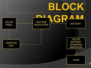
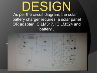
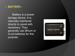
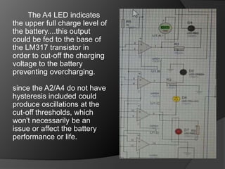


The document outlines a solar battery charger mini project developed by Swedel Dsouza and Jenifer Nadar, focusing on harnessing solar energy to charge a 6V battery that powers LED lights and mobile phone chargers. It describes the components used, including solar panels, voltage regulators, and indicators for battery status, emphasizing advantages such as preventing overcharging and being environmentally friendly. Applications include providing emergency power, usage in remote areas, and everyday convenience, highlighting the potential for sustainable energy solutions.