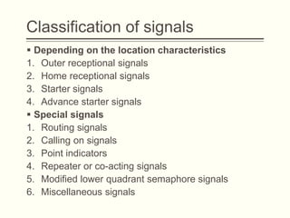
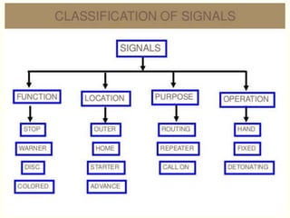
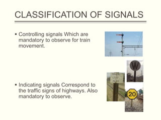
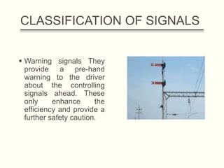
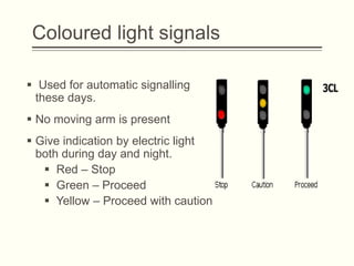
Gujarat Power Eng.& Research Institute ,
Mewad , Mehsana.
By : Prof. Sadanand Sahu.
DEPARTMENT OF CIVIL ENGINEERING
RAILWAY, BRIDGE AND TUNNELS
Railway : Signalling & Interlocking
Introduction
 Signaling is the device by which the movement of
trains is controlled.
 Highly important in terms of safety.
 Trains can be operated efficiently, utilization of tracks
and tracks can be done at maximum levels.
 Signaling includes signals, points, blocks and other
equipment;
Objects of Signalling
 Maintain safe distance between trains running in the same
direction on a single line.
 Safe distance between trains which are approaching or crossing
a crossing.
 To run the trains at restricted speeds during repair works.
 At junctions to prevent the trains from colliding .
 At the diverging tracks to give indication about the direction to
move.
 In marshalling yards, to provide safety against shunting.
 To provide facilities for the maximum use of track and rolling
stock.
 Increase the safety
Classification of signals
 Depending on the operational characteristics.
1. Fog or audible or detonating signals.
2. Visual indication hand signals.
3. Visual indication fixed signals.
 Depending on the functional characteristics
1. Stop or semaphore type signals
2. Warner signals
3. Shunting signals
4. Coloured light signals
Classification of signals
 Depending on the location characteristics
1. Outer receptional signals
2. Home receptional signals
3. Starter signals
4. Advance starter signals
 Special signals
1. Routing signals
2. Calling on signals
3. Point indicators
4. Repeater or co-acting signals
5. Modified lower quadrant semaphore signals
6. Miscellaneous signals
CLASSIFICATION OF SIGNALS
 Controlling signals Which are
mandatory to observe for train
movement.
 Indicating signals Correspond to
the traffic signs of highways. Also
mandatory to observe.
CLASSIFICATION OF SIGNALS
 Warning signals They
provide a pre-hand
warning to the driver
about the controlling
signals ahead. These
only enhance the
efficiency and provide a
further safety caution.
Detonating Signals
 Used when hand and fixed signals or not visible
(foggy and cloudy conditions)
 Also used during emergencies (derailment, accidents
etc.,)
 These are in the form of detonators fixed on the top
of rails
 When engine passes over it explodes with big sound
and alerts the driver to stop the train.
 3 to 4 detonators are placed at an interval of about
10 to 15m at 400 to 500m ahead.
Hand Signals
 Given by the guard using coloured flags or by bare
arms
 During night times kerosene lamps fitted with
movable green, red and yellow coloured glasses are
used.
• Green – proceed
• Red - dead stop
• Yellow – proceed with caution
Semaphore Signals
 Consist of a vertical post on which a movable arm is
pivoted at the top.
 Arm can be kept horizontal or it can be inclined at 45
degree to horizontal
 Outer end of arm is 2.45cm broader than that at post.
 Movable arm is controlled by means of levers and
cables from the cabin.
 Spectacles of red and green or fixed in the arm
Semaphore Signals
 Horizontal arm indicates “
DANGER –STOP ” and
the inclined arm indicates
“ CLEAR – PROCEED”.
 In the day time position
of arm indicates the
signal.
 During the night time light
of lamp passing through
spectacle gives the
signal.
Warner Signal
 This is similar to semaphore signal
 Difference is it contains a fish tailed arm
 These signals are placed ahead the semaphore
signals to warn the driver before entering the railway
station.
 When the arm is horizontal – indicates signal ahead
is stop
 Warner signals are placed 540m away from the first
stop signal.
Warner Signal
 Some times warner signals are provided with yellow
lights instead of red to distinguish them from
semaphore signals during nights.
 Some times both warner and semaphore signals are
placed on the same pole
 Both horizontal – stop line not clear
 Semaphore lower, warner horizontal – proceed with
caution
 Both lowered – proceed on with confidence
Warner Signal
Coloured light signals
 Used for automatic signalling
these days.
 No moving arm is present
 Give indication by electric light
both during day and night.
 Red – Stop
 Green – Proceed
 Yellow – Proceed with caution
Signalling Systems
 Absolute block system
 Space interval system
 Time interval system
 Pilot guard system
Absolute Block System
 This system involves dividing the entire length of the
track into sections called block sections.
 A block section lies between two stations that are
provided with block instruments
 The block instruments of adjoining stations are
connected through railway lines.
 A token can be taken from the block instrument of a
particular station with the consent of both the station
masters.
Absolute Block System
 In the absolute block system, the departure of a train
from one station to another is not permitted until and
unless the previous train has completely arrived at
the next station.
 i.e., trains are not permitted to enter the section
between two stations at the same time.
 Each station has two block instruments;
 one for the station ahead and the other for the
previous station
 These are electrically interconnected
Time interval method
 Trains are Spaced Over an length of a track in such a
way that , if the first train stops, the following train
driver should be able to stop the train in sufficient
distance without colliding with the first one.
 This type is used where traffic is less and weight of
the trains are less, e.g: Trams
 This Type of System cannot be used in Passenger
rails since weight and traffic is High.
Space interval method
 In this method of “Control Over Movement”, the
length of the track is divided in to sections called
Blocks.
 The Entry of a train in to the ‘Block’ is controlled in
such a way that only when it is free, a train can be
allowed to enter it.
 This means that between two consecutive trains ,
there is definite space interval
Interlocking
 An interlocking is an arrangement of signal apparatus
that prevents conflicting movements through an
arrangement of tracks such as junctions or crossings.
 Interlocking system used mechanical device both to
operated the signaling device and ensure their safe
operation.
 Electrical relay interlocking were used.
Type of interlocking
1. RRI means the station is interlocked and worked
with control panel located in RRI office.
2. Control panel has a geometrical layout of the entire
yard controlled by route interlocking.
3. Indication Panel is the points setting of the route
approach locking and provides in front of the
SM(panel).
Type of interlocking
4.Points which is yard expect hand operated points
are power operated and worked from the RRI cabin.
5.Crank Handle Interlocking is the yard of the point
machine has been group into various group . One
crank handle of a one group can not be use on the
point machine of another group.
6.Track Circuit on the indication panel are mark in
different color and are provide with indication lamp.
Essentials
 It should not be possible to turn a signal off unless all
points for the line on which the train is to be received
are correctly set, all the facing points are locked, and
all interlocked level crossings are closed and
inaccessible to road traffic.
 The line should be fully isolated before the signal is
turned off, i.e., no loose wagons should be able to
enter this line.
 After the signal has been turned off, it should not be
possible to make adjustments in the points or locks
on the route.
Essentials
 It should not be possible to turn any two signals off at
the same time, as this can lead to conflicting
movements of the trains.
 Wherever feasible, the points should be so
interlocked as to avoid any conflicting movement.
standards
 1st standard
 makes use of key interlocking.
 Running speed for trains restricted to 50kmph
 2nd standard:
 used on non trunk main routes
 Operated mechanically or electrically
 Speed less than 75kmph
 3rd standard;
 Makes used of mechanically or electrically interconnected
 Uses latest interlocking techniques also.
Key Interlocking
 Simplest method of interlocking
 Involves the manipulation of keys in one form or other
 This type of interlocking is normally provided with
standard 1 interlocking
 Arrangement of key interlocking is done as below
when a main line and branch line exist on a single
track.
 Point can be set either for main line or branch line
 A, B are the keys for main and branch lines. At any
point only one of the keys can be taken out.
Key Interlocking
 Lever frame operating the signals is provided with 2
signals and will be operated by keys A and B only.
 If the train is to be received on main line, the key is
locked for point on main line, and A is taken out and
inserted in the lever for signal of main line.
 Thus lowering the signal of main line.
 This type of signal is called indirect interlocking.
 If there are multiple lines succession interlocking will
be used.
Mechanical interlocking
 In mechanical interlocking plants, a locking bed is
constructed, consisting of steel bars forming a grid.
The levers that operate switches, derails, signals or
other appliances are connected to the bars running in
one direction.
 The bars are constructed so that if the function
controlled by a given lever conflicts with that
controlled by another lever, mechanical interference
is set up in the cross locking between the two bars, in
turn preventing the conflicting lever movement from
being made.
Mechanical interlocking
 In purely mechanical plants, the
levers operate the field devices,
such as signals, directly via a
mechanical rodding or wire
connection.
 The levers are about shoulder
height since they must supply a
mechanical advantage for the
operator.
 Cross locking of levers was effected
such that the extra leverage could
not defeat the locking
Different cases of mechanical
interlocking
 Normal interlocking:
 Pulling one lever locks other lever in normal position
 Back locking or release locking:
 Lever in normal position locks the other lever in normal
position.
 When pulled other lever released and is free to operate
 When other pulled, first one gets locked in pulled position.
 Both wall locking:
 Once the lever is locked other lever locked in current
position.
 Conditional locking:
 Pulling one lever is locks other lever only when cetain.
Electrical interlocking
 Achieved through electrical switches known as relays
 Manipulation of relays achieves interlocking
 In the place of plungers or in addition to plungers, lever locks
are attached with levers.
 These work by making use of the principle of electromagnetism.
 Soft iron core wrapped inside a iron core turns into magnet
when current passes through it.
 An arrangement named armature is attached to this magnet.
 Depending on whether the armature is attached or not
interlocking works here.
 This entire system is housed in a glass or metal box
Panel interlocking
 All points and signals are operated electrically from a
central location
 The switches for operating these points and signals
are mounted on a panel, which also bears the
diagram of the yard layout
 Electrical interlocking is achieved by means of relays
 Centralized controlling of greater area is great
advantage
 With elimination of inter cabin controlling greater
number of trains can be run with less
Route Relay Interlocking
 Improvement over panel interlocking
 In panel interlocking each point in the line has to be
individually setup with a switch and clearance of
signal is obtained by operating the switch.
 In R.R.I only a pair of switches are used for doing all
these operations automatically.
 Signal is also cleared in the similar automated
manner The main requirement for this type of
interlocking is entire track needs to be track circuited.
Route Relay Interlocking
 The conditions of track circuit and various indications
of all signal are mirrored on the panel that carries the
diagram of the yard.
 By looking at these indications a panel operator can
a panel operator can easily know whether a track is
free or not.
 Once the route is set to allow, the portion gets
illuminated with white light.
 If the route is occupied, it will show in red colour.
 If the train has cleared the track, the lights will off.
Railway_signalling and interlocking_.pptx

Railway_signalling and interlocking_.pptx

  • 1.
    Gujarat Power Eng.&Research Institute , Mewad , Mehsana. By : Prof. Sadanand Sahu. DEPARTMENT OF CIVIL ENGINEERING RAILWAY, BRIDGE AND TUNNELS Railway : Signalling & Interlocking
  • 2.
    Introduction  Signaling isthe device by which the movement of trains is controlled.  Highly important in terms of safety.  Trains can be operated efficiently, utilization of tracks and tracks can be done at maximum levels.  Signaling includes signals, points, blocks and other equipment;
  • 3.
    Objects of Signalling Maintain safe distance between trains running in the same direction on a single line.  Safe distance between trains which are approaching or crossing a crossing.  To run the trains at restricted speeds during repair works.  At junctions to prevent the trains from colliding .  At the diverging tracks to give indication about the direction to move.  In marshalling yards, to provide safety against shunting.  To provide facilities for the maximum use of track and rolling stock.  Increase the safety
  • 4.
    Classification of signals Depending on the operational characteristics. 1. Fog or audible or detonating signals. 2. Visual indication hand signals. 3. Visual indication fixed signals.  Depending on the functional characteristics 1. Stop or semaphore type signals 2. Warner signals 3. Shunting signals 4. Coloured light signals
  • 5.
    Classification of signals Depending on the location characteristics 1. Outer receptional signals 2. Home receptional signals 3. Starter signals 4. Advance starter signals  Special signals 1. Routing signals 2. Calling on signals 3. Point indicators 4. Repeater or co-acting signals 5. Modified lower quadrant semaphore signals 6. Miscellaneous signals
  • 7.
    CLASSIFICATION OF SIGNALS Controlling signals Which are mandatory to observe for train movement.  Indicating signals Correspond to the traffic signs of highways. Also mandatory to observe.
  • 8.
    CLASSIFICATION OF SIGNALS Warning signals They provide a pre-hand warning to the driver about the controlling signals ahead. These only enhance the efficiency and provide a further safety caution.
  • 9.
    Detonating Signals  Usedwhen hand and fixed signals or not visible (foggy and cloudy conditions)  Also used during emergencies (derailment, accidents etc.,)  These are in the form of detonators fixed on the top of rails  When engine passes over it explodes with big sound and alerts the driver to stop the train.  3 to 4 detonators are placed at an interval of about 10 to 15m at 400 to 500m ahead.
  • 10.
    Hand Signals  Givenby the guard using coloured flags or by bare arms  During night times kerosene lamps fitted with movable green, red and yellow coloured glasses are used. • Green – proceed • Red - dead stop • Yellow – proceed with caution
  • 11.
    Semaphore Signals  Consistof a vertical post on which a movable arm is pivoted at the top.  Arm can be kept horizontal or it can be inclined at 45 degree to horizontal  Outer end of arm is 2.45cm broader than that at post.  Movable arm is controlled by means of levers and cables from the cabin.  Spectacles of red and green or fixed in the arm
  • 12.
    Semaphore Signals  Horizontalarm indicates “ DANGER –STOP ” and the inclined arm indicates “ CLEAR – PROCEED”.  In the day time position of arm indicates the signal.  During the night time light of lamp passing through spectacle gives the signal.
  • 13.
    Warner Signal  Thisis similar to semaphore signal  Difference is it contains a fish tailed arm  These signals are placed ahead the semaphore signals to warn the driver before entering the railway station.  When the arm is horizontal – indicates signal ahead is stop  Warner signals are placed 540m away from the first stop signal.
  • 14.
    Warner Signal  Sometimes warner signals are provided with yellow lights instead of red to distinguish them from semaphore signals during nights.  Some times both warner and semaphore signals are placed on the same pole  Both horizontal – stop line not clear  Semaphore lower, warner horizontal – proceed with caution  Both lowered – proceed on with confidence
  • 15.
  • 16.
    Coloured light signals Used for automatic signalling these days.  No moving arm is present  Give indication by electric light both during day and night.  Red – Stop  Green – Proceed  Yellow – Proceed with caution
  • 17.
    Signalling Systems  Absoluteblock system  Space interval system  Time interval system  Pilot guard system
  • 18.
    Absolute Block System This system involves dividing the entire length of the track into sections called block sections.  A block section lies between two stations that are provided with block instruments  The block instruments of adjoining stations are connected through railway lines.  A token can be taken from the block instrument of a particular station with the consent of both the station masters.
  • 19.
    Absolute Block System In the absolute block system, the departure of a train from one station to another is not permitted until and unless the previous train has completely arrived at the next station.  i.e., trains are not permitted to enter the section between two stations at the same time.  Each station has two block instruments;  one for the station ahead and the other for the previous station  These are electrically interconnected
  • 20.
    Time interval method Trains are Spaced Over an length of a track in such a way that , if the first train stops, the following train driver should be able to stop the train in sufficient distance without colliding with the first one.  This type is used where traffic is less and weight of the trains are less, e.g: Trams  This Type of System cannot be used in Passenger rails since weight and traffic is High.
  • 21.
    Space interval method In this method of “Control Over Movement”, the length of the track is divided in to sections called Blocks.  The Entry of a train in to the ‘Block’ is controlled in such a way that only when it is free, a train can be allowed to enter it.  This means that between two consecutive trains , there is definite space interval
  • 22.
    Interlocking  An interlockingis an arrangement of signal apparatus that prevents conflicting movements through an arrangement of tracks such as junctions or crossings.  Interlocking system used mechanical device both to operated the signaling device and ensure their safe operation.  Electrical relay interlocking were used.
  • 23.
    Type of interlocking 1.RRI means the station is interlocked and worked with control panel located in RRI office. 2. Control panel has a geometrical layout of the entire yard controlled by route interlocking. 3. Indication Panel is the points setting of the route approach locking and provides in front of the SM(panel).
  • 24.
    Type of interlocking 4.Pointswhich is yard expect hand operated points are power operated and worked from the RRI cabin. 5.Crank Handle Interlocking is the yard of the point machine has been group into various group . One crank handle of a one group can not be use on the point machine of another group. 6.Track Circuit on the indication panel are mark in different color and are provide with indication lamp.
  • 25.
    Essentials  It shouldnot be possible to turn a signal off unless all points for the line on which the train is to be received are correctly set, all the facing points are locked, and all interlocked level crossings are closed and inaccessible to road traffic.  The line should be fully isolated before the signal is turned off, i.e., no loose wagons should be able to enter this line.  After the signal has been turned off, it should not be possible to make adjustments in the points or locks on the route.
  • 26.
    Essentials  It shouldnot be possible to turn any two signals off at the same time, as this can lead to conflicting movements of the trains.  Wherever feasible, the points should be so interlocked as to avoid any conflicting movement.
  • 27.
    standards  1st standard makes use of key interlocking.  Running speed for trains restricted to 50kmph  2nd standard:  used on non trunk main routes  Operated mechanically or electrically  Speed less than 75kmph  3rd standard;  Makes used of mechanically or electrically interconnected  Uses latest interlocking techniques also.
  • 28.
    Key Interlocking  Simplestmethod of interlocking  Involves the manipulation of keys in one form or other  This type of interlocking is normally provided with standard 1 interlocking  Arrangement of key interlocking is done as below when a main line and branch line exist on a single track.  Point can be set either for main line or branch line  A, B are the keys for main and branch lines. At any point only one of the keys can be taken out.
  • 29.
    Key Interlocking  Leverframe operating the signals is provided with 2 signals and will be operated by keys A and B only.  If the train is to be received on main line, the key is locked for point on main line, and A is taken out and inserted in the lever for signal of main line.  Thus lowering the signal of main line.  This type of signal is called indirect interlocking.  If there are multiple lines succession interlocking will be used.
  • 30.
    Mechanical interlocking  Inmechanical interlocking plants, a locking bed is constructed, consisting of steel bars forming a grid. The levers that operate switches, derails, signals or other appliances are connected to the bars running in one direction.  The bars are constructed so that if the function controlled by a given lever conflicts with that controlled by another lever, mechanical interference is set up in the cross locking between the two bars, in turn preventing the conflicting lever movement from being made.
  • 31.
    Mechanical interlocking  Inpurely mechanical plants, the levers operate the field devices, such as signals, directly via a mechanical rodding or wire connection.  The levers are about shoulder height since they must supply a mechanical advantage for the operator.  Cross locking of levers was effected such that the extra leverage could not defeat the locking
  • 32.
    Different cases ofmechanical interlocking  Normal interlocking:  Pulling one lever locks other lever in normal position  Back locking or release locking:  Lever in normal position locks the other lever in normal position.  When pulled other lever released and is free to operate  When other pulled, first one gets locked in pulled position.  Both wall locking:  Once the lever is locked other lever locked in current position.  Conditional locking:  Pulling one lever is locks other lever only when cetain.
  • 33.
    Electrical interlocking  Achievedthrough electrical switches known as relays  Manipulation of relays achieves interlocking  In the place of plungers or in addition to plungers, lever locks are attached with levers.  These work by making use of the principle of electromagnetism.  Soft iron core wrapped inside a iron core turns into magnet when current passes through it.  An arrangement named armature is attached to this magnet.  Depending on whether the armature is attached or not interlocking works here.  This entire system is housed in a glass or metal box
  • 34.
    Panel interlocking  Allpoints and signals are operated electrically from a central location  The switches for operating these points and signals are mounted on a panel, which also bears the diagram of the yard layout  Electrical interlocking is achieved by means of relays  Centralized controlling of greater area is great advantage  With elimination of inter cabin controlling greater number of trains can be run with less
  • 35.
    Route Relay Interlocking Improvement over panel interlocking  In panel interlocking each point in the line has to be individually setup with a switch and clearance of signal is obtained by operating the switch.  In R.R.I only a pair of switches are used for doing all these operations automatically.  Signal is also cleared in the similar automated manner The main requirement for this type of interlocking is entire track needs to be track circuited.
  • 36.
    Route Relay Interlocking The conditions of track circuit and various indications of all signal are mirrored on the panel that carries the diagram of the yard.  By looking at these indications a panel operator can a panel operator can easily know whether a track is free or not.  Once the route is set to allow, the portion gets illuminated with white light.  If the route is occupied, it will show in red colour.  If the train has cleared the track, the lights will off.