Download as PDF, PPTX

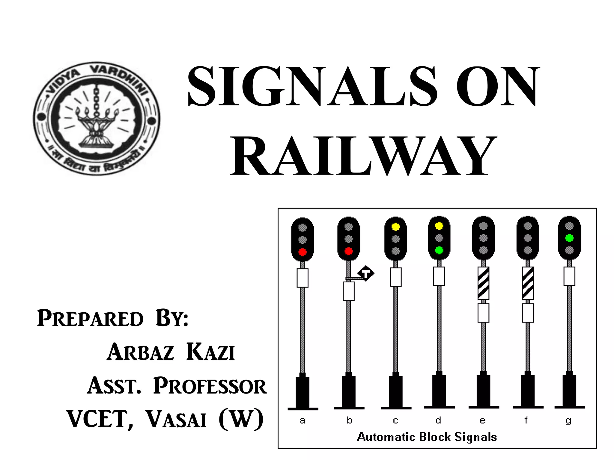
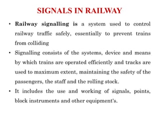
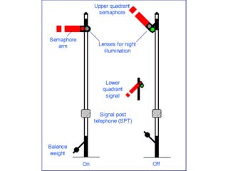
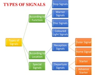

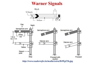

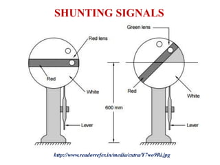
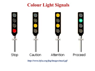
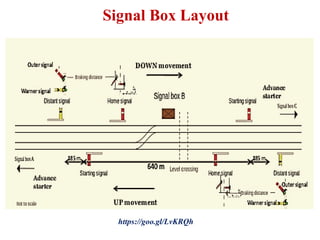

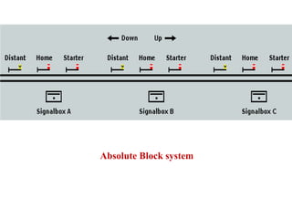
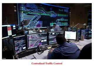


The document provides information about railway signalling systems. It discusses the objectives of signalling such as ensuring safety between trains and maximizing track utility. It describes different types of signals according to function and location like stop signals, warner signals, and home signals. The types and purpose of various signalling equipment are explained, including semaphore signals, disc signals, colour light signals, and calling-on signals. The document also covers signalling methods like absolute block system and centralized traffic control to regulate train movements. Interlocking systems that prevent conflicting train movements at junctions are also summarized.