i
RATMALANA
UNIVERSITY COLLEGE OF
ULTRASONICRADAR SYSTEM
Submitted by:
K.G.S.Prasanna (RT/TCT/21/21)
Supervisor:
Ms.Chathurika Pathmakulasooriya
Division of Telecommunication
Technology University College of
Ratmalana
2.
i
Acknowledgement
I would liketo express my heartfelt gratitude to Ms. Chathurika Padmakulashuuriya, my
supervisor, for her continuous support, valuable guidance, and encouragement throughout the
development of my project, Ultrasonic Radar System. Her expertise and insightful suggestions
played a crucial role in shaping this project, and I truly appreciate her patience and dedication in
helping me achieve my goals.
I am also deeply thankful to my lecturers and institution for providing me with the necessary
knowledge and resources to complete this project successfully. Their teachings have been
instrumental in enhancing my technical and problem-solving skills.
Additionally, I would like to extend my appreciation to my friends and fellow students for their
support, valuable discussions, and motivation throughout this journey. Their input and
encouragement helped me stay focused and overcome challenges.
Lastly, I am extremely grateful to my family for their unwavering support, patience, and belief in
me. Their encouragement has always been a driving force behind my success.
This project has been a great learning experience, allowing me to explore new concepts and
enhance my technical skills. I am truly thankful to everyone who contributed to making this project
a success.
3.
ii
Abstract
The ultrasonic radarsystem is a simple yet effective detection system designed to identify objects
within a specified range using ultrasonic waves. This project uses an ultrasonic sensor, a servo
motor, Arduino uno bord, Bluetooth module, OLED Display, 5v Buzzer, LED and Jumpers Wires
to scan the surroundings and detect obstacles. The sensor emits sound waves, and when these
waves hit an object, they reflect back to the sensor. The system then calculates the distance based
on the time taken for the waves to return and displays the results in a radar-like format on a screen.
This project aims to provide an efficient and affordable solution for short-range object detection,
making it useful in applications such as security systems, robotics, and automation. The system
continuously scans the area, providing real-time data about detected objects.
By integrating hardware and software, this project demonstrates the practical use of ultrasonic
technology for obstacle detection. It enhances situational awareness and can be adapted for various
real-world applications. Overall, the ultrasonic radar system is a simple, cost-effective, and
educational project that explores the principles of radar technology using ultrasonic waves.
4.
iii
List of Figure
Figure2: Parts of Arduino uno Bord............................................................................................... 5
Figure 3 : HC-SR04 ultrasonic Sensor............................................................................................ 7
Figure 4 : Ultrasonic sensor transmitting and receiving ................................................................. 8
Figure 5 : DC 180 Degrees servo Motor....................................................................................... 10
Figure 6 : Working Diagram in DC motor.................................................................................... 10
Figure 7 : OLED display............................................................................................................... 13
Figure 8 : Bluetooth Module Overview........................................................................................ 15
Figure 9 : 5V Buzzer..................................................................................................................... 16
Figure 10 : Mobile App Interface creating in MIT App............................................................... 23
Figure 11 : Block Diagram for radar mobile app.......................................................................... 24
Figure 12 : Mobile App testing..................................................................................................... 24
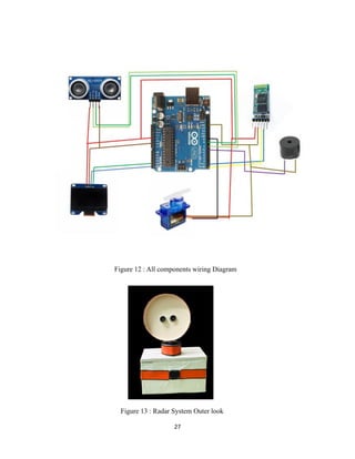
Figure 13 : All components wiring Diagram ................................................................................ 27
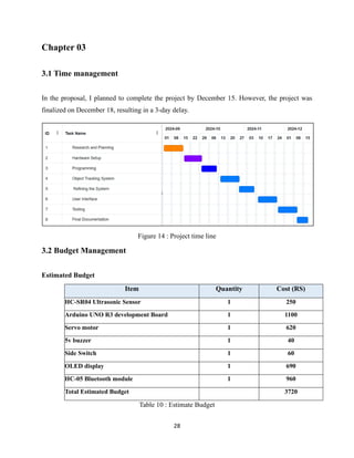
Figure 14 : Radar System Outer look ........................................................................................... 27
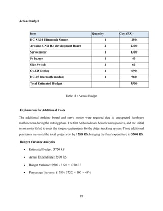
Figure 15 : Project time line.......................................................................................................... 28
5.
iv
List of Table
Table2: Power Supply Section in Arduino Bord........................................................................... 5
Table 3: Digital pins in Arduino Bord............................................................................................ 6
Table 4: Analog pins in Arduino Bord ............................................................................................ 6
Table 5 : Communication pins in Arduino Bord............................................................................. 7
Table 6 : HC-Ultrasonic sensor wiring Diagram .......................................................................... 25
Table 7 : Servo motor wiring Diagram ......................................................................................... 25
Table 8 : Buzzer Wiring Diagram ................................................................................................. 25
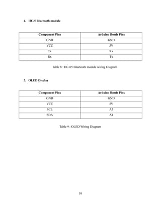
Table 9 : HC-05 Bluetooth module wiring Diagram .................................................................... 26
Table 10 : OLED Wiring Diagram................................................................................................ 26
Table 11 : Estimate Budget ........................................................................................................... 28
Table 12 : Actual Budget............................................................................................................... 29
6.
v
Contents
Acknowledgement.......................................................................................................................... i
Abstract..........................................................................................................................................ii
List ofFigure ................................................................................................................................iii
List of Table .................................................................................................................................. iv
Chapter 01 ..................................................................................................................................... 1
1.1 Introduction......................................................................................................................... 1
1.2 Objectives............................................................................................................................. 2
1.3 project features.................................................................................................................... 3
Chapter 02 ..................................................................................................................................... 4
2.1 Hardware components........................................................................................................ 4
2.1.1 Adrion uno Bord........................................................................................................... 4
2.1.2 Ultrasonic Sensor.......................................................................................................... 7
2.1.3 Servo Motor................................................................................................................. 10
2.1.4 OLED Display............................................................................................................. 12
2.1.5 Bluetooth Module ....................................................................................................... 14
2.1.6 Buzzer .......................................................................................................................... 16
2.2 Used Software .................................................................................................................... 17
2.2.1 Arduino IDE................................................................................................................ 17
2.2.2 MIT APP Innovator.................................................................................................... 22
2.3 Wiring Diagram of Project............................................................................................... 25
Chapter 03 ................................................................................................................................... 28
3.1 Time management ............................................................................................................. 28
3.2 Budget Management ......................................................................................................... 28
4 conclusions................................................................................................................................ 30
5 References................................................................................................................................. 31
7.
1
Chapter 01
1.1 Introduction
Radartechnology is widely used to detect and track objects in many areas, from security systems
to autonomous vehicles and industrial automation. Traditional radar systems rely on radio waves,
but this project, the ultrasonic radar system, takes a simpler and more affordable approach using
ultrasonic waves to detect obstacles and display real-time data.
At the heart of this system is an hc-sr04 ultrasonic sensor, which sends out sound waves and
measures the time it takes for them to bounce back after hitting an object. With this information,
the Arduino uno calculates the object's distance. The sensor is mounted on a servo motor, which
moves it back and forth, scanning the area just like a real radar system. The results are then
displayed on an OLED screen, making it easy to see detected objects.
To add more functionality, a Bluetooth module transmits the data to an android app, where users
can monitor the distance and angle of detected objects in real time. For added feedback, led bulbs
light up, and a buzzer sounds an alert when an obstacle is too close, making the system more
interactive and practical.
This project demonstrates how ultrasonic technology and wireless communication can work
together for effective object detection. Whether for security, automation, or robotics, this system
offers a simple, affordable, and useful way to detect obstacles and improve awareness.
8.
2
1.2 Objectives
The ultrasonicradar system aims to provide an easy-to-use, affordable solution for detecting
obstacles in real time. The key objectives of this project are:
• Create a simple radar system using an ultrasonic sensor to detect and measure the
distance to nearby objects.
• Enable a rotating scan with a servo motor, allowing the system to cover a wide area and
detect obstacles from different angles.
• Display real-time distance data clearly on an OLED screen so users can easily visualize
detected objects.
• Transmit data wirelessly via a Bluetooth module, sending object distance and angle to
an android app for easy remote monitoring.
• Add visual and audio alerts with led bulbs and a buzzer to notify users when obstacles
are detected.
• Build a practical, low-cost system that can be used in applications like security,
automation, and robotics.
• Learn and experiment with ultrasonic technology, wireless communication, and real-
time data processing while developing the system.
9.
3
1.3 project features
TheUltrasonic Radar System is packed with practical features that make it a user-friendly efficient
tool for detecting obstacles:
• Real-Time Object Detection: Using the ultrasonic sensor, the system instantly measures
the distance to nearby objects, giving you up-to-the-second data on obstacles.
• Rotating Scan: Thanks to the servo motor, the sensor rotates and scans the area, providing
a wider coverage for detecting obstacles from different angles.
• Clear Display: The OLED screen shows the distance to any detected objects, making it
easy for you to quickly visualize what's around.
• Wireless Data Transfer: The Bluetooth module sends the data directly to an Android app,
where you can see the distance and angle of objects in real time, all from the convenience
of your phone.
• Alert Notifications: If an obstacle is detected, the LED lights will turn on, and the buzzer
will sound, giving you both visual and audio alerts so you never miss anything.
• Easy to Use: The Android app provides a simple, intuitive interface that’s perfect for
anyone, whether you're a beginner or more experienced with technology.
• Affordable and Practical: A low-cost system that offers an easy solution for security,
automation, and robotics without breaking the bank.
• Portable and Lightweight: The system is compact and easy to move, making it versatile for
a variety of uses in different environments.
10.
4
Chapter 02
2.1 Hardwarecomponents
2.1.1 Adrion uno Bord
The Arduino Uno is a widely used microcontroller board based on the atmega328p chip. It comes
with 14 digital input/output pins, of which 6 support PWM output, along with 6 analog input pins
for reading sensor data. The board operates at 16 MHz, thanks to its built-in ceramic resonator
(CSTCE16M0V53-R0). It also features a USB connection for programming and power, a power
jack for external power sources, an ICSP header for low-level programming, and a reset button to
restart the system when needed.
What makes the Arduino Uno special is its ease of use. It includes everything necessary to run the
microcontroller, allowing users to simply connect it to a computer via USB or power it with an
AC-to-DC adapter or battery to get started. It’s also a great board for beginners because there's
little risk of permanently damaging it. Even if something goes wrong, the atmega328p chip can be
replaced for a few dollars, letting users start fresh.
The name "Uno", meaning "one" in Italian, was chosen to mark the release of Arduino Software
(IDE) 1.0. The Uno board and this early version of the Arduino IDE served as the foundation for
the Arduino platform, which has since evolved into newer versions. The Arduino Uno was the first
in a long line of USB-powered Arduino boards and remains the reference model for many
electronics and programming projects. For a complete list of past and present Arduino boards,
users can explore the Arduino board index.
11.
5
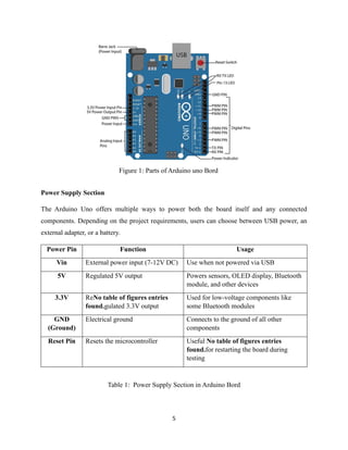
Power Supply Section
TheArduino Uno offers multiple ways to power both the board itself and any connected
components. Depending on the project requirements, users can choose between USB power, an
external adapter, or a battery.
Power Pin Function Usage
Vin External power input (7-12V DC) Use when not powered via USB
5V Regulated 5V output Powers sensors, OLED display, Bluetooth
module, and other devices
3.3V ReNo table of figures entries
found.gulated 3.3V output
Used for low-voltage components like
some Bluetooth modules
GND
(Ground)
Electrical ground Connects to the ground of all other
components
Reset Pin Resets the microcontroller Useful No table of figures entries
found.for restarting the board during
testing
Table 1: Power Supply Section in Arduino Bord
Figure 1: Parts of Arduino uno Bord
12.
6
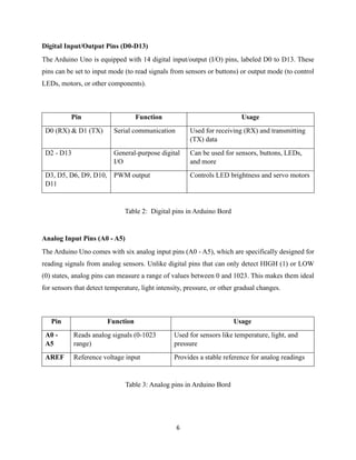
Digital Input/Output Pins(D0-D13)
The Arduino Uno is equipped with 14 digital input/output (I/O) pins, labeled D0 to D13. These
pins can be set to input mode (to read signals from sensors or buttons) or output mode (to control
LEDs, motors, or other components).
Pin Function Usage
D0 (RX) & D1 (TX) Serial communication Used for receiving (RX) and transmitting
(TX) data
D2 - D13 General-purpose digital
I/O
Can be used for sensors, buttons, LEDs,
and more
D3, D5, D6, D9, D10,
D11
PWM output Controls LED brightness and servo motors
Table 2: Digital pins in Arduino Bord
Analog Input Pins (A0 - A5)
The Arduino Uno comes with six analog input pins (A0 - A5), which are specifically designed for
reading signals from analog sensors. Unlike digital pins that can only detect HIGH (1) or LOW
(0) states, analog pins can measure a range of values between 0 and 1023. This makes them ideal
for sensors that detect temperature, light intensity, pressure, or other gradual changes.
Pin Function Usage
A0 -
A5
Reads analog signals (0-1023
range)
Used for sensors like temperature, light, and
pressure
AREF Reference voltage input Provides a stable reference for analog readings
Table 3: Analog pins in Arduino Bord
13.
7
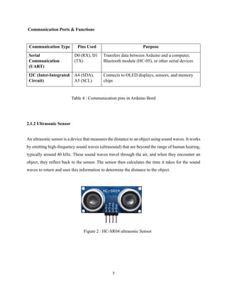
Figure 2 :HC-SR04 ultrasonic Sensor
Communication Ports & Functions
Communication Type Pins Used Purpose
Serial
Communication
(UART)
D0 (RX), D1
(TX)
Transfers data between Arduino and a computer,
Bluetooth module (HC-05), or other serial devices
I2C (Inter-Integrated
Circuit)
A4 (SDA),
A5 (SCL)
Connects to OLED displays, sensors, and memory
chips
Table 4 : Communication pins in Arduino Bord
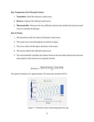
2.1.2 Ultrasonic Sensor
An ultrasonic sensor is a device that measures the distance to an object using sound waves. It works
by emitting high-frequency sound waves (ultrasound) that are beyond the range of human hearing,
typically around 40 kHz. These sound waves travel through the air, and when they encounter an
object, they reflect back to the sensor. The sensor then calculates the time it takes for the sound
waves to return and uses this information to determine the distance to the object.
14.
8
Figure 3 :Ultrasonic sensor transmitting and receiving
Key Components of an Ultrasonic Sensor:
1. Transmitter: Emits the ultrasonic sound waves.
2. Receiver: Captures the reflected sound waves.
3. Microcontroller: Processes the time difference between the emitted and received sound
waves to calculate the distance.
How It Works:
1. The transmitter sends out a burst of ultrasonic sound waves.
2. The sound waves travel through the air and hit an object.
3. The waves reflect off the object and return to the sensor.
4. The receiver detects the reflected sound waves.
5. The microcontroller calculates the distance based on the time delay between the emission
and reception of the sound waves using the formula:
𝐷𝑖𝑠𝑡𝑎𝑛𝑐𝑒 =
Speed of Sound × Time Delay
2
The speed of sound in air is approximately 343 meters per second (at 20°C).
15.
9
Advantages of UltrasonicSensors:
• Non-Contact Measurement: They can measure distance without physical contact with the
object.
• High Accuracy: They provide accurate distance measurements, especially for short to
medium ranges.
• Versatility: They can be used in various environments, including dark or dusty conditions
where optical sensors might fail.
• Low Cost: Ultrasonic sensors are relatively inexpensive compared to other types of
distance sensors.
Limitations of Ultrasonic Sensors:
• Limited Range: They are typically effective for distances up to a few meters.
• Environmental Factors: Temperature, humidity, and air pressure can affect the speed of
sound and thus the accuracy of the measurements.
• Surface Dependency: The accuracy can be affected by the texture and angle of the
object's surface. Soft or irregular surfaces may absorb or scatter the sound waves,
reducing the sensor's effectiveness.
16.
10
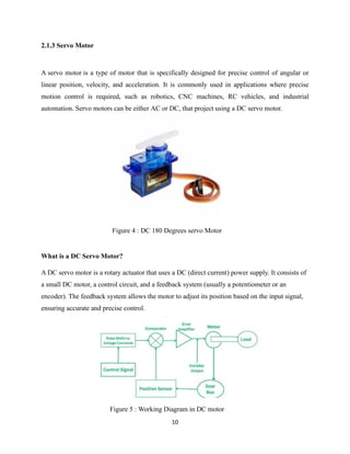
Figure 4 :DC 180 Degrees servo Motor
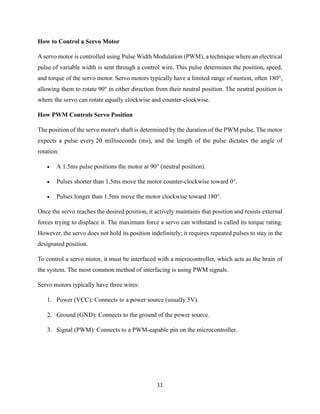
Figure 5 : Working Diagram in DC motor
2.1.3 Servo Motor
A servo motor is a type of motor that is specifically designed for precise control of angular or
linear position, velocity, and acceleration. It is commonly used in applications where precise
motion control is required, such as robotics, CNC machines, RC vehicles, and industrial
automation. Servo motors can be either AC or DC, that project using a DC servo motor.
What is a DC Servo Motor?
A DC servo motor is a rotary actuator that uses a DC (direct current) power supply. It consists of
a small DC motor, a control circuit, and a feedback system (usually a potentiometer or an
encoder). The feedback system allows the motor to adjust its position based on the input signal,
ensuring accurate and precise control.
17.
11
How to Controla Servo Motor
A servo motor is controlled using Pulse Width Modulation (PWM), a technique where an electrical
pulse of variable width is sent through a control wire. This pulse determines the position, speed,
and torque of the servo motor. Servo motors typically have a limited range of motion, often 180°,
allowing them to rotate 90° in either direction from their neutral position. The neutral position is
where the servo can rotate equally clockwise and counter-clockwise.
How PWM Controls Servo Position
The position of the servo motor's shaft is determined by the duration of the PWM pulse. The motor
expects a pulse every 20 milliseconds (ms), and the length of the pulse dictates the angle of
rotation:
• A 1.5ms pulse positions the motor at 90° (neutral position).
• Pulses shorter than 1.5ms move the motor counter-clockwise toward 0°.
• Pulses longer than 1.5ms move the motor clockwise toward 180°.
Once the servo reaches the desired position, it actively maintains that position and resists external
forces trying to displace it. The maximum force a servo can withstand is called its torque rating.
However, the servo does not hold its position indefinitely; it requires repeated pulses to stay in the
designated position.
To control a servo motor, it must be interfaced with a microcontroller, which acts as the brain of
the system. The most common method of interfacing is using PWM signals.
Servo motors typically have three wires:
1. Power (VCC): Connects to a power source (usually 5V).
2. Ground (GND): Connects to the ground of the power source.
3. Signal (PWM): Connects to a PWM-capable pin on the microcontroller.
18.
12
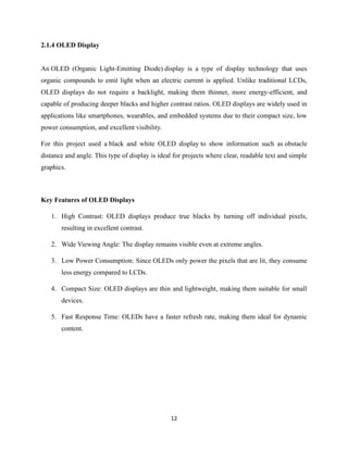
2.1.4 OLED Display
AnOLED (Organic Light-Emitting Diode) display is a type of display technology that uses
organic compounds to emit light when an electric current is applied. Unlike traditional LCDs,
OLED displays do not require a backlight, making them thinner, more energy-efficient, and
capable of producing deeper blacks and higher contrast ratios. OLED displays are widely used in
applications like smartphones, wearables, and embedded systems due to their compact size, low
power consumption, and excellent visibility.
For this project used a black and white OLED display to show information such as obstacle
distance and angle. This type of display is ideal for projects where clear, readable text and simple
graphics.
Key Features of OLED Displays
1. High Contrast: OLED displays produce true blacks by turning off individual pixels,
resulting in excellent contrast.
2. Wide Viewing Angle: The display remains visible even at extreme angles.
3. Low Power Consumption: Since OLEDs only power the pixels that are lit, they consume
less energy compared to LCDs.
4. Compact Size: OLED displays are thin and lightweight, making them suitable for small
devices.
5. Fast Response Time: OLEDs have a faster refresh rate, making them ideal for dynamic
content.
19.
13
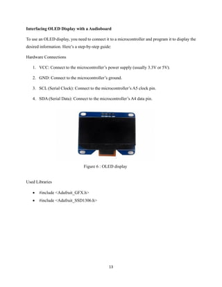
Figure 6 :OLED display
Interfacing OLED Display with a Audioboard
To use an OLED display, you need to connect it to a microcontroller and program it to display the
desired information. Here’s a step-by-step guide:
Hardware Connections
1. VCC: Connect to the microcontroller’s power supply (usually 3.3V or 5V).
2. GND: Connect to the microcontroller’s ground.
3. SCL (Serial Clock): Connect to the microcontroller’s A5 clock pin.
4. SDA (Serial Data): Connect to the microcontroller’s A4 data pin.
Used Libraries
• #include <Adafruit_GFX.h>
• #include <Adafruit_SSD1306.h>
20.
14
2.1.5 Bluetooth Module
ABluetooth module is a wireless communication device that enables data exchange between
electronic devices over short distances. It is commonly used in projects to establish a connection
between microcontrollers (like Arduino, ESP32, or Raspberry Pi) and smartphones, tablets, or
computers. In This project, the Bluetooth module is used to transmit data from an ultrasonic
sensor distance and a servo motor angle to a mobile app, allowing real-time monitoring and
control.
Key Features of Bluetooth Modules
1. Wireless Communication: Enables data transfer without physical cables.
2. Low Power Consumption: Ideal for battery-powered devices.
3. Ease of Use: Simple to interface with microcontrollers using serial communication
(UART).
4. Range: Typically, up to 10 meters (depending on the module and environment).
5. Compatibility: Works with most smartphones and computers.
Interfacing the Bluetooth Module with the Audioboard
The Bluetooth module is typically connected to the microcontroller via UART (Serial
Communication). Here’s how to connect it:
Hardware Connections
1. VCC: Connect to the microcontroller’s 5V or 3.3V power supply.
2. GND: Connect to the microcontroller’s ground.
3. TXD: Connect to the microcontroller’s RX pin.
4. RXD: Connect to the microcontroller’s TX
21.
15
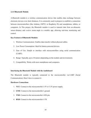
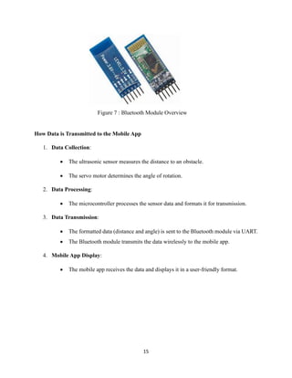
Figure 7 :Bluetooth Module Overview
How Data is Transmitted to the Mobile App
1. Data Collection:
• The ultrasonic sensor measures the distance to an obstacle.
• The servo motor determines the angle of rotation.
2. Data Processing:
• The microcontroller processes the sensor data and formats it for transmission.
3. Data Transmission:
• The formatted data (distance and angle) is sent to the Bluetooth module via UART.
• The Bluetooth module transmits the data wirelessly to the mobile app.
4. Mobile App Display:
• The mobile app receives the data and displays it in a user-friendly format.
22.
16
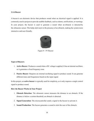
Figure 8 :5V Buzzer
2.1.6 Buzzer
A buzzer is an electronic device that produces sound when an electrical signal is applied. It is
commonly used in projects to provide audible feedback, such as alarms, notifications, or warnings.
In your project, the buzzer is used to generate a sound when an obstacle is detected by
the ultrasonic sensor. This helps alert users to the presence of an obstacle, making the system more
interactive and user-friendly.
Types of Buzzers
1. Active Buzzer: Produces a sound when a DC voltage is applied. It has an internal oscillator,
so it generates a fixed frequency tone.
2. Passive Buzzer: Requires an external oscillating signal to produce sound. It can generate
different tones and frequencies based on the input signal.
In this project, an active buzzer is typically used for simplicity, as it only requires a single control
signal to produce sound.
How the Buzzer Works in Your Project
1. Obstacle Detection: The ultrasonic sensor measures the distance to an obstacle. If the
distance is below a certain threshold, an obstacle is detected.
2. Signal Generation: The microcontroller sends a signal to the buzzer to activate it.
3. Sound Production: The buzzer generates a sound to alert the user of the obstacle.
23.
17
Connecting the Buzzerto an Arduino Board
The buzzer is connected to the Arduino's digital pin (e.g., pin 6) to control its operation.
1.Positive Terminal (VCC): Connect to the Arduino’s digital pin (e.g., pin 6).
2.Negative Terminal (GND): Connect to the Arduino’s ground (GND).
2.2 Used Software
2.2.1 Arduino IDE
The Arduino IDE (Integrated Development Environment) is a software platform used to write,
compile, and upload code to Arduino boards and other compatible microcontrollers. It is a user-
friendly tool designed for both beginners and advanced users, making it one of the most popular
development environments for electronics and IoT projects.
Components of the Arduino IDE
1. Code Editor: Where you write and edit your code (also called a sketch).
2. Toolbar: Contains buttons for common tasks like verifying, uploading, and opening
sketches.
3. Serial Monitor: Displays data sent from the Arduino board via serial communication.
4. Library Manager: Allows you to install and manage additional libraries.
5. Board Manager: Lets you add support for new boards and architectures.
24.
18
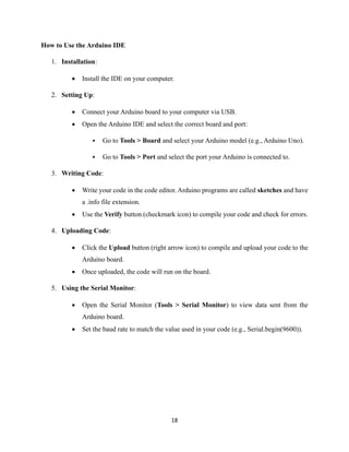
How to Usethe Arduino IDE
1. Installation:
• Install the IDE on your computer.
2. Setting Up:
• Connect your Arduino board to your computer via USB.
• Open the Arduino IDE and select the correct board and port:
▪ Go to Tools > Board and select your Arduino model (e.g., Arduino Uno).
▪ Go to Tools > Port and select the port your Arduino is connected to.
3. Writing Code:
• Write your code in the code editor. Arduino programs are called sketches and have
a .info file extension.
• Use the Verify button (checkmark icon) to compile your code and check for errors.
4. Uploading Code:
• Click the Upload button (right arrow icon) to compile and upload your code to the
Arduino board.
• Once uploaded, the code will run on the board.
5. Using the Serial Monitor:
• Open the Serial Monitor (Tools > Serial Monitor) to view data sent from the
Arduino board.
• Set the baud rate to match the value used in your code (e.g., Serial.begin(9600)).
25.
19
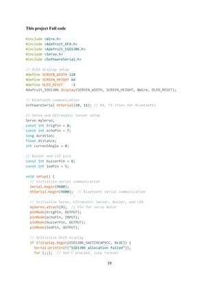
This project Fullcode
#include <Wire.h>
#include <Adafruit_GFX.h>
#include <Adafruit_SSD1306.h>
#include <Servo.h>
#include <SoftwareSerial.h>
// OLED display setup
#define SCREEN_WIDTH 128
#define SCREEN_HEIGHT 64
#define OLED_RESET -1
Adafruit_SSD1306 display(SCREEN_WIDTH, SCREEN_HEIGHT, &Wire, OLED_RESET);
// Bluetooth communication
SoftwareSerial btSerial(10, 11); // RX, TX (Pins for Bluetooth)
// Servo and Ultrasonic Sensor setup
Servo myServo;
const int trigPin = 8;
const int echoPin = 7;
long duration;
float distance;
int currentAngle = 0;
// Buzzer and LED pins
const int buzzerPin = 6;
const int ledPin = 5;
void setup() {
// Initialize serial communication
Serial.begin(9600);
btSerial.begin(9600); // Bluetooth serial communication
// Initialize Servo, Ultrasonic Sensor, Buzzer, and LED
myServo.attach(9); // Pin for servo motor
pinMode(trigPin, OUTPUT);
pinMode(echoPin, INPUT);
pinMode(buzzerPin, OUTPUT);
pinMode(ledPin, OUTPUT);
// Initialize OLED display
if (!display.begin(SSD1306_SWITCHCAPVCC, 0x3C)) {
Serial.println(F("SSD1306 allocation failed"));
for (;;); // Don't proceed, loop forever
26.
20
}
display.display(); // Showinitial splash screen
delay(2000); // Pause for 2 seconds
// Clear display
display.clearDisplay();
// Initialize Bluetooth
Serial.println("Radar System with Bluetooth Initialized");
}
void loop() {
// Sweep the servo motor
for (int angle = 0; angle <= 180; angle += 10) {
scanAndSendData(angle);
}
for (int angle = 180; angle >= 0; angle -= 10) {
scanAndSendData(angle);
}
}
void scanAndSendData(int angle) {
// Move servo motor to the specified angle
myServo.write(angle);
delay(500); // Wait for servo stabilization
// Measure distance using ultrasonic sensor
digitalWrite(trigPin, LOW);
delayMicroseconds(2);
digitalWrite(trigPin, HIGH);
delayMicroseconds(10);
digitalWrite(trigPin, LOW);
duration = pulseIn(echoPin, HIGH);
distance = (duration * 0.034) / 2; // Convert to centimeters
// Trigger buzzer and LED for objects within 20 cm
if (distance < 50) {
digitalWrite(buzzerPin, HIGH); // Turn on buzzer
digitalWrite(ledPin, HIGH); // Turn on LED
btSerial.println("Buzzer: ON | LED: ON");
} else {
digitalWrite(buzzerPin, LOW); // Turn off buzzer
digitalWrite(ledPin, LOW); // Turn off LED
btSerial.println("Buzzer: OFF | LED: OFF");
27.
21
}
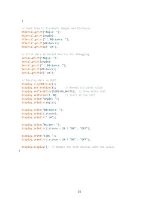
// Send datato Bluetooth (Angle and Distance)
btSerial.print("Angle: ");
btSerial.print(angle);
btSerial.print(" | Distance: ");
btSerial.print(distance);
btSerial.println(" cm");
// Print data to Serial Monitor for debugging
Serial.print("Angle: ");
Serial.print(angle);
Serial.print(" | Distance: ");
Serial.print(distance);
Serial.println(" cm");
// Display data on OLED
display.clearDisplay();
display.setTextSize(1); // Normal 1:1 pixel scale
display.setTextColor(SSD1306_WHITE); // Draw white text
display.setCursor(0, 0); // Start at top left
display.print("Angle: ");
display.println(angle);
display.print("Distance: ");
display.print(distance);
display.println(" cm");
display.print("Buzzer: ");
display.println(distance < 20 ? "ON" : "OFF");
display.print("LED: ");
display.println(distance < 20 ? "ON" : "OFF");
display.display(); // Update the OLED display with new values
}
28.
22
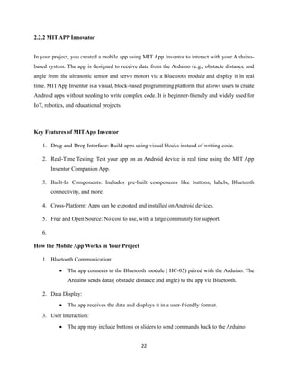
2.2.2 MIT APPInnovator
In your project, you created a mobile app using MIT App Inventor to interact with your Arduino-
based system. The app is designed to receive data from the Arduino (e.g., obstacle distance and
angle from the ultrasonic sensor and servo motor) via a Bluetooth module and display it in real
time. MIT App Inventor is a visual, block-based programming platform that allows users to create
Android apps without needing to write complex code. It is beginner-friendly and widely used for
IoT, robotics, and educational projects.
Key Features of MIT App Inventor
1. Drag-and-Drop Interface: Build apps using visual blocks instead of writing code.
2. Real-Time Testing: Test your app on an Android device in real time using the MIT App
Inventor Companion App.
3. Built-In Components: Includes pre-built components like buttons, labels, Bluetooth
connectivity, and more.
4. Cross-Platform: Apps can be exported and installed on Android devices.
5. Free and Open Source: No cost to use, with a large community for support.
6.
How the Mobile App Works in Your Project
1. Bluetooth Communication:
• The app connects to the Bluetooth module ( HC-05) paired with the Arduino. The
Arduino sends data ( obstacle distance and angle) to the app via Bluetooth.
2. Data Display:
• The app receives the data and displays it in a user-friendly format.
3. User Interaction:
• The app may include buttons or sliders to send commands back to the Arduino
29.
23
Figure 9 :Mobile App Interface creating in MIT App
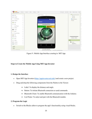
Steps to Create the Mobile App Using MIT App Inventor
1. Design the Interface
• Open MIT App Inventor (https://appinventor.mit.edu/) and create a new project.
• Drag and drop the following components from the Palette to the Viewer:
• Label: To display the distance and angle.
• Button: To initiate Bluetooth connection or send commands.
• Bluetooth Client: To enable Bluetooth communication with the Arduino.
• List Picker: To select and pair with the Bluetooth module.
2. Program the Logic
• Switch to the Blocks editor to program the app’s functionality using visual blocks.
30.
24
Figure 11 :Mobile App testing
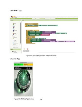
3. Blocks for App
Figure 10 : Block Diagram for radar mobile app
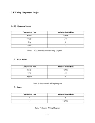
4. Test the App
23.23 cm 36.12
27
Figure 13 :Radar System Outer look
Figure 12 : All components wiring Diagram
34.
28
Chapter 03
3.1 Timemanagement
In the proposal, I planned to complete the project by December 15. However, the project was
finalized on December 18, resulting in a 3-day delay.
Figure 14 : Project time line
3.2 Budget Management
Estimated Budget
Item Quantity Cost (RS)
HC-SR04 Ultrasonic Sensor 1 250
Arduino UNO R3 development Board 1 1100
Servo motor 1 620
5v buzzer 1 40
Side Switch 1 60
OLED display 1 690
HC-05 Bluetooth module 1 960
Total Estimated Budget 3720
Table 10 : Estimate Budget
35.
29
Actual Budget
Item QuantityCost (RS)
HC-SR04 Ultrasonic Sensor 1 250
Arduino UNO R3 development Board 2 2200
Servo motor 1 1300
5v buzzer 1 40
Side Switch 1 60
OLED display 1 690
HC-05 Bluetooth module 1 960
Total Estimated Budget 5500
Table 11 : Actual Budget
Explanation for Additional Costs
The additional Arduino board and servo motor were required due to unexpected hardware
malfunctions during the testing phase. The firstArduino board became unresponsive, and the initial
servo motor failed to meet the torque requirements for the object tracking system. These additional
purchases increased the total project cost by 1780 RS, bringing the final expenditure to 5500 RS.
Budget Variance Analysis
• Estimated Budget: 3720 RS
• Actual Expenditure: 5500 RS
• Budget Variance: 5500 - 3720 = 1780 RS
• Percentage Increase: (1780 / 3720) × 100 = 48%
36.
30
The project exceededthe estimated budget by 1780 RS, representing a 48% increase. This
variance was primarily due to the need for additional hardware components to address technical
challenges. While this increased the overall cost, it ensured the successful completion of the
project.
4. conclusions
In this project, I successfully built an ultrasonic radar system to measure distances and
detect objects. By using components like an ultrasonic sensor, a servo motor, an Arduino
board, a buzzer, and LEDs, I was able to create a functional and effective tool.
I carefully selected and assembled the parts, wrote and tested the code, and made sure
everything worked together properly. The project was completed within the planned
budget, covering all necessary parts and additional costs.
This project meets its goals and shows that a simple setup can be very effective. There are
also opportunities to improve it further, like adding wireless features or making it suitable
for outdoor use. Overall, this project demonstrates how combining basic technology can
result in a useful and practical system.

![31
5. References
[1] "geeksforgeeks," 22 april 2024. [Online]. Available:
https://www.geeksforgeeks.org/overview-of-the-arduino-uno-components/.
[2] geeksforgee, 27 February 2024. [Online]. Available: https://www.geeksforgeeks.org/servo-
motor/.
[3] [Online]. Available: https://robocraze.com/blogs/post/what-is-ultrasonic-sensor.
[4] "instructables," [Online]. Available: https://www.instructables.com/OLED-I2C-DISPLAY-WITH-
ARDUINO-Tutorial/.
[5] "mit app," [Online]. Available: http://www.appinventor.mit.edu/explore/ai2/tutorials.html.
[6] "github," [Online]. Available: https://github.com/OwenAtConestoga/Radar-System.](https://image.slidesharecdn.com/finalreportradarsystem-250315050242-eb18744f/85/Final-Report-Ultrasonic-Radar-System-pdf-37-320.jpg)