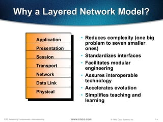
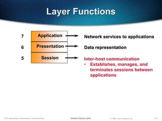
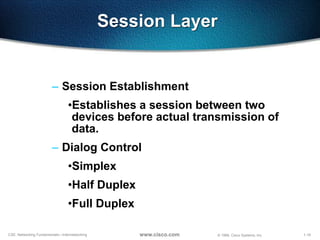
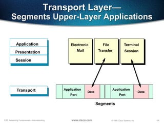
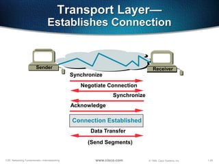
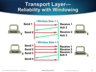
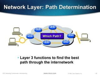
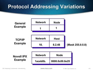
© 1999, Cisco Systems, Inc.www.cisco.com
Networking Basics
1-2CSE: Networking Fundamentals—Internetworking © 1999, Cisco Systems, Inc.www.cisco.com
The OSI Model
• OSI Layer is meant for Networking
manufacturers and developers to
provide them a standard based on
which they can make their products.
• All OSI Layers are independent from
each other, which makes introducing
changes easier as no other layers are
effected.
• Ease of Troubleshooting.
© 1999, Cisco Systems, Inc.www.cisco.com
The Layered Model
© 1999, Cisco Systems, Inc. www.cisco.com
1-4CSE: Networking Fundamentals—Internetworking © 1999, Cisco Systems, Inc.www.cisco.com
Why a Layered Network Model?
7 Application
6 Presentation
5 Session
4 Transport
3 Network
2 Data Link
1 Physical
• Reduces complexity (one big
problem to seven smaller
ones)
• Standardizes interfaces
• Facilitates modular
engineering
• Assures interoperable
technology
• Accelerates evolution
• Simplifies teaching and
learning
1-5CSE: Networking Fundamentals—Internetworking © 1999, Cisco Systems, Inc.www.cisco.com
Devices Function at Layers
7 Application
6 Presentation
5 Session
4 Transport
3 Network
2 Data Link
1 Physical
NIC Card
Hub
1-6CSE: Networking Fundamentals—Internetworking © 1999, Cisco Systems, Inc.www.cisco.com
Host Layers
7 Application
6 Presentation
5 Session
4 Transport
Network
3 Data Link
1
Host layers: Provide
accurate data delivery
between computers}
Physical
1-7CSE: Networking Fundamentals—Internetworking © 1999, Cisco Systems, Inc.www.cisco.com
Media Layers
7 Application
6 Presentation
5 Session
4
Transport
3 Network
2 Data Link
1 Physical
Host layers: Provide
accurate data delivery
between computers
Media layers: Control
physical delivery of messages
over the network
}
}
1-8CSE: Networking Fundamentals—Internetworking © 1999, Cisco Systems, Inc.www.cisco.com
Layer Functions
Provides network services to
application processes (such as
electronic mail, file transfer, and
terminal emulation)
7 Application
1-9CSE: Networking Fundamentals—Internetworking © 1999, Cisco Systems, Inc.www.cisco.com
Layer Functions
Network services to applications
• Ensures data is readable by
receiving system
• Format of data
• Data structures
• Negotiates data transfer
syntax for application layer
7 Application
6 Presentation Data representation
1-10CSE: Networking Fundamentals—Internetworking © 1999, Cisco Systems, Inc.www.cisco.com
Layer Functions
Inter-host communication
• Establishes, manages, and
terminates sessions between
applications
7 Application
6 Presentation
5 Session
Network services to applications
Data representation
1-11CSE: Networking Fundamentals—Internetworking © 1999, Cisco Systems, Inc.www.cisco.com
Layer Functions
7 Application
6 Presentation
5 Session
Transport4
Inter-host communication
Network services to applications
Data representation
End-to-end connection reliability
• Concerned with data transport
issues between hosts
• Data transport reliability
• Establishes, maintains, and
terminates virtual circuits
• Fault detection and recovery
• Information flow control
1-12CSE: Networking Fundamentals—Internetworking © 1999, Cisco Systems, Inc.www.cisco.com
Layer Functions
7 Application
6 Presentation
5 Session
Transport4
Network3
Inter-host communication
Network services to applications
Data representation
End-to-end connection reliability
Addresses and best path
• Provides connectivity and path
selection between two end
systems
• Domain of routing
1-13CSE: Networking Fundamentals—Internetworking © 1999, Cisco Systems, Inc.www.cisco.com
Layer Functions
7 Application
6 Presentation
5 Session
Transport4
Network3
Data Link2
Inter-host communication
Network services to applications
Data representation
End-to-end connection reliability
Addresses and best path
Access to media
• Provides reliable transfer of data
across media
• Physical addressing, network
topology, error notification, flow
control
1-14CSE: Networking Fundamentals—Internetworking © 1999, Cisco Systems, Inc.www.cisco.com
Layer Functions
7 Application
6 Presentation
5 Session
Transport4
Network3
Data Link2
Physical1
Inter-host communication
Network services to applications
Data representation
End-to-end connection reliability
Addresses and best path
Access to media
Binary transmission
• Wires, connectors, voltages,
data rates
1-15CSE: Networking Fundamentals—Internetworking © 1999, Cisco Systems, Inc.www.cisco.com
7 Application
6 Presentation
5 Session
4 Transport
3 Network
2 Data Link
1 Physical
Host A
Peer-to-Peer Communications
Application
Presentation
Session
Transport
Network
Data Link
PhysicalBits
Frames
Packets
Segments
Host B
1-16CSE: Networking Fundamentals—Internetworking © 1999, Cisco Systems, Inc.www.cisco.com
Application Layer
• This is where users communicate to the
computer.
• This is where communication between
two users are established.
• This is a point where user or application
interfaces with the protocols to gain
access to the network.
• Examples are WWW, Telnet, FTP, TFTP,
E-mail, SNMP, DNS
1-17CSE: Networking Fundamentals—Internetworking © 1999, Cisco Systems, Inc.www.cisco.com
Presentation Layer
• Tasks like Translation, Encryption,
decryption, compression, decompression are
associated with this layer.
• It receives the data in native format &
converts in standard format or receives data
in standard format and converts in native
format, ie. EBCDIC(Extended Binary code
Decimal Interchange Code) to ASCII.
• It is mainly responsible for how the data is to
be presented to the Application Layer.
• Examples are PICT, TIFF, JPEG, MIDI, MPEG,
GIFF etc.
1-18CSE: Networking Fundamentals—Internetworking © 1999, Cisco Systems, Inc.www.cisco.com
Presentation Layer
ASCII
EBCDIC
Encrypted
• Text
• Data
login:
PICT
TIFF
JPEG
GIF
• Graphics
• Visual images
• Sound
• Video
MPEG
QuickTime
MIDI
• Provides code formatting and
conversion for applications
1-19CSE: Networking Fundamentals—Internetworking © 1999, Cisco Systems, Inc.www.cisco.com
Session Layer
– Session Establishment
•Establishes a session between two
devices before actual transmission of
data.
– Dialog Control
•Simplex
•Half Duplex
•Full Duplex
1-20CSE: Networking Fundamentals—Internetworking © 1999, Cisco Systems, Inc.www.cisco.com
Session Layer
• Network File System (NFS)
• Structured Query Language (SQL)
• Remote-Procedure Call (RPC)
• X Window System
• AppleTalk Session Protocol (ASP)
• DEC Session Control Protocol (SCP)
Service Request
Service Reply
• Coordinates applications as
they interact on different hosts
1-21CSE: Networking Fundamentals—Internetworking © 1999, Cisco Systems, Inc.www.cisco.com
Transport Layer
• Segments upper-layer applications
• Establishes an end-to-end connection
• Sends segments from one end host to another
• Optionally, ensures data reliability
1-22CSE: Networking Fundamentals—Internetworking © 1999, Cisco Systems, Inc.www.cisco.com
Transport Layer
• Transport Layer never actually transports the data
but only prepares for transporting.
• Uses Socket to define the services running on a
particular node, the data is associated with.
• Responsible for the following :
– Segmentation
– End-to-end Communication
– Flow Control
– Error Control
– Multiplexing of Applications
• TCP, UDP and SPX work at this layer
1-23CSE: Networking Fundamentals—Internetworking © 1999, Cisco Systems, Inc.www.cisco.com
Socket
• Socket is a software component and points to a particular service
running on a particular node.
• Structure of a socket
– IP Address + Port Address
• Each service has a unique Port address
• Max. Port Addresses can be 65,536
• Port address 1-1023 is reserved for specific Services like
– WWW - 80
– FTP - 21
– SMTP - 25
• Port Addresses are reserved for standardization purpose.
1-24CSE: Networking Fundamentals—Internetworking © 1999, Cisco Systems, Inc.www.cisco.com
Transport Layer—
Segments Upper-Layer Applications
Electronic
Mail
File
Transfer
Application
Presentation
Session
Segments
Data
Application
Port
Transport Data
Application
Port
Terminal
Session
1-25CSE: Networking Fundamentals—Internetworking © 1999, Cisco Systems, Inc.www.cisco.com
Port Numbers
TCP
Port
Numbers
F
T
P
Transport
Layer
T
E
L
N
E
T
D
N
S
S
N
M
P
T
F
T
P
S
M
T
P
UDP
Application
Layer
21 23 25 53 69 161
R
I
P
520
1-26CSE: Networking Fundamentals—Internetworking © 1999, Cisco Systems, Inc.www.cisco.com
Segmentation
• This is a mechanism wherein the data is divided into
multiple segments and sent over the network.
• By doing this different segments can use different links
for travelling across the network.
• If one segment is lost the only segment is required to be
re-sent and not the entire data.
• Once all segments reach to the destination the received
segments have to be sequenced back, which is also
done at this layer.
1-27CSE: Networking Fundamentals—Internetworking © 1999, Cisco Systems, Inc.www.cisco.com
Transport Layer—
Sends Segments with Flow Control
Transmit
Buffer Full
Not Ready
Stop
Process
Segments
Buffer OK
ReadyGo
Resume Transmission
ReceiverSender
1-28CSE: Networking Fundamentals—Internetworking © 1999, Cisco Systems, Inc.www.cisco.com
Flow Control
• Used while connection oriented communication
• It helps to have a control on over flow of Buffer.
• Advantages are:
– The segments delivered are acknowledged if received
– Any segment not acknowledged are retransmitted
– segments are sequenced back upon their arrival
– Congestion, Overloading and data loss are avoided
• To achieve all this it uses the technique of Sliding
window or Windowing
1-29CSE: Networking Fundamentals—Internetworking © 1999, Cisco Systems, Inc.www.cisco.com
Transport Layer—
Establishes Connection
Synchronize
Synchronize
Acknowledge
Negotiate Connection
Receiver
Data Transfer
Connection Established
(Send Segments)
Sender
1-30CSE: Networking Fundamentals—Internetworking © 1999, Cisco Systems, Inc.www.cisco.com
End-to-End Communication
• Connection Less Transmission
–UDP is used
–Not reliable
–Faster
• Connection Oriented Transmission
–TCP or SPX is used
–Reliable
–Slower
1-31CSE: Networking Fundamentals—Internetworking © 1999, Cisco Systems, Inc.www.cisco.com
Connection Oriented Protocol
• These protocols relies on Acknowledgement.
• Positive acknowledgement means data has
been received.
• Negative acknowledgement means data is
lost no further data is sent till positive
acknowledgement is received.
• It is slow but Reliable.
• Eg. TCP and SPX
1-32CSE: Networking Fundamentals—Internetworking © 1999, Cisco Systems, Inc.www.cisco.com
Transport Layer—
Reliability with Windowing
• Window Size = 1
Sender
Send 1 Receive 1
Receiver
Ack 2
Send 2 Receive 2
Ack 3
Sender
Send 1
Send 2
Receive 1
Receive 2
Receiver
• Window Size = 3
Send 3 Receive 3
Ack 4
Send 4
1-33CSE: Networking Fundamentals—Internetworking © 1999, Cisco Systems, Inc.www.cisco.com
Transport Layer—
An Acknowledgement Technique
Sender Receiver
Send 2
Send 1
Send 3
Ack 4
Send 5
Send 4
Send 6
Ack 5
Send 5
Ack 7
1 2 3 4 5 6 7 1 2 3 4 5 6 7
1-34CSE: Networking Fundamentals—Internetworking © 1999, Cisco Systems, Inc.www.cisco.com
Connection Less Protocol
• They do not provide acknowledgement
neither sequence numbers.
• It is faster but not reliable
• Eg. UDP
1-35CSE: Networking Fundamentals—Internetworking © 1999, Cisco Systems, Inc.www.cisco.com
Network Layer
• It is responsible for communicating Networks
• It recognizes Networks with the help of Netwok Addresses
– Network Address is a logical address like IP Address or IPX
Address
– It is common for a group of computers
• It works only with Network IDs and has got nothing to do with host
Ids.
• Path determination or Routing is performed at this layer.
• Router works at this layer.
1-36CSE: Networking Fundamentals—Internetworking © 1999, Cisco Systems, Inc.www.cisco.com
Network Layer: Path Determination
Which Path?Which Path?
• Layer 3 functions to find the best
path through the internetwork
1-37CSE: Networking Fundamentals—Internetworking © 1999, Cisco Systems, Inc.www.cisco.com
Network Layer: Communicate Path
1
2
3
4
5
6
7
8
9
10 11
• Addresses represent the path of media
connections
1-38CSE: Networking Fundamentals—Internetworking © 1999, Cisco Systems, Inc.www.cisco.com
Addressing—Network and Node
Network Node
1
2
1
2
3
1
3 1
1.1
2.1
3.1
1.2
1.3
• Network address—Path part used by the router
• Node address—Specific port or device on the network
1-39CSE: Networking Fundamentals—Internetworking © 1999, Cisco Systems, Inc.www.cisco.com
Protocol Addressing Variations
Network Node
1 1
General
Example
Network Host
10. 8.2.48
TCP/IP
Example (Mask 255.0.0.0)
Network Node
1aceb0b. 0000.0c00.6e25
Novell IPX
Example
1-40CSE: Networking Fundamentals—Internetworking © 1999, Cisco Systems, Inc.www.cisco.com
Network Layer
Protocol Operations
• Each router provides its services to
support upper layer functions
X Y
AA
CC
1-41CSE: Networking Fundamentals—Internetworking © 1999, Cisco Systems, Inc.www.cisco.com
Routed Versus Routing Protocol
• Routed protocol
used between
routers to direct
user traffic
Examples: IP, IPX,
AppleTalk
• Routing protocol
used only between
routers to maintain
routing tables
Examples: RIP, IGRP, OSPF
1-42CSE: Networking Fundamentals—Internetworking © 1999, Cisco Systems, Inc.www.cisco.com
Static Versus Dynamic Routes
Uses a protocol route that a network
administrator enters into the router
Static Route
Uses a route that a network protocol
adjusts automatically for topology or
traffic changes
Dynamic Route
1-43CSE: Networking Fundamentals—Internetworking © 1999, Cisco Systems, Inc.www.cisco.com
Static Route Example
Point-to-point or
circuit-switched
connection
“Stub” network
Only a single network
connection with no need
for routing updates
AA
BB
• Fixed route to address reflects
administrator’s knowledge
1-44CSE: Networking Fundamentals—Internetworking © 1999, Cisco Systems, Inc.www.cisco.com
Adapting to Topology Change
AA BB
CCDD
• Can an alternate route substitute
for a failed route?
1-45CSE: Networking Fundamentals—Internetworking © 1999, Cisco Systems, Inc.www.cisco.com
Adapting to Topology Change
AA BB
CCDD
XX
1-46CSE: Networking Fundamentals—Internetworking © 1999, Cisco Systems, Inc.www.cisco.com
Adapting to Topology Change
AA BB
CCDD
XX
• Can an alternate route substitute
for a failed route?
Yes—With dynamic routing enabled
1-47CSE: Networking Fundamentals—Internetworking © 1999, Cisco Systems, Inc.www.cisco.com
Data Link Layer
• It uniquely identifies each device in the Network.
• It translates data from Network Layer into bits for the
Physical layer to transmit.
• It formats the messages into Data Frames
• Adds a customized header containing Source and
Destination hardware address
• This layer works with Frames
This layer is logically divided in two sub-layers:
LLC (Logical Link Control)
MAC (Media Access Control)
1-48CSE: Networking Fundamentals—Internetworking © 1999, Cisco Systems, Inc.www.cisco.com
Physical Layer
• Electrical and Mechanical settings are provided at this
layer.
• Transmits data in the form of bits.
• This layer communicates directly with actual
communication media.
• At this layer DCE & DTE are identified
• HUBs & REPEATERS works at this layer.
• Max. troubleshooting occurs at this layer.

QSpiders - Day1 Network Basics

  • 1.
    © 1999, CiscoSystems, Inc.www.cisco.com Networking Basics
  • 2.
    1-2CSE: Networking Fundamentals—Internetworking© 1999, Cisco Systems, Inc.www.cisco.com The OSI Model • OSI Layer is meant for Networking manufacturers and developers to provide them a standard based on which they can make their products. • All OSI Layers are independent from each other, which makes introducing changes easier as no other layers are effected. • Ease of Troubleshooting.
  • 3.
    © 1999, CiscoSystems, Inc.www.cisco.com The Layered Model © 1999, Cisco Systems, Inc. www.cisco.com
  • 4.
    1-4CSE: Networking Fundamentals—Internetworking© 1999, Cisco Systems, Inc.www.cisco.com Why a Layered Network Model? 7 Application 6 Presentation 5 Session 4 Transport 3 Network 2 Data Link 1 Physical • Reduces complexity (one big problem to seven smaller ones) • Standardizes interfaces • Facilitates modular engineering • Assures interoperable technology • Accelerates evolution • Simplifies teaching and learning
  • 5.
    1-5CSE: Networking Fundamentals—Internetworking© 1999, Cisco Systems, Inc.www.cisco.com Devices Function at Layers 7 Application 6 Presentation 5 Session 4 Transport 3 Network 2 Data Link 1 Physical NIC Card Hub
  • 6.
    1-6CSE: Networking Fundamentals—Internetworking© 1999, Cisco Systems, Inc.www.cisco.com Host Layers 7 Application 6 Presentation 5 Session 4 Transport Network 3 Data Link 1 Host layers: Provide accurate data delivery between computers} Physical
  • 7.
    1-7CSE: Networking Fundamentals—Internetworking© 1999, Cisco Systems, Inc.www.cisco.com Media Layers 7 Application 6 Presentation 5 Session 4 Transport 3 Network 2 Data Link 1 Physical Host layers: Provide accurate data delivery between computers Media layers: Control physical delivery of messages over the network } }
  • 8.
    1-8CSE: Networking Fundamentals—Internetworking© 1999, Cisco Systems, Inc.www.cisco.com Layer Functions Provides network services to application processes (such as electronic mail, file transfer, and terminal emulation) 7 Application
  • 9.
    1-9CSE: Networking Fundamentals—Internetworking© 1999, Cisco Systems, Inc.www.cisco.com Layer Functions Network services to applications • Ensures data is readable by receiving system • Format of data • Data structures • Negotiates data transfer syntax for application layer 7 Application 6 Presentation Data representation
  • 10.
    1-10CSE: Networking Fundamentals—Internetworking© 1999, Cisco Systems, Inc.www.cisco.com Layer Functions Inter-host communication • Establishes, manages, and terminates sessions between applications 7 Application 6 Presentation 5 Session Network services to applications Data representation
  • 11.
    1-11CSE: Networking Fundamentals—Internetworking© 1999, Cisco Systems, Inc.www.cisco.com Layer Functions 7 Application 6 Presentation 5 Session Transport4 Inter-host communication Network services to applications Data representation End-to-end connection reliability • Concerned with data transport issues between hosts • Data transport reliability • Establishes, maintains, and terminates virtual circuits • Fault detection and recovery • Information flow control
  • 12.
    1-12CSE: Networking Fundamentals—Internetworking© 1999, Cisco Systems, Inc.www.cisco.com Layer Functions 7 Application 6 Presentation 5 Session Transport4 Network3 Inter-host communication Network services to applications Data representation End-to-end connection reliability Addresses and best path • Provides connectivity and path selection between two end systems • Domain of routing
  • 13.
    1-13CSE: Networking Fundamentals—Internetworking© 1999, Cisco Systems, Inc.www.cisco.com Layer Functions 7 Application 6 Presentation 5 Session Transport4 Network3 Data Link2 Inter-host communication Network services to applications Data representation End-to-end connection reliability Addresses and best path Access to media • Provides reliable transfer of data across media • Physical addressing, network topology, error notification, flow control
  • 14.
    1-14CSE: Networking Fundamentals—Internetworking© 1999, Cisco Systems, Inc.www.cisco.com Layer Functions 7 Application 6 Presentation 5 Session Transport4 Network3 Data Link2 Physical1 Inter-host communication Network services to applications Data representation End-to-end connection reliability Addresses and best path Access to media Binary transmission • Wires, connectors, voltages, data rates
  • 15.
    1-15CSE: Networking Fundamentals—Internetworking© 1999, Cisco Systems, Inc.www.cisco.com 7 Application 6 Presentation 5 Session 4 Transport 3 Network 2 Data Link 1 Physical Host A Peer-to-Peer Communications Application Presentation Session Transport Network Data Link PhysicalBits Frames Packets Segments Host B
  • 16.
    1-16CSE: Networking Fundamentals—Internetworking© 1999, Cisco Systems, Inc.www.cisco.com Application Layer • This is where users communicate to the computer. • This is where communication between two users are established. • This is a point where user or application interfaces with the protocols to gain access to the network. • Examples are WWW, Telnet, FTP, TFTP, E-mail, SNMP, DNS
  • 17.
    1-17CSE: Networking Fundamentals—Internetworking© 1999, Cisco Systems, Inc.www.cisco.com Presentation Layer • Tasks like Translation, Encryption, decryption, compression, decompression are associated with this layer. • It receives the data in native format & converts in standard format or receives data in standard format and converts in native format, ie. EBCDIC(Extended Binary code Decimal Interchange Code) to ASCII. • It is mainly responsible for how the data is to be presented to the Application Layer. • Examples are PICT, TIFF, JPEG, MIDI, MPEG, GIFF etc.
  • 18.
    1-18CSE: Networking Fundamentals—Internetworking© 1999, Cisco Systems, Inc.www.cisco.com Presentation Layer ASCII EBCDIC Encrypted • Text • Data login: PICT TIFF JPEG GIF • Graphics • Visual images • Sound • Video MPEG QuickTime MIDI • Provides code formatting and conversion for applications
  • 19.
    1-19CSE: Networking Fundamentals—Internetworking© 1999, Cisco Systems, Inc.www.cisco.com Session Layer – Session Establishment •Establishes a session between two devices before actual transmission of data. – Dialog Control •Simplex •Half Duplex •Full Duplex
  • 20.
    1-20CSE: Networking Fundamentals—Internetworking© 1999, Cisco Systems, Inc.www.cisco.com Session Layer • Network File System (NFS) • Structured Query Language (SQL) • Remote-Procedure Call (RPC) • X Window System • AppleTalk Session Protocol (ASP) • DEC Session Control Protocol (SCP) Service Request Service Reply • Coordinates applications as they interact on different hosts
  • 21.
    1-21CSE: Networking Fundamentals—Internetworking© 1999, Cisco Systems, Inc.www.cisco.com Transport Layer • Segments upper-layer applications • Establishes an end-to-end connection • Sends segments from one end host to another • Optionally, ensures data reliability
  • 22.
    1-22CSE: Networking Fundamentals—Internetworking© 1999, Cisco Systems, Inc.www.cisco.com Transport Layer • Transport Layer never actually transports the data but only prepares for transporting. • Uses Socket to define the services running on a particular node, the data is associated with. • Responsible for the following : – Segmentation – End-to-end Communication – Flow Control – Error Control – Multiplexing of Applications • TCP, UDP and SPX work at this layer
  • 23.
    1-23CSE: Networking Fundamentals—Internetworking© 1999, Cisco Systems, Inc.www.cisco.com Socket • Socket is a software component and points to a particular service running on a particular node. • Structure of a socket – IP Address + Port Address • Each service has a unique Port address • Max. Port Addresses can be 65,536 • Port address 1-1023 is reserved for specific Services like – WWW - 80 – FTP - 21 – SMTP - 25 • Port Addresses are reserved for standardization purpose.
  • 24.
    1-24CSE: Networking Fundamentals—Internetworking© 1999, Cisco Systems, Inc.www.cisco.com Transport Layer— Segments Upper-Layer Applications Electronic Mail File Transfer Application Presentation Session Segments Data Application Port Transport Data Application Port Terminal Session
  • 25.
    1-25CSE: Networking Fundamentals—Internetworking© 1999, Cisco Systems, Inc.www.cisco.com Port Numbers TCP Port Numbers F T P Transport Layer T E L N E T D N S S N M P T F T P S M T P UDP Application Layer 21 23 25 53 69 161 R I P 520
  • 26.
    1-26CSE: Networking Fundamentals—Internetworking© 1999, Cisco Systems, Inc.www.cisco.com Segmentation • This is a mechanism wherein the data is divided into multiple segments and sent over the network. • By doing this different segments can use different links for travelling across the network. • If one segment is lost the only segment is required to be re-sent and not the entire data. • Once all segments reach to the destination the received segments have to be sequenced back, which is also done at this layer.
  • 27.
    1-27CSE: Networking Fundamentals—Internetworking© 1999, Cisco Systems, Inc.www.cisco.com Transport Layer— Sends Segments with Flow Control Transmit Buffer Full Not Ready Stop Process Segments Buffer OK ReadyGo Resume Transmission ReceiverSender
  • 28.
    1-28CSE: Networking Fundamentals—Internetworking© 1999, Cisco Systems, Inc.www.cisco.com Flow Control • Used while connection oriented communication • It helps to have a control on over flow of Buffer. • Advantages are: – The segments delivered are acknowledged if received – Any segment not acknowledged are retransmitted – segments are sequenced back upon their arrival – Congestion, Overloading and data loss are avoided • To achieve all this it uses the technique of Sliding window or Windowing
  • 29.
    1-29CSE: Networking Fundamentals—Internetworking© 1999, Cisco Systems, Inc.www.cisco.com Transport Layer— Establishes Connection Synchronize Synchronize Acknowledge Negotiate Connection Receiver Data Transfer Connection Established (Send Segments) Sender
  • 30.
    1-30CSE: Networking Fundamentals—Internetworking© 1999, Cisco Systems, Inc.www.cisco.com End-to-End Communication • Connection Less Transmission –UDP is used –Not reliable –Faster • Connection Oriented Transmission –TCP or SPX is used –Reliable –Slower
  • 31.
    1-31CSE: Networking Fundamentals—Internetworking© 1999, Cisco Systems, Inc.www.cisco.com Connection Oriented Protocol • These protocols relies on Acknowledgement. • Positive acknowledgement means data has been received. • Negative acknowledgement means data is lost no further data is sent till positive acknowledgement is received. • It is slow but Reliable. • Eg. TCP and SPX
  • 32.
    1-32CSE: Networking Fundamentals—Internetworking© 1999, Cisco Systems, Inc.www.cisco.com Transport Layer— Reliability with Windowing • Window Size = 1 Sender Send 1 Receive 1 Receiver Ack 2 Send 2 Receive 2 Ack 3 Sender Send 1 Send 2 Receive 1 Receive 2 Receiver • Window Size = 3 Send 3 Receive 3 Ack 4 Send 4
  • 33.
    1-33CSE: Networking Fundamentals—Internetworking© 1999, Cisco Systems, Inc.www.cisco.com Transport Layer— An Acknowledgement Technique Sender Receiver Send 2 Send 1 Send 3 Ack 4 Send 5 Send 4 Send 6 Ack 5 Send 5 Ack 7 1 2 3 4 5 6 7 1 2 3 4 5 6 7
  • 34.
    1-34CSE: Networking Fundamentals—Internetworking© 1999, Cisco Systems, Inc.www.cisco.com Connection Less Protocol • They do not provide acknowledgement neither sequence numbers. • It is faster but not reliable • Eg. UDP
  • 35.
    1-35CSE: Networking Fundamentals—Internetworking© 1999, Cisco Systems, Inc.www.cisco.com Network Layer • It is responsible for communicating Networks • It recognizes Networks with the help of Netwok Addresses – Network Address is a logical address like IP Address or IPX Address – It is common for a group of computers • It works only with Network IDs and has got nothing to do with host Ids. • Path determination or Routing is performed at this layer. • Router works at this layer.
  • 36.
    1-36CSE: Networking Fundamentals—Internetworking© 1999, Cisco Systems, Inc.www.cisco.com Network Layer: Path Determination Which Path?Which Path? • Layer 3 functions to find the best path through the internetwork
  • 37.
    1-37CSE: Networking Fundamentals—Internetworking© 1999, Cisco Systems, Inc.www.cisco.com Network Layer: Communicate Path 1 2 3 4 5 6 7 8 9 10 11 • Addresses represent the path of media connections
  • 38.
    1-38CSE: Networking Fundamentals—Internetworking© 1999, Cisco Systems, Inc.www.cisco.com Addressing—Network and Node Network Node 1 2 1 2 3 1 3 1 1.1 2.1 3.1 1.2 1.3 • Network address—Path part used by the router • Node address—Specific port or device on the network
  • 39.
    1-39CSE: Networking Fundamentals—Internetworking© 1999, Cisco Systems, Inc.www.cisco.com Protocol Addressing Variations Network Node 1 1 General Example Network Host 10. 8.2.48 TCP/IP Example (Mask 255.0.0.0) Network Node 1aceb0b. 0000.0c00.6e25 Novell IPX Example
  • 40.
    1-40CSE: Networking Fundamentals—Internetworking© 1999, Cisco Systems, Inc.www.cisco.com Network Layer Protocol Operations • Each router provides its services to support upper layer functions X Y AA CC
  • 41.
    1-41CSE: Networking Fundamentals—Internetworking© 1999, Cisco Systems, Inc.www.cisco.com Routed Versus Routing Protocol • Routed protocol used between routers to direct user traffic Examples: IP, IPX, AppleTalk • Routing protocol used only between routers to maintain routing tables Examples: RIP, IGRP, OSPF
  • 42.
    1-42CSE: Networking Fundamentals—Internetworking© 1999, Cisco Systems, Inc.www.cisco.com Static Versus Dynamic Routes Uses a protocol route that a network administrator enters into the router Static Route Uses a route that a network protocol adjusts automatically for topology or traffic changes Dynamic Route
  • 43.
    1-43CSE: Networking Fundamentals—Internetworking© 1999, Cisco Systems, Inc.www.cisco.com Static Route Example Point-to-point or circuit-switched connection “Stub” network Only a single network connection with no need for routing updates AA BB • Fixed route to address reflects administrator’s knowledge
  • 44.
    1-44CSE: Networking Fundamentals—Internetworking© 1999, Cisco Systems, Inc.www.cisco.com Adapting to Topology Change AA BB CCDD • Can an alternate route substitute for a failed route?
  • 45.
    1-45CSE: Networking Fundamentals—Internetworking© 1999, Cisco Systems, Inc.www.cisco.com Adapting to Topology Change AA BB CCDD XX
  • 46.
    1-46CSE: Networking Fundamentals—Internetworking© 1999, Cisco Systems, Inc.www.cisco.com Adapting to Topology Change AA BB CCDD XX • Can an alternate route substitute for a failed route? Yes—With dynamic routing enabled
  • 47.
    1-47CSE: Networking Fundamentals—Internetworking© 1999, Cisco Systems, Inc.www.cisco.com Data Link Layer • It uniquely identifies each device in the Network. • It translates data from Network Layer into bits for the Physical layer to transmit. • It formats the messages into Data Frames • Adds a customized header containing Source and Destination hardware address • This layer works with Frames This layer is logically divided in two sub-layers: LLC (Logical Link Control) MAC (Media Access Control)
  • 48.
    1-48CSE: Networking Fundamentals—Internetworking© 1999, Cisco Systems, Inc.www.cisco.com Physical Layer • Electrical and Mechanical settings are provided at this layer. • Transmits data in the form of bits. • This layer communicates directly with actual communication media. • At this layer DCE & DTE are identified • HUBs & REPEATERS works at this layer. • Max. troubleshooting occurs at this layer.