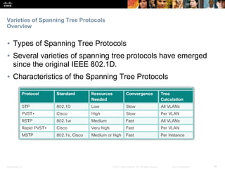
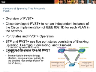
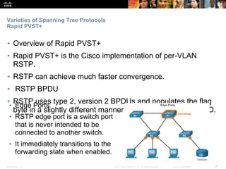
© 2017 Cisco Systems, Inc. All rights reserved. Cisco ConfidentialPresentation_ID 1
Chapter 3: STP
Scaling Networks
Presentation_ID ‹#›© 2017 Cisco Systems, Inc. All rights reserved. Cisco Confidential
Chapter 3- Sections & Objectives
▪ 3.1 Spanning Tree Concepts
▪ Examine the purpose of STP and how the spanning tree
algorithm is used create a loop-free topology.
▪ 3.2 Varieties of Spanning Tree Protocols
▪ Examine the varieties of Spanning Tree protocols including
PVST+ and Rapid PVST+.
▪ 3.3 Spanning Tree Configuration
▪ Configure PVST+ and Rapid PVST+ to improve network
performance.
© 2017 Cisco Systems, Inc. All rights reserved. Cisco ConfidentialPresentation_ID 3
3.1 Spanning Tree
Concepts
Presentation_ID ‹#›© 2017 Cisco Systems, Inc. All rights reserved. Cisco Confidential
Spanning Tree Concepts
Purpose of Spanning Tree
▪ Redundancy at OSI Layers 1 and 2
▪ When multiple paths exist between
two devices on a network, and there
is no spanning tree implementation
on the switches, a Layer 2 loop
occurs.
▪ Issues with Layer 1 Redundancy: MAC Database Instability
▪ Ethernet has no mechanism enabled to block continued propagation of
these frames on a switched network that continue to propagate between
switches.
▪ Issues with Layer 1 Redundancy: Broadcast Storms
▪ A broadcast storm occurs when there are so many broadcast frames
caught in a Layer 2 loop that all available bandwidth is consumed.
Presentation_ID ‹#›© 2017 Cisco Systems, Inc. All rights reserved. Cisco Confidential
Spanning Tree Concepts
Purpose of Spanning Tree
▪ Issues with Layer 1 Redundancy: Duplicate Unicast Frames
▪ An unknown unicast frame is when the switch does not have
the destination MAC address in its MAC address table and
must forward the frame out all ports, except the ingress port.
▪ Unknown unicast frames sent onto a looped network can
result in duplicate frames arriving at the destination device.
Presentation_ID ‹#›© 2017 Cisco Systems, Inc. All rights reserved. Cisco Confidential
Spanning Tree Concepts
STP Operation
▪ Spanning Tree Algorithm: Introduction
▪ STP ensures that there is only one logical path between all
destinations on the network by intentionally blocking redundant
paths that could cause a loop.
▪ Spanning Tree Algorithm: Port Roles
▪ Root ports - Ports closest to the root bridge.
▪ Designated ports - Non-root ports permitted to forward traffic.
▪ Alternate and backup ports - Blocking state to prevent loops.
▪ Disabled ports - A disabled port is a switch port that is shut down.
▪ Spanning Tree Algorithm: Root Bridge
▪ The root bridge serves as a reference point for all STP
calculations.
▪ The switch with the lowest BID will become the root bridge
Presentation_ID ‹#›© 2017 Cisco Systems, Inc. All rights reserved. Cisco Confidential
Spanning Tree Concepts
STP Operation
▪ Spanning Tree Algorithm: Root Path Cost
▪ Default port costs are defined by the speed at which the port operates
▪ Internal root path cost is determined by summing up the individual port
costs along the path from the switch to the root bridge.
▪ Use the spanning-tree cost value interface configuration command on
both ends of a link to apply a custom cost.
▪ Use the show spanning-tree command to verify the port and internal root
path cost to the root bridge.
Presentation_ID ‹#›© 2017 Cisco Systems, Inc. All rights reserved. Cisco Confidential
Spanning Tree Concepts
STP Operation
▪ Port Role Decisions for RSTP
▪ Root bridge automatically configures all of its switch ports in
the designated role.
▪ Designated ports are configured for all LAN segments.
▪ Designated and Alternate Ports
▪ The switch with the lower cost path to the root bridge (root
path cost) will have its port selected as the designated port.
▪ The alternate port will not send or receive traffic on that
segment.
Presentation_ID ‹#›© 2017 Cisco Systems, Inc. All rights reserved. Cisco Confidential
Spanning Tree Concepts
STP Operation
▪ 802.1D BPDU Frame Format
▪ The spanning tree algorithm depends on the exchange of
BPDUs.
▪ The BPDU frame information is included in the Data portion
of an Ethernet frame and identifies the following fields:
Presentation_ID ‹#›© 2017 Cisco Systems, Inc. All rights reserved. Cisco Confidential
Spanning Tree Concepts
STP Operation
▪ 802.1D BPDU Propagation and Process
▪ By default, BPDU frames are sent every two seconds.
▪ Each switch maintains local information about its own BID, the root
ID, and the root path cost.
▪ Extended System ID
▪ The bridge ID (BID) is used to determine the root bridge on a
network. The BID field of a BPDU frame contains three separate
fields:
▪ Bridge priority – Default 32768
▪ Extended system ID - Identifies the VLAN participating in STP
▪ MAC address - When the bridge priorities are equal, the MAC
address is the deciding factor as to which switch is going to
become the root bridge.
© 2017 Cisco Systems, Inc. All rights reserved. Cisco ConfidentialPresentation_ID 11
3.2 Varieties of Spanning
Tree Protocols
Presentation_ID ‹#›© 2017 Cisco Systems, Inc. All rights reserved. Cisco Confidential
Varieties of Spanning Tree Protocols
Overview
▪ Types of Spanning Tree Protocols
▪ Several varieties of spanning tree protocols have emerged
since the original IEEE 802.1D.
▪ Characteristics of the Spanning Tree Protocols
Presentation_ID ‹#›© 2017 Cisco Systems, Inc. All rights reserved. Cisco Confidential
Varieties of Spanning Tree Protocols
PVST+
▪ Overview of PVST+
▪ Cisco developed PVST+ to run an independent instance of
the Cisco implementation of IEEE 802.1D for each VLAN in
the network.
▪ Port States and PVST+ Operation
▪ STP and PVST+ use five port states consisting of Blocking,
Listening, Learning, Forwarding, and Disabled.
▪ Extended System ID and PVST+ Operation
• Extended system ID ensures
switches have unique BIDs for each
VLAN.
• To manipulate the root-bridge
election, assign a lower priority to
the desired root bridge switch for
the VLAN(s).
Presentation_ID ‹#›© 2017 Cisco Systems, Inc. All rights reserved. Cisco Confidential
Varieties of Spanning Tree Protocols
Rapid PVST+
▪ Overview of Rapid PVST+
▪ Rapid PVST+ is the Cisco implementation of per-VLAN
RSTP.
▪ RSTP can achieve much faster convergence.
▪ RSTP BPDU
▪ RSTP uses type 2, version 2 BPDUs and populates the flag
byte in a slightly different manner than in the original 802.1D.
▪ Edge Ports
▪ RSTP edge port is a switch port
that is never intended to be
connected to another switch.
▪ It immediately transitions to the
forwarding state when enabled.
Presentation_ID ‹#›© 2017 Cisco Systems, Inc. All rights reserved. Cisco Confidential
Varieties of Spanning Tree Protocols
Rapid PVST+
▪ Link Types
▪ Point-to-Point - A port operating in full-duplex mode typically
connects a switch to a switch and is a candidate for a rapid
transition to a forwarding state.
▪ Shared - A port operating in half-duplex mode connects a
switch to a legacy hub that attaches multiple devices.• RSTP must determine the port role:
• Root ports and Alternate (backup)
ports do not use the link-type
parameter in most cases.
• Designated ports make the most
use of the link-type parameter and
transition to the forwarding state if
the link-type parameter is set to
point-to-point.
© 2017 Cisco Systems, Inc. All rights reserved. Cisco ConfidentialPresentation_ID 16
3.3 Spanning Tree
Configuration
Presentation_ID ‹#›© 2017 Cisco Systems, Inc. All rights reserved. Cisco Confidential
Spanning Tree Configuration
PVST+ Configuration
▪ Catalyst 2960 Default Configuration
▪ Default spanning tree mode is PVST+.
▪ Configuring and Verifying the Bridge ID
• Method 1:
• Use the spanning-tree vlan
vlan-id root primary global
config command.
• Method 2:
• Use the spanning-tree vlan
vlan-id priority value global
config command.
• Use the show spanning-tree
command to verify the bridge
priority of a switch.
Presentation_ID ‹#›© 2017 Cisco Systems, Inc. All rights reserved. Cisco Confidential
Spanning Tree Configuration
PVST+ Configuration
▪ PortFast and BPDU Guard
▪ PortFast immediately transitions an access port from blocking
to forwarding state while BPDU guard puts an access port in
an errdisabled (error-disabled) state if it receives a BPDU.
▪ Use the spanning-tree portfast interface configuration mode
command to enable PortFast on a switch port.
▪ Use the spanning-tree bpduguard enable interface
configuration mode command to enable BPDU guard on a
Layer 2 access port.
Presentation_ID ‹#›© 2017 Cisco Systems, Inc. All rights reserved. Cisco Confidential
Spanning Tree Configuration
PVST+ Configuration
▪ PVST+ Load Balancing
▪ The goal is to configure two or more root bridges for different
sets of VLANs and make use of redundant links.
S3(config)# spanning-tree vlan 20 root primary
S3(config)# spanning-tree vlan 10 root secondary
S3(config)#
S1(config)# spanning-tree vlan 10 root primary
S1(config)# spanning-tree vlan 20 root secondary
S1(config)#
Presentation_ID ‹#›© 2017 Cisco Systems, Inc. All rights reserved. Cisco Confidential
Spanning Tree Configuration
Rapid PVST+ Configuration
▪ Spanning Tree Mode
▪ Rapid PVST+ is the Cisco implementation of RSTP.
▪ It supports RSTP on a per-VLAN basis.
Presentation_ID ‹#›© 2017 Cisco Systems, Inc. All rights reserved. Cisco Confidential
Spanning Tree Configuration
STP Configuration Issues
▪ Analyzing the STP Topology
▪ Use show cdp neighbors to
discover topology
▪ Use STP knowledge to determine
the root switch
▪ Use show spanning-tree vlan to
verify which switch is the root and
port status (forwarding or
blocking).▪ Expected Topology versus Actual Topology
▪ Troubleshooting consists of comparing the actual state of
the network against the expected state of the network and
spotting the differences.
Presentation_ID ‹#›© 2017 Cisco Systems, Inc. All rights reserved. Cisco Confidential
Spanning Tree Configuration
STP Configuration Issues
▪ Overview of STP Status
▪ Use the show spanning-tree command without specifying any
additional options provides a quick overview of the status of
STP for all VLANs that are defined on a switch.
• Use the show spanning-tree vlan vlan_id command to get STP
information for a particular VLAN.
Presentation_ID ‹#›© 2017 Cisco Systems, Inc. All rights reserved. Cisco Confidential
Spanning Tree Configuration
STP Configuration Issues
▪ Spanning Tree Failure Consequences
▪ There are two types of STP failures:
▪ STP might erroneously block ports that should have gone into the
forwarding state.
▪ STP might erroneously move one or more ports into the forwarding state
▪ Repairing a Spanning Tree Problem
▪ Manually remove redundant links in the switched network, either
physically or through configuration, until all loops are eliminated.
▪ Chances are that restoring the redundant links will trigger a new
broadcast storm.
▪ Before restoring the redundant links, determine and correct the cause of
the spanning tree failure.
▪ Carefully monitor the network to ensure that the problem is fixed.
Presentation_ID ‹#›© 2017 Cisco Systems, Inc. All rights reserved. Cisco Confidential
Spanning Tree Configuration
Switch Stacking Concepts
▪ Switch Stacking Concepts
▪ A switch stack can consist of up to nine Catalyst 3750 switches
connected through their StackWise ports.
▪ One of the switches controls the operation of the stack and is
called the stack master.
▪ The switch is managed as a single switch, through a single IP
address, including passwords, VLANs, and interfaces.
▪ Spanning Tree and Switch Stacks
▪ Another benefit to switch stacking is the ability to add more
switches to a single STP instance without increasing the STP
diameter.
▪ The IEEE recommends a maximum diameter of seven switches
for the default STP timers.
© 2017 Cisco Systems, Inc. All rights reserved. Cisco ConfidentialPresentation_ID 25
3.3 Chapter Summary
Presentation_ID ‹#›© 2017 Cisco Systems, Inc. All rights reserved. Cisco Confidential
▪ Problems that can result from a redundant Layer 2 network include broadcast storms, MAC database
instability, and duplicate unicast frames. STP is a Layer 2 protocol that ensures that there is only one
logical path between all destinations on the network by intentionally blocking redundant paths that could
cause a loop.
▪ STP sends BPDU frames for communication between switches. One switch is elected as the root bridge
for each instance of spanning tree. An administrator can control this election by changing the bridge
priority. Root bridges can be configured to enable spanning tree load balancing by VLAN or by a group
of VLANs, depending on the spanning tree protocol used. STP then assigns a port role to each
participating port using a path cost. The root path cost is equal to the sum of all the port costs along the
path to the root bridge. A port cost is automatically assigned to each port; however, it can also be
manually configured. Paths with the lowest cost become preferred, and all other redundant paths are
blocked.
▪ PVST+ is the default configuration of IEEE 802.1D on Cisco switches. It runs one instance of STP for
each VLAN. A newer, faster-converging spanning tree protocol, RSTP, can be implemented on Cisco
switches on a per-VLAN basis in the form of Rapid PVST+. Multiple Spanning Tree (MST) is the Cisco
implementation of Multiple Spanning Tree Protocol (MSTP), where one instance of spanning tree runs
for a defined group of VLANs. Features such as PortFast and BPDU guard ensure that hosts in the
switched environment are provided immediate access to the network without interfering with spanning
tree operation.
▪ Switch stacking allows connection of up to nine Catalyst 3750 switches to be configured and presented
to the network as a single entity. STP views the switch stack as a single switch. This additional benefit
helps ensure the IEEE recommended maximum diameter of seven switches.
Chapter Summary
Summary
Presentation_ID ‹#›© 2017 Cisco Systems, Inc. All rights reserved. Cisco Confidential

CCNA (R & S) Module 04 - Scaling Networks - Chapter 3

  • 1.
    © 2017 CiscoSystems, Inc. All rights reserved. Cisco ConfidentialPresentation_ID 1 Chapter 3: STP Scaling Networks
  • 2.
    Presentation_ID ‹#›© 2017Cisco Systems, Inc. All rights reserved. Cisco Confidential Chapter 3- Sections & Objectives ▪ 3.1 Spanning Tree Concepts ▪ Examine the purpose of STP and how the spanning tree algorithm is used create a loop-free topology. ▪ 3.2 Varieties of Spanning Tree Protocols ▪ Examine the varieties of Spanning Tree protocols including PVST+ and Rapid PVST+. ▪ 3.3 Spanning Tree Configuration ▪ Configure PVST+ and Rapid PVST+ to improve network performance.
  • 3.
    © 2017 CiscoSystems, Inc. All rights reserved. Cisco ConfidentialPresentation_ID 3 3.1 Spanning Tree Concepts
  • 4.
    Presentation_ID ‹#›© 2017Cisco Systems, Inc. All rights reserved. Cisco Confidential Spanning Tree Concepts Purpose of Spanning Tree ▪ Redundancy at OSI Layers 1 and 2 ▪ When multiple paths exist between two devices on a network, and there is no spanning tree implementation on the switches, a Layer 2 loop occurs. ▪ Issues with Layer 1 Redundancy: MAC Database Instability ▪ Ethernet has no mechanism enabled to block continued propagation of these frames on a switched network that continue to propagate between switches. ▪ Issues with Layer 1 Redundancy: Broadcast Storms ▪ A broadcast storm occurs when there are so many broadcast frames caught in a Layer 2 loop that all available bandwidth is consumed.
  • 5.
    Presentation_ID ‹#›© 2017Cisco Systems, Inc. All rights reserved. Cisco Confidential Spanning Tree Concepts Purpose of Spanning Tree ▪ Issues with Layer 1 Redundancy: Duplicate Unicast Frames ▪ An unknown unicast frame is when the switch does not have the destination MAC address in its MAC address table and must forward the frame out all ports, except the ingress port. ▪ Unknown unicast frames sent onto a looped network can result in duplicate frames arriving at the destination device.
  • 6.
    Presentation_ID ‹#›© 2017Cisco Systems, Inc. All rights reserved. Cisco Confidential Spanning Tree Concepts STP Operation ▪ Spanning Tree Algorithm: Introduction ▪ STP ensures that there is only one logical path between all destinations on the network by intentionally blocking redundant paths that could cause a loop. ▪ Spanning Tree Algorithm: Port Roles ▪ Root ports - Ports closest to the root bridge. ▪ Designated ports - Non-root ports permitted to forward traffic. ▪ Alternate and backup ports - Blocking state to prevent loops. ▪ Disabled ports - A disabled port is a switch port that is shut down. ▪ Spanning Tree Algorithm: Root Bridge ▪ The root bridge serves as a reference point for all STP calculations. ▪ The switch with the lowest BID will become the root bridge
  • 7.
    Presentation_ID ‹#›© 2017Cisco Systems, Inc. All rights reserved. Cisco Confidential Spanning Tree Concepts STP Operation ▪ Spanning Tree Algorithm: Root Path Cost ▪ Default port costs are defined by the speed at which the port operates ▪ Internal root path cost is determined by summing up the individual port costs along the path from the switch to the root bridge. ▪ Use the spanning-tree cost value interface configuration command on both ends of a link to apply a custom cost. ▪ Use the show spanning-tree command to verify the port and internal root path cost to the root bridge.
  • 8.
    Presentation_ID ‹#›© 2017Cisco Systems, Inc. All rights reserved. Cisco Confidential Spanning Tree Concepts STP Operation ▪ Port Role Decisions for RSTP ▪ Root bridge automatically configures all of its switch ports in the designated role. ▪ Designated ports are configured for all LAN segments. ▪ Designated and Alternate Ports ▪ The switch with the lower cost path to the root bridge (root path cost) will have its port selected as the designated port. ▪ The alternate port will not send or receive traffic on that segment.
  • 9.
    Presentation_ID ‹#›© 2017Cisco Systems, Inc. All rights reserved. Cisco Confidential Spanning Tree Concepts STP Operation ▪ 802.1D BPDU Frame Format ▪ The spanning tree algorithm depends on the exchange of BPDUs. ▪ The BPDU frame information is included in the Data portion of an Ethernet frame and identifies the following fields:
  • 10.
    Presentation_ID ‹#›© 2017Cisco Systems, Inc. All rights reserved. Cisco Confidential Spanning Tree Concepts STP Operation ▪ 802.1D BPDU Propagation and Process ▪ By default, BPDU frames are sent every two seconds. ▪ Each switch maintains local information about its own BID, the root ID, and the root path cost. ▪ Extended System ID ▪ The bridge ID (BID) is used to determine the root bridge on a network. The BID field of a BPDU frame contains three separate fields: ▪ Bridge priority – Default 32768 ▪ Extended system ID - Identifies the VLAN participating in STP ▪ MAC address - When the bridge priorities are equal, the MAC address is the deciding factor as to which switch is going to become the root bridge.
  • 11.
    © 2017 CiscoSystems, Inc. All rights reserved. Cisco ConfidentialPresentation_ID 11 3.2 Varieties of Spanning Tree Protocols
  • 12.
    Presentation_ID ‹#›© 2017Cisco Systems, Inc. All rights reserved. Cisco Confidential Varieties of Spanning Tree Protocols Overview ▪ Types of Spanning Tree Protocols ▪ Several varieties of spanning tree protocols have emerged since the original IEEE 802.1D. ▪ Characteristics of the Spanning Tree Protocols
  • 13.
    Presentation_ID ‹#›© 2017Cisco Systems, Inc. All rights reserved. Cisco Confidential Varieties of Spanning Tree Protocols PVST+ ▪ Overview of PVST+ ▪ Cisco developed PVST+ to run an independent instance of the Cisco implementation of IEEE 802.1D for each VLAN in the network. ▪ Port States and PVST+ Operation ▪ STP and PVST+ use five port states consisting of Blocking, Listening, Learning, Forwarding, and Disabled. ▪ Extended System ID and PVST+ Operation • Extended system ID ensures switches have unique BIDs for each VLAN. • To manipulate the root-bridge election, assign a lower priority to the desired root bridge switch for the VLAN(s).
  • 14.
    Presentation_ID ‹#›© 2017Cisco Systems, Inc. All rights reserved. Cisco Confidential Varieties of Spanning Tree Protocols Rapid PVST+ ▪ Overview of Rapid PVST+ ▪ Rapid PVST+ is the Cisco implementation of per-VLAN RSTP. ▪ RSTP can achieve much faster convergence. ▪ RSTP BPDU ▪ RSTP uses type 2, version 2 BPDUs and populates the flag byte in a slightly different manner than in the original 802.1D. ▪ Edge Ports ▪ RSTP edge port is a switch port that is never intended to be connected to another switch. ▪ It immediately transitions to the forwarding state when enabled.
  • 15.
    Presentation_ID ‹#›© 2017Cisco Systems, Inc. All rights reserved. Cisco Confidential Varieties of Spanning Tree Protocols Rapid PVST+ ▪ Link Types ▪ Point-to-Point - A port operating in full-duplex mode typically connects a switch to a switch and is a candidate for a rapid transition to a forwarding state. ▪ Shared - A port operating in half-duplex mode connects a switch to a legacy hub that attaches multiple devices.• RSTP must determine the port role: • Root ports and Alternate (backup) ports do not use the link-type parameter in most cases. • Designated ports make the most use of the link-type parameter and transition to the forwarding state if the link-type parameter is set to point-to-point.
  • 16.
    © 2017 CiscoSystems, Inc. All rights reserved. Cisco ConfidentialPresentation_ID 16 3.3 Spanning Tree Configuration
  • 17.
    Presentation_ID ‹#›© 2017Cisco Systems, Inc. All rights reserved. Cisco Confidential Spanning Tree Configuration PVST+ Configuration ▪ Catalyst 2960 Default Configuration ▪ Default spanning tree mode is PVST+. ▪ Configuring and Verifying the Bridge ID • Method 1: • Use the spanning-tree vlan vlan-id root primary global config command. • Method 2: • Use the spanning-tree vlan vlan-id priority value global config command. • Use the show spanning-tree command to verify the bridge priority of a switch.
  • 18.
    Presentation_ID ‹#›© 2017Cisco Systems, Inc. All rights reserved. Cisco Confidential Spanning Tree Configuration PVST+ Configuration ▪ PortFast and BPDU Guard ▪ PortFast immediately transitions an access port from blocking to forwarding state while BPDU guard puts an access port in an errdisabled (error-disabled) state if it receives a BPDU. ▪ Use the spanning-tree portfast interface configuration mode command to enable PortFast on a switch port. ▪ Use the spanning-tree bpduguard enable interface configuration mode command to enable BPDU guard on a Layer 2 access port.
  • 19.
    Presentation_ID ‹#›© 2017Cisco Systems, Inc. All rights reserved. Cisco Confidential Spanning Tree Configuration PVST+ Configuration ▪ PVST+ Load Balancing ▪ The goal is to configure two or more root bridges for different sets of VLANs and make use of redundant links. S3(config)# spanning-tree vlan 20 root primary S3(config)# spanning-tree vlan 10 root secondary S3(config)# S1(config)# spanning-tree vlan 10 root primary S1(config)# spanning-tree vlan 20 root secondary S1(config)#
  • 20.
    Presentation_ID ‹#›© 2017Cisco Systems, Inc. All rights reserved. Cisco Confidential Spanning Tree Configuration Rapid PVST+ Configuration ▪ Spanning Tree Mode ▪ Rapid PVST+ is the Cisco implementation of RSTP. ▪ It supports RSTP on a per-VLAN basis.
  • 21.
    Presentation_ID ‹#›© 2017Cisco Systems, Inc. All rights reserved. Cisco Confidential Spanning Tree Configuration STP Configuration Issues ▪ Analyzing the STP Topology ▪ Use show cdp neighbors to discover topology ▪ Use STP knowledge to determine the root switch ▪ Use show spanning-tree vlan to verify which switch is the root and port status (forwarding or blocking).▪ Expected Topology versus Actual Topology ▪ Troubleshooting consists of comparing the actual state of the network against the expected state of the network and spotting the differences.
  • 22.
    Presentation_ID ‹#›© 2017Cisco Systems, Inc. All rights reserved. Cisco Confidential Spanning Tree Configuration STP Configuration Issues ▪ Overview of STP Status ▪ Use the show spanning-tree command without specifying any additional options provides a quick overview of the status of STP for all VLANs that are defined on a switch. • Use the show spanning-tree vlan vlan_id command to get STP information for a particular VLAN.
  • 23.
    Presentation_ID ‹#›© 2017Cisco Systems, Inc. All rights reserved. Cisco Confidential Spanning Tree Configuration STP Configuration Issues ▪ Spanning Tree Failure Consequences ▪ There are two types of STP failures: ▪ STP might erroneously block ports that should have gone into the forwarding state. ▪ STP might erroneously move one or more ports into the forwarding state ▪ Repairing a Spanning Tree Problem ▪ Manually remove redundant links in the switched network, either physically or through configuration, until all loops are eliminated. ▪ Chances are that restoring the redundant links will trigger a new broadcast storm. ▪ Before restoring the redundant links, determine and correct the cause of the spanning tree failure. ▪ Carefully monitor the network to ensure that the problem is fixed.
  • 24.
    Presentation_ID ‹#›© 2017Cisco Systems, Inc. All rights reserved. Cisco Confidential Spanning Tree Configuration Switch Stacking Concepts ▪ Switch Stacking Concepts ▪ A switch stack can consist of up to nine Catalyst 3750 switches connected through their StackWise ports. ▪ One of the switches controls the operation of the stack and is called the stack master. ▪ The switch is managed as a single switch, through a single IP address, including passwords, VLANs, and interfaces. ▪ Spanning Tree and Switch Stacks ▪ Another benefit to switch stacking is the ability to add more switches to a single STP instance without increasing the STP diameter. ▪ The IEEE recommends a maximum diameter of seven switches for the default STP timers.
  • 25.
    © 2017 CiscoSystems, Inc. All rights reserved. Cisco ConfidentialPresentation_ID 25 3.3 Chapter Summary
  • 26.
    Presentation_ID ‹#›© 2017Cisco Systems, Inc. All rights reserved. Cisco Confidential ▪ Problems that can result from a redundant Layer 2 network include broadcast storms, MAC database instability, and duplicate unicast frames. STP is a Layer 2 protocol that ensures that there is only one logical path between all destinations on the network by intentionally blocking redundant paths that could cause a loop. ▪ STP sends BPDU frames for communication between switches. One switch is elected as the root bridge for each instance of spanning tree. An administrator can control this election by changing the bridge priority. Root bridges can be configured to enable spanning tree load balancing by VLAN or by a group of VLANs, depending on the spanning tree protocol used. STP then assigns a port role to each participating port using a path cost. The root path cost is equal to the sum of all the port costs along the path to the root bridge. A port cost is automatically assigned to each port; however, it can also be manually configured. Paths with the lowest cost become preferred, and all other redundant paths are blocked. ▪ PVST+ is the default configuration of IEEE 802.1D on Cisco switches. It runs one instance of STP for each VLAN. A newer, faster-converging spanning tree protocol, RSTP, can be implemented on Cisco switches on a per-VLAN basis in the form of Rapid PVST+. Multiple Spanning Tree (MST) is the Cisco implementation of Multiple Spanning Tree Protocol (MSTP), where one instance of spanning tree runs for a defined group of VLANs. Features such as PortFast and BPDU guard ensure that hosts in the switched environment are provided immediate access to the network without interfering with spanning tree operation. ▪ Switch stacking allows connection of up to nine Catalyst 3750 switches to be configured and presented to the network as a single entity. STP views the switch stack as a single switch. This additional benefit helps ensure the IEEE recommended maximum diameter of seven switches. Chapter Summary Summary
  • 27.
    Presentation_ID ‹#›© 2017Cisco Systems, Inc. All rights reserved. Cisco Confidential