
Downloaded 108 times


![WIS5-90516b
Appendix 3 Pipe Reports and Questions A3-6 Copyright © TWI Ltd
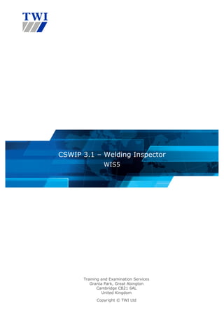
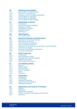
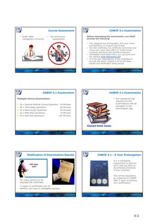
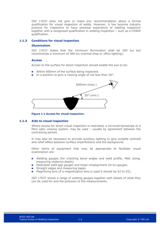
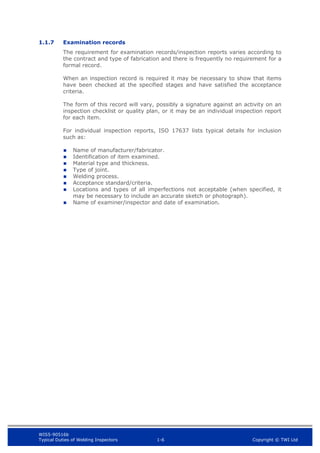
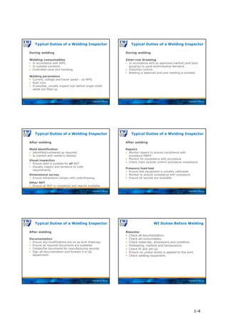
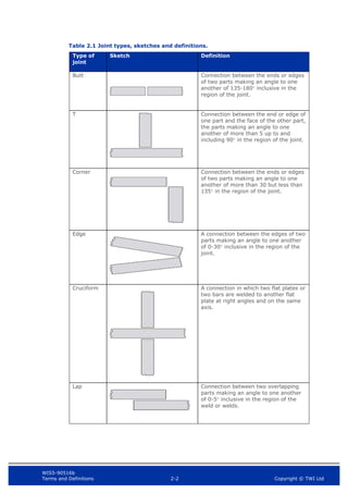
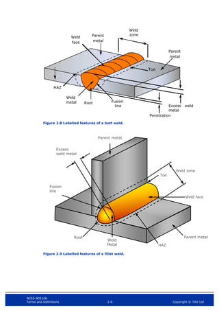
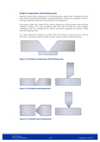
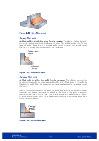
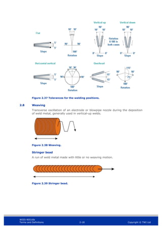
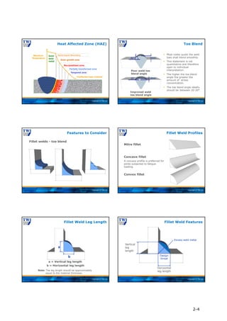
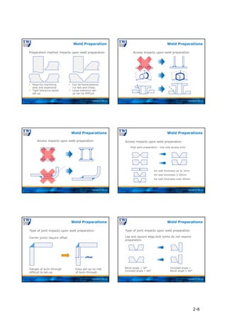
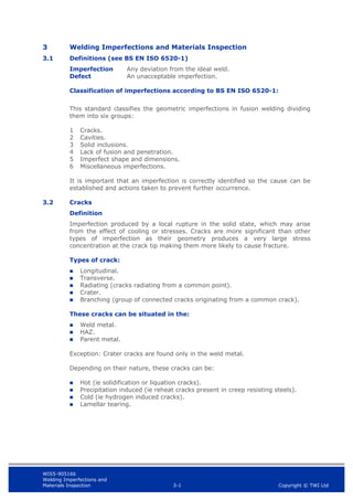
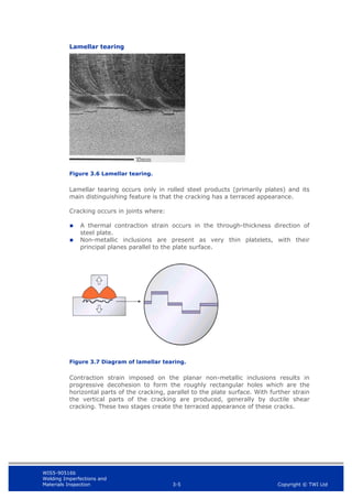
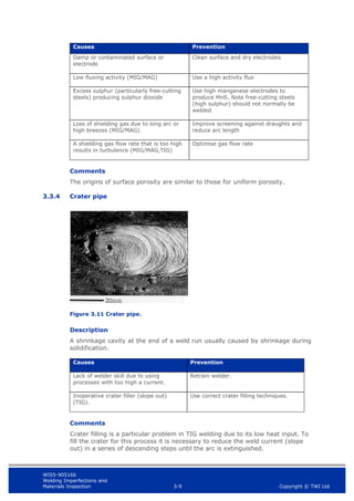
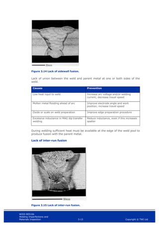
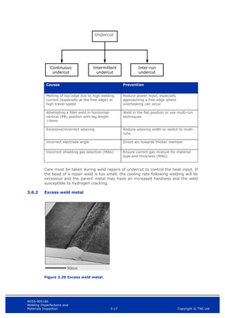
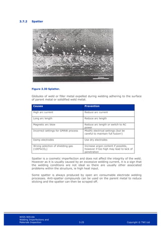
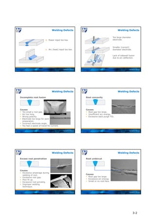
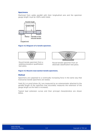
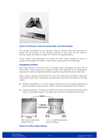
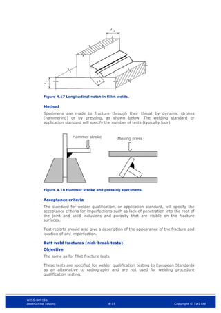
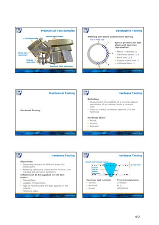
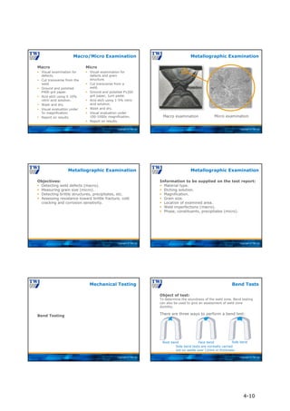
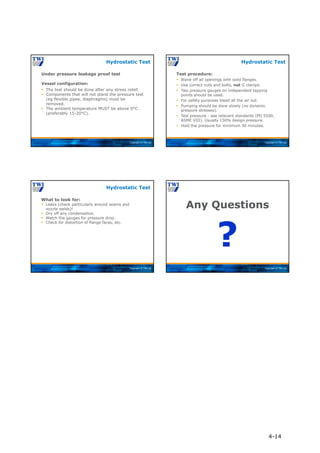
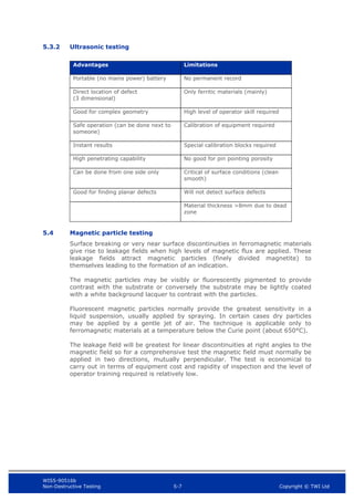
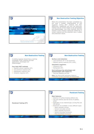
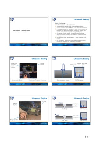
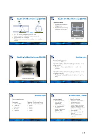
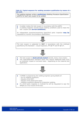
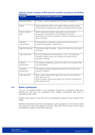
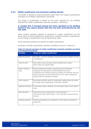
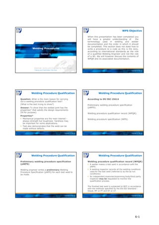
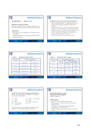
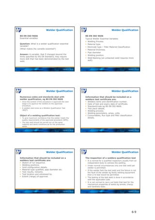
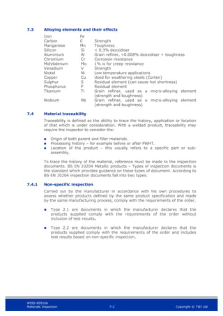
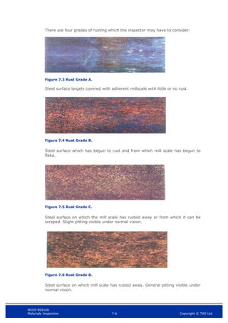
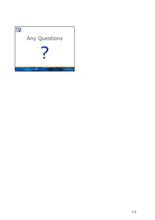
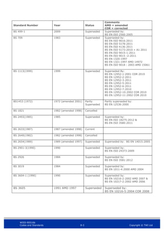
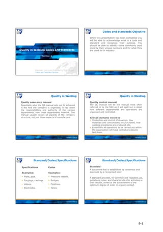
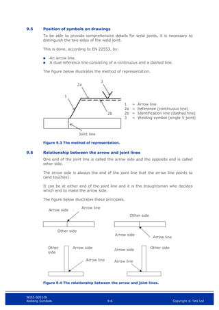
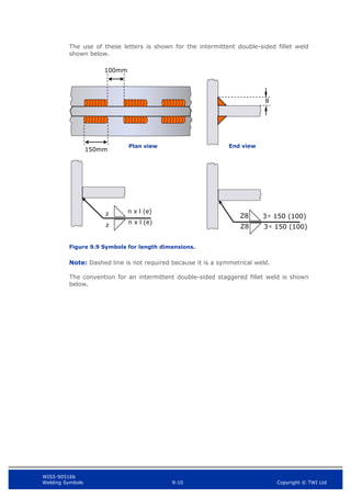
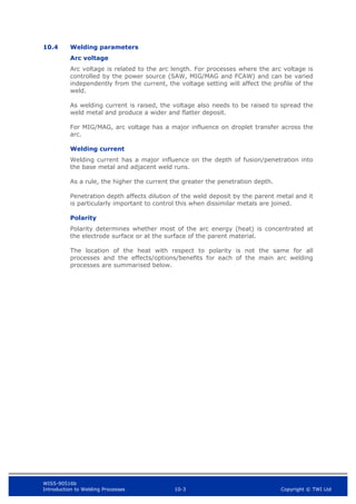
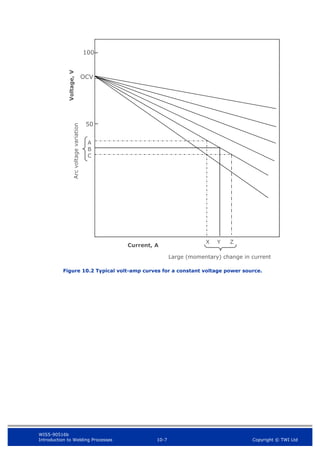
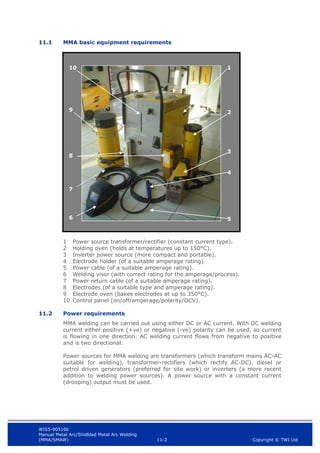
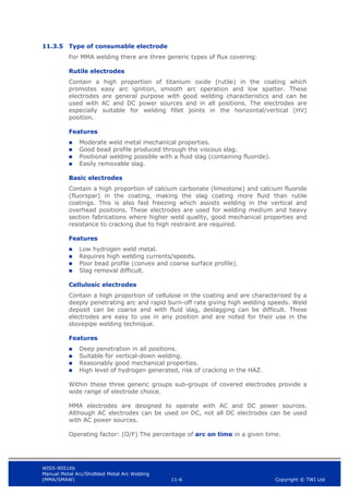
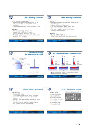
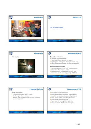
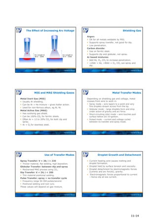
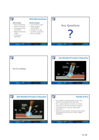
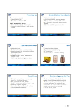
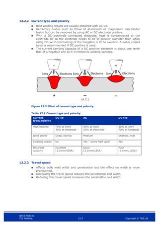
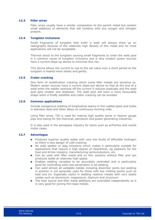
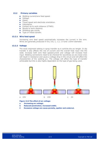
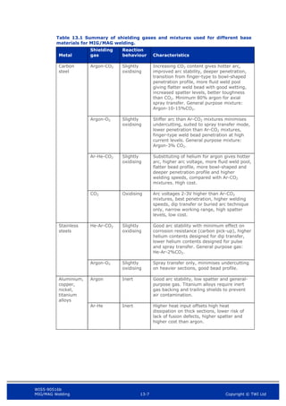
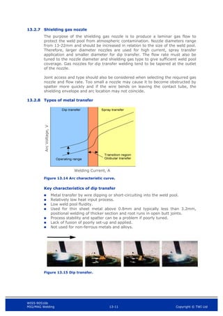
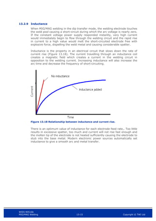
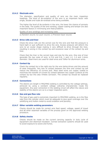
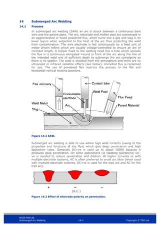
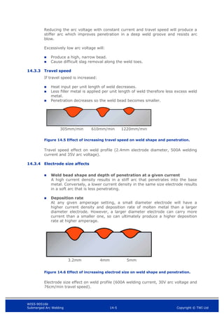
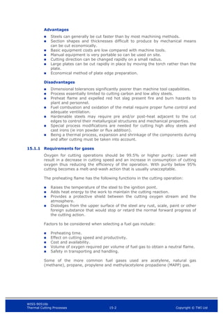
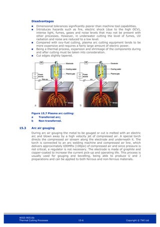
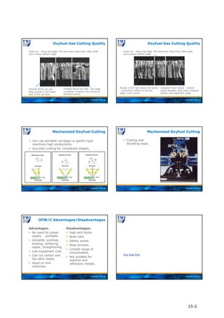
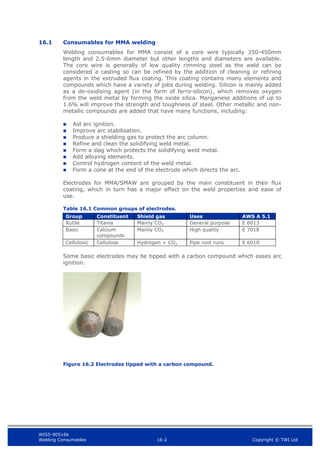
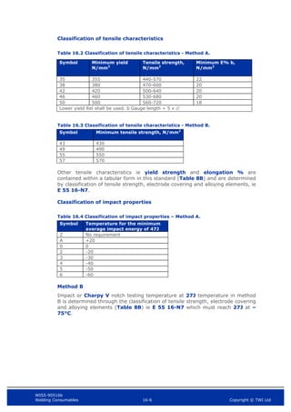
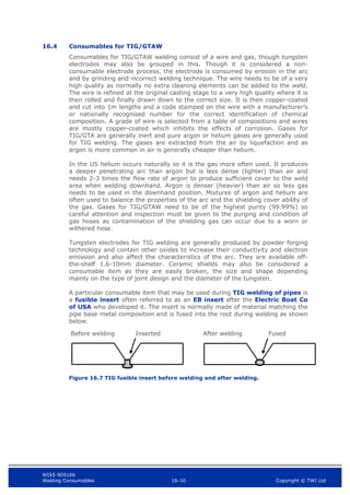
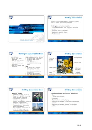
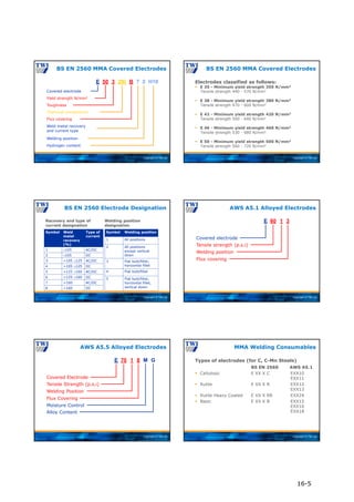
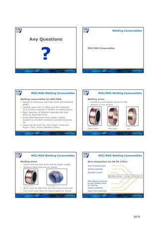
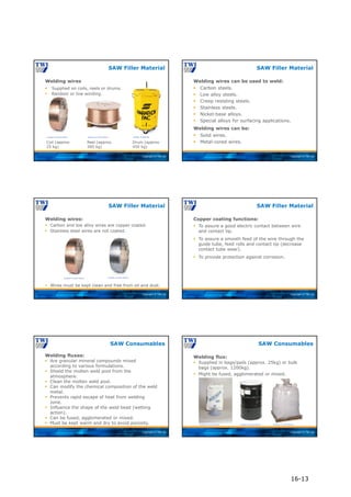
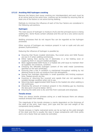
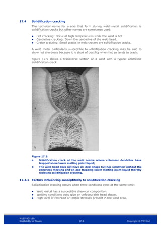
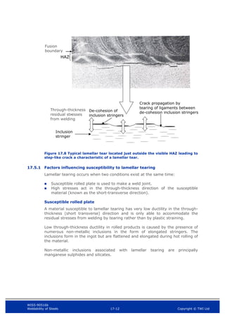
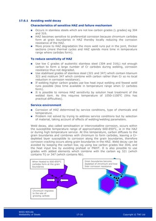
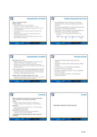
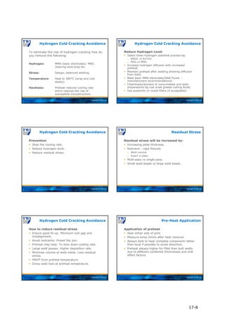
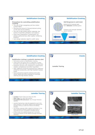
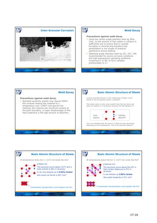
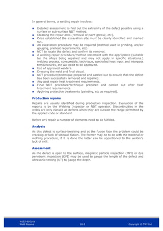
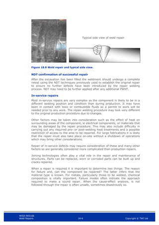
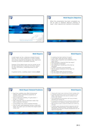
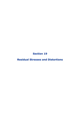
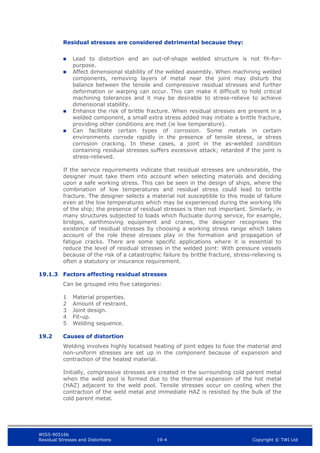
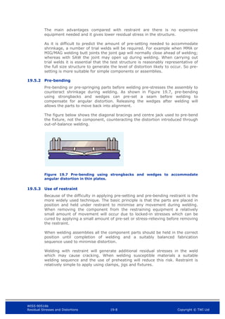
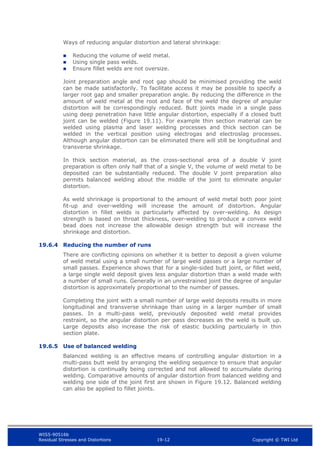
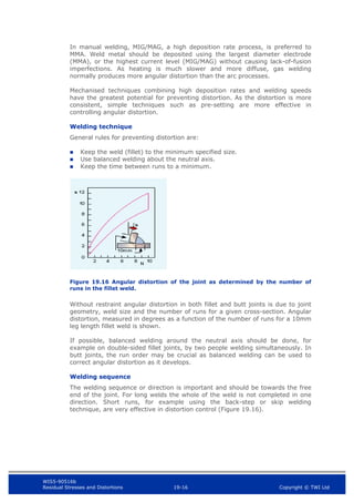
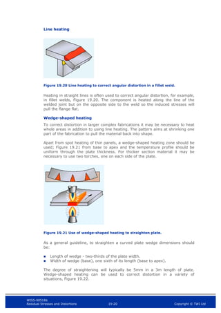
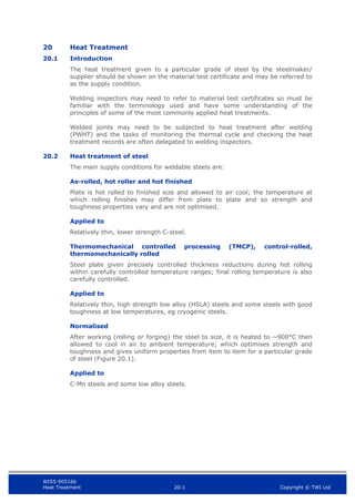
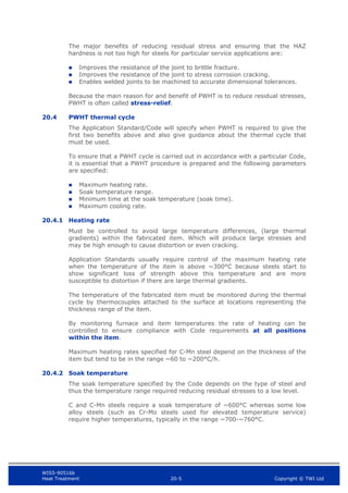
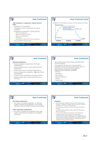
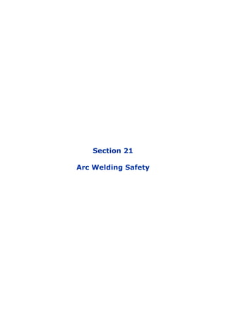
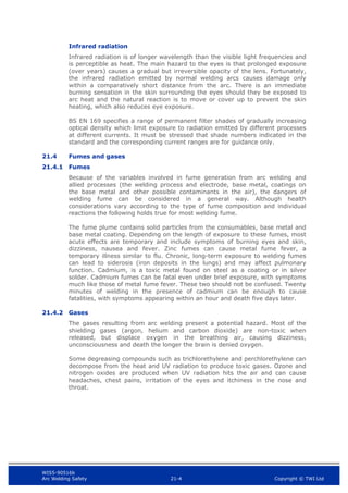
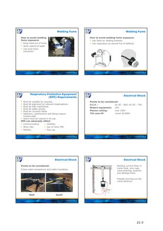
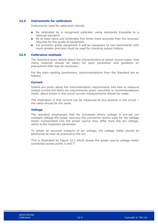
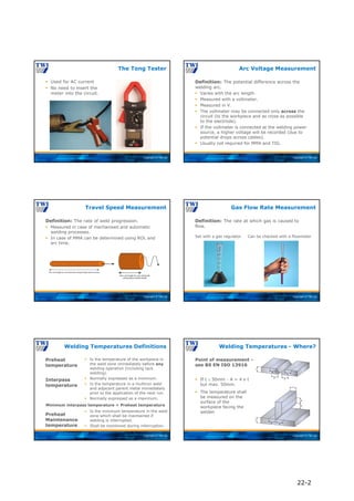
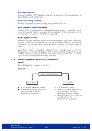
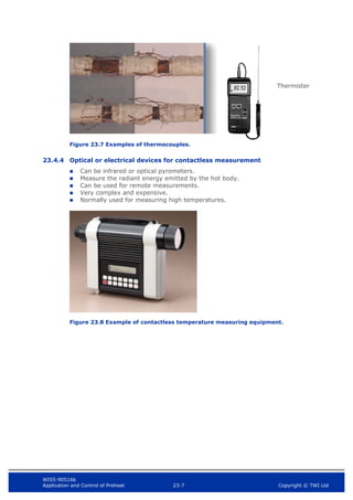
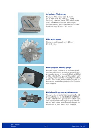
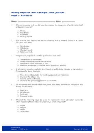
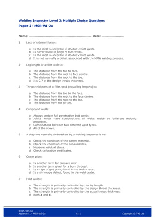
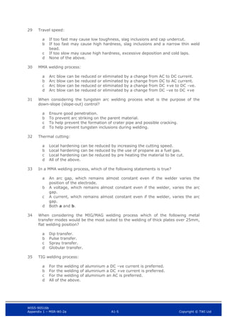
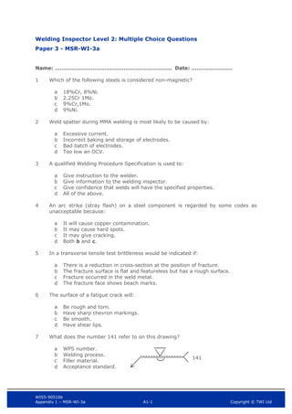
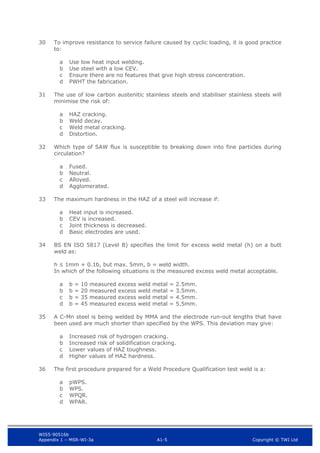
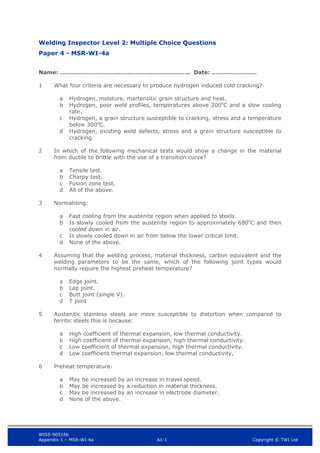
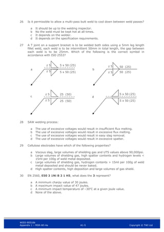
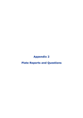
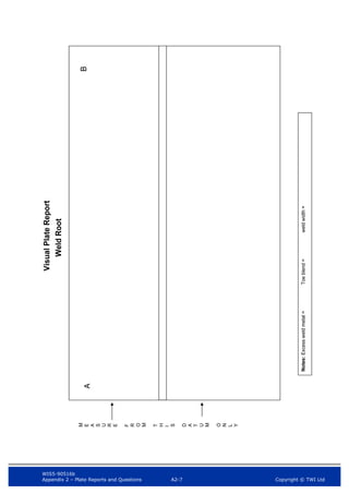
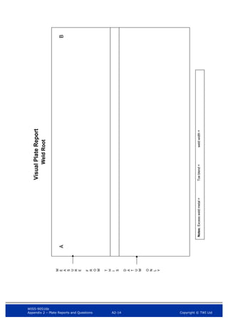
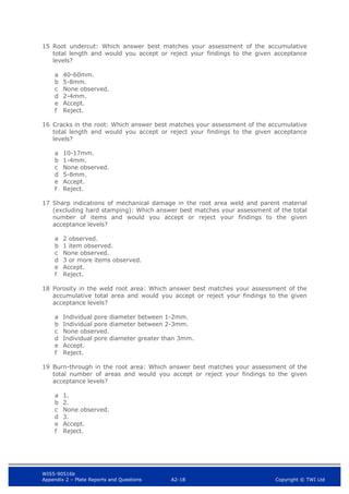
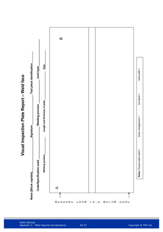
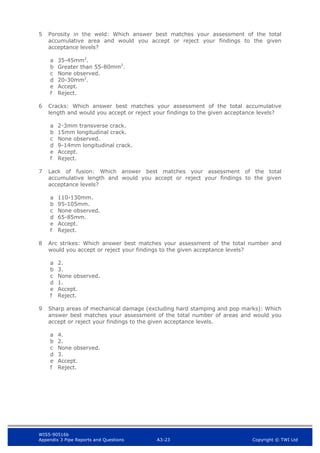
Visual Inspection Pipe Report
Name [Block capitals]
Signature Pipe Ident#
Code/Specification used Welding Process Joint type
Welding position OutsideØ and Thickness Date
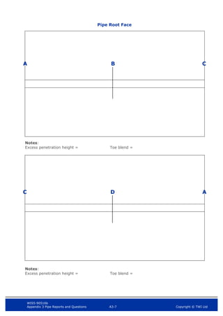
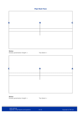
Weld face
A B
C D
Notes:
Excess weld metal height = Misalignment = Weld width = Toe blend =
Notes:
Excess weld metal height = Misalignment = Toe blend = Weld width =
A
C](https://image.slidesharecdn.com/mainbookcswip31weldinginspectorwi-221218121938-b54ec8e9/85/Main_book_CSWIP_3_1_Welding_Inspector_WI-pdf-607-320.jpg)


![WIS5-90516b
Appendix 3 Pipe Reports and Questions A3-13 Copyright © TWI Ltd
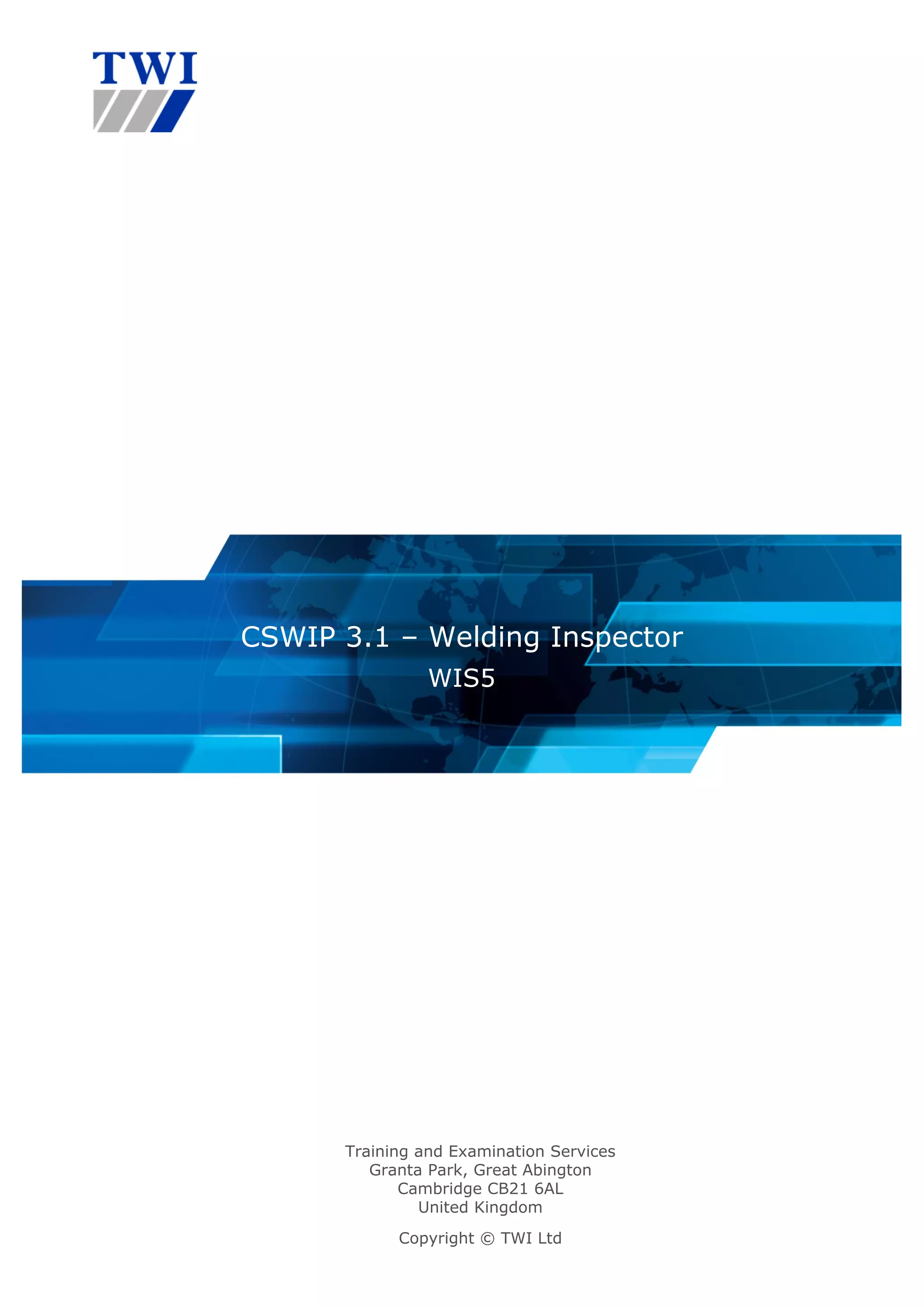
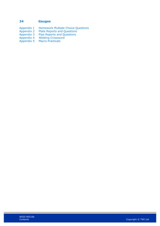
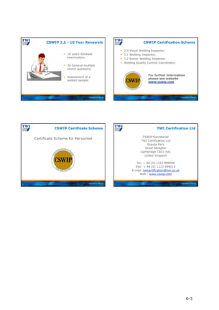
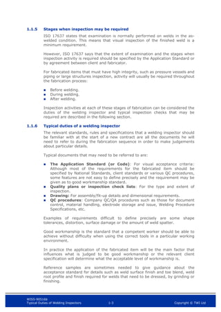
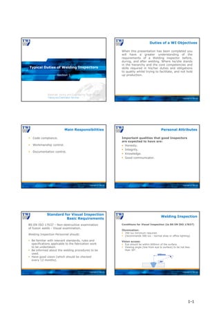
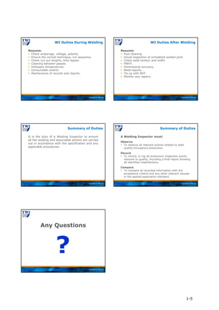
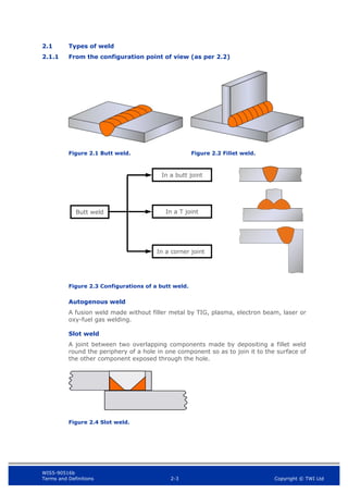
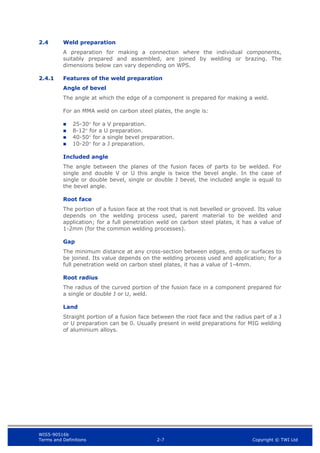
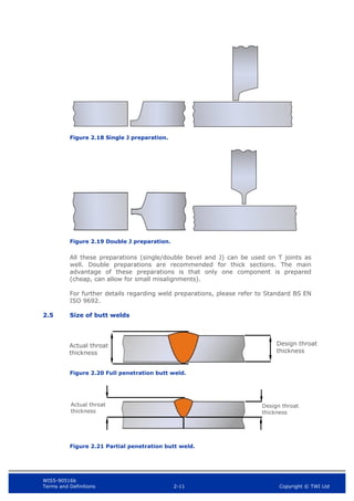
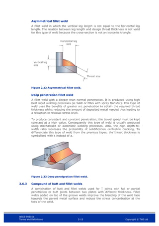
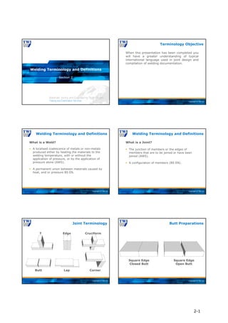
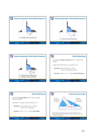
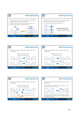
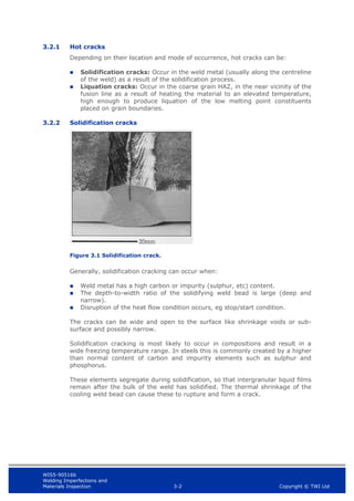
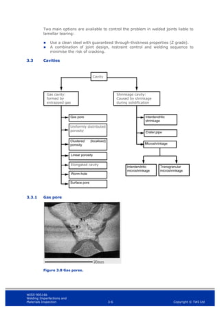
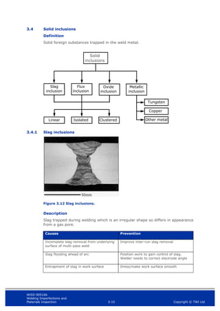
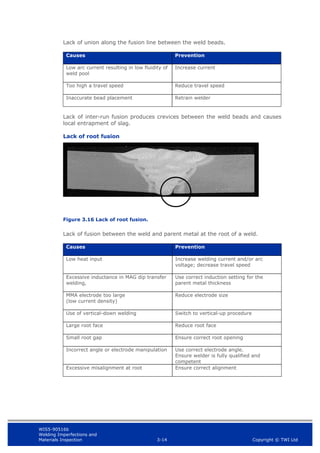
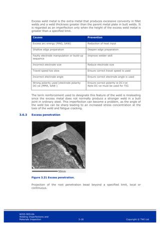
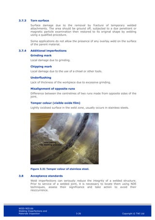
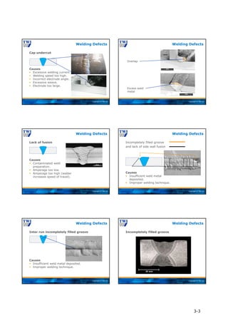
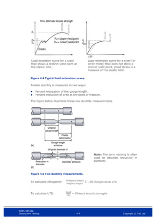
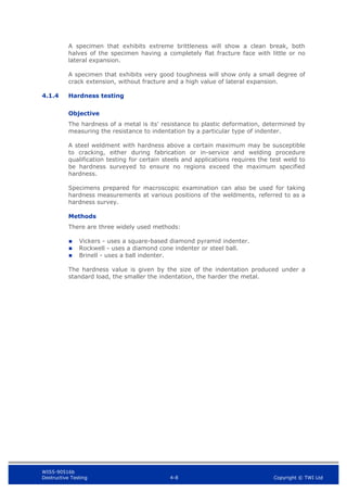
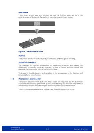
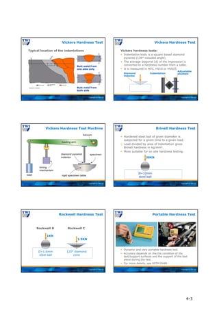
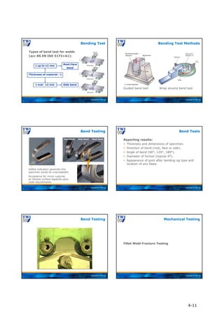
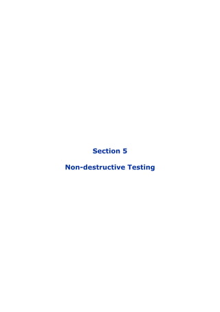
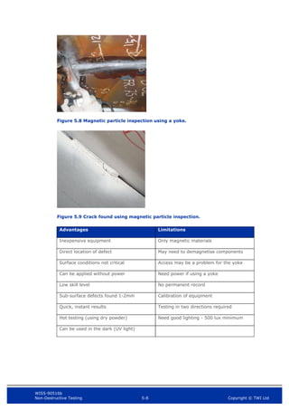
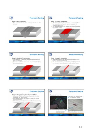
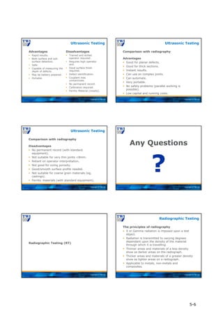
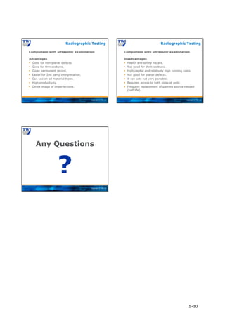
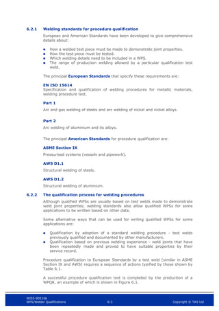
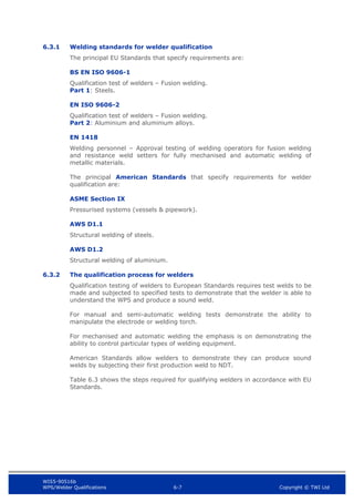
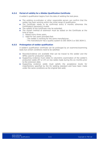
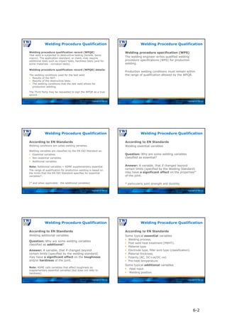
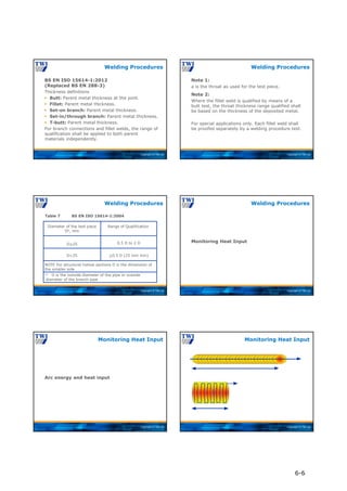
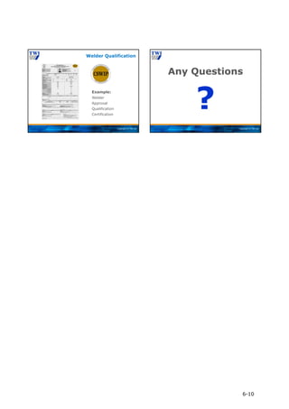
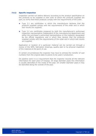
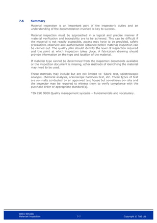
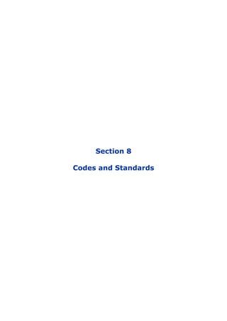
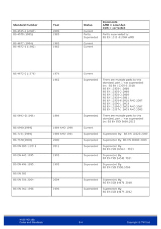
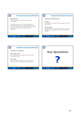
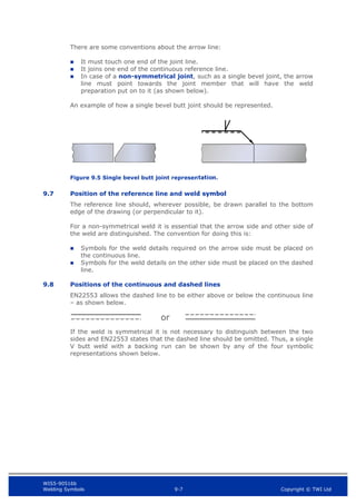
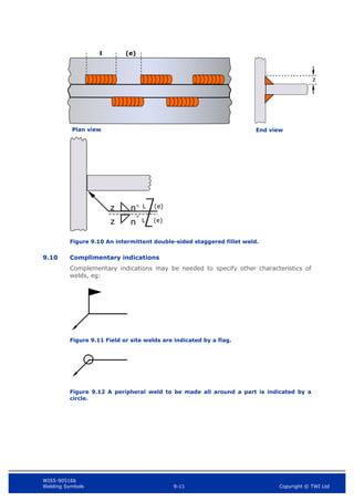
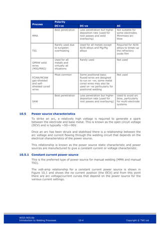
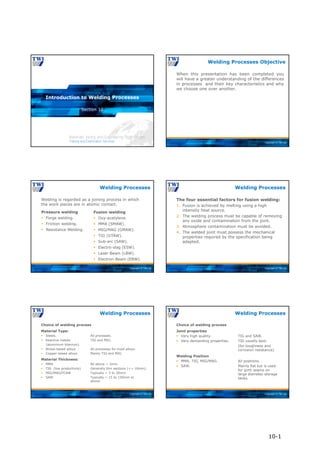
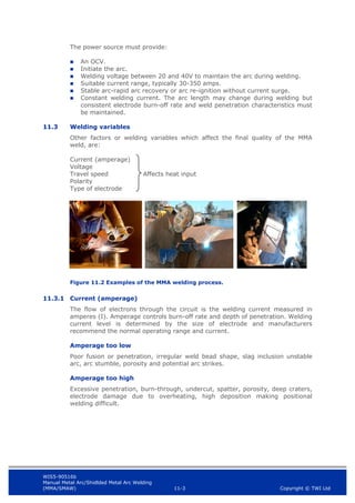
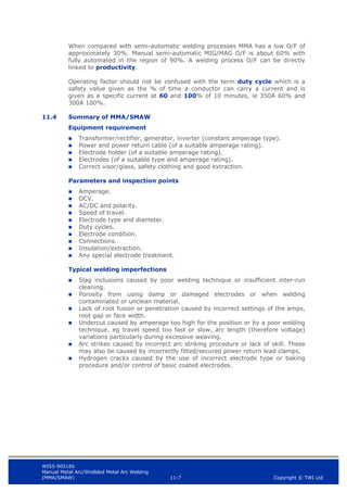
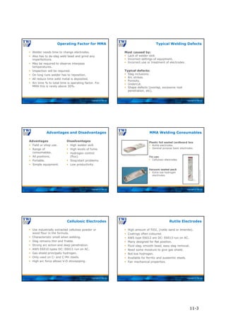
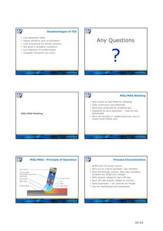
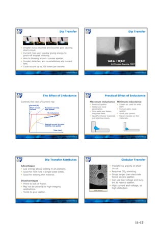
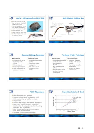
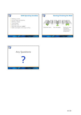
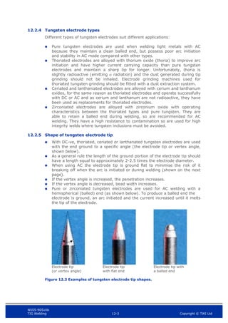
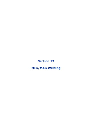
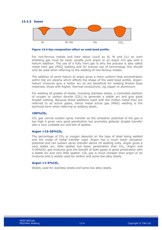
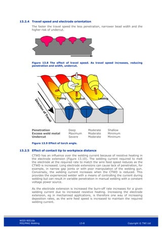
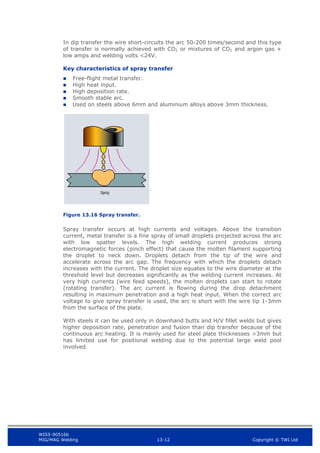
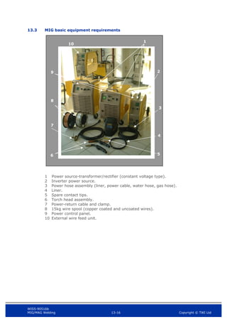
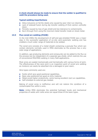
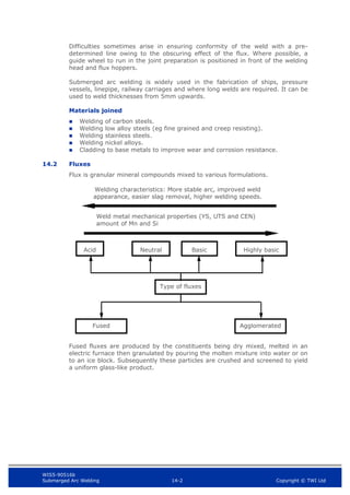
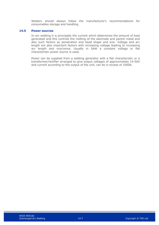
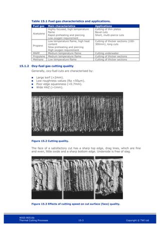
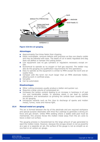
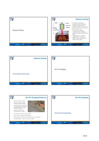
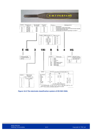
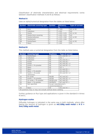
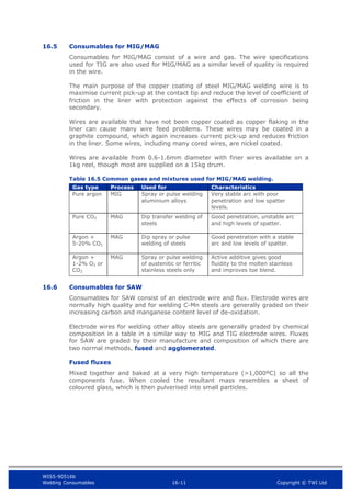
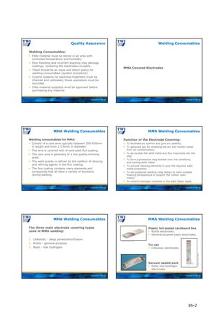
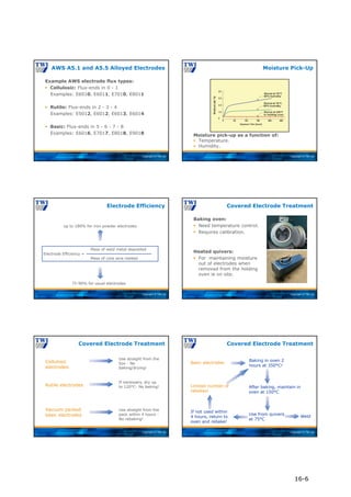
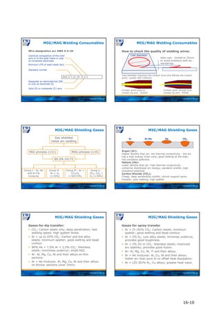
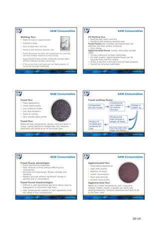
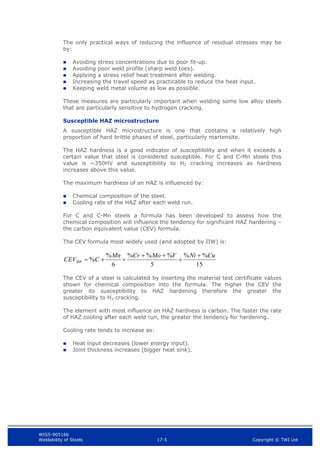
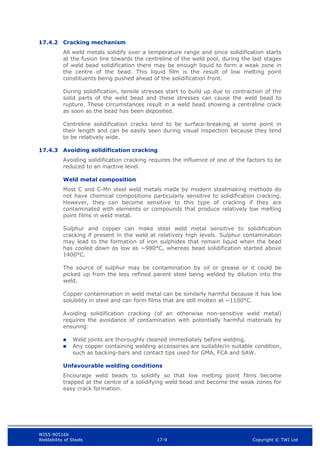
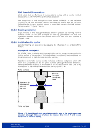
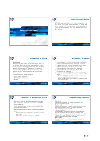
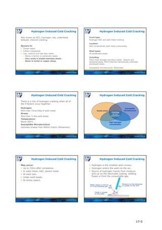
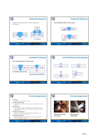
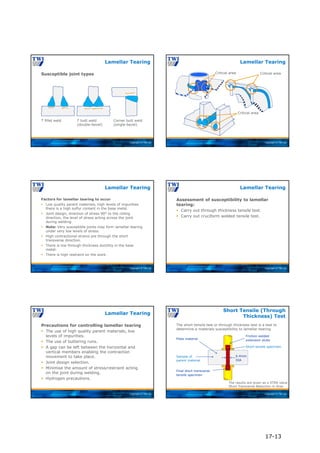
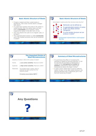
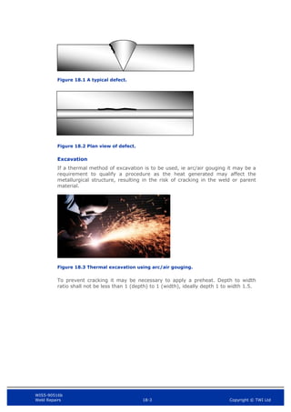
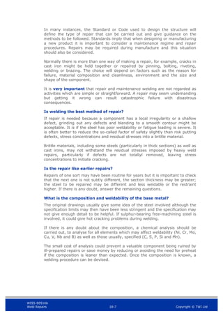
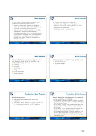
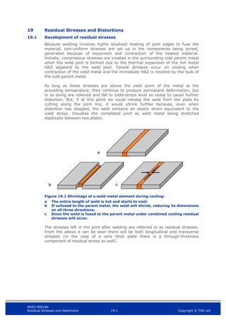
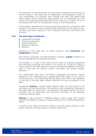
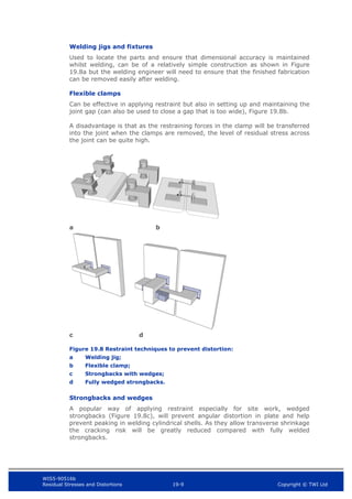
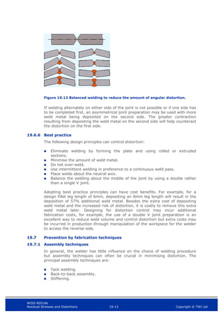
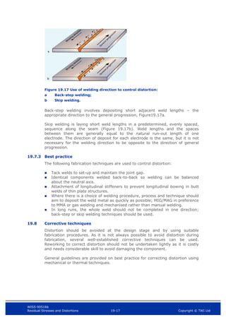
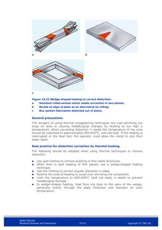
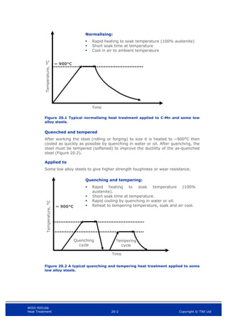
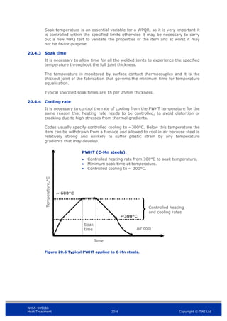
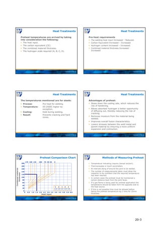
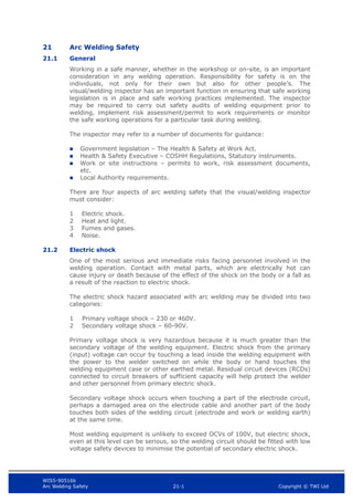
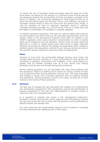
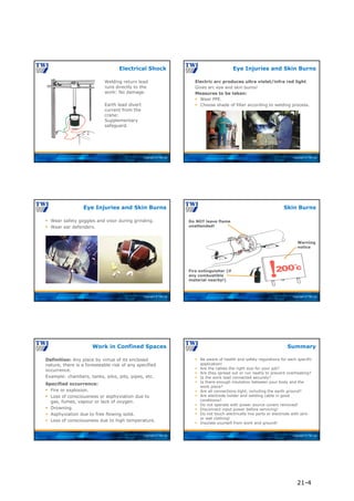
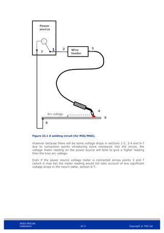
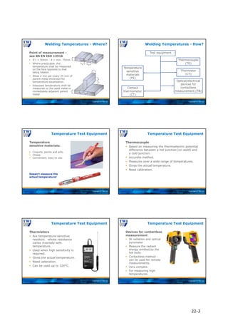
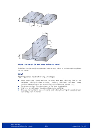
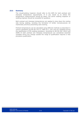
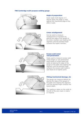
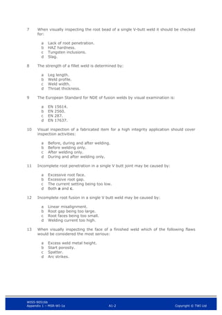
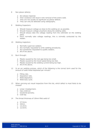
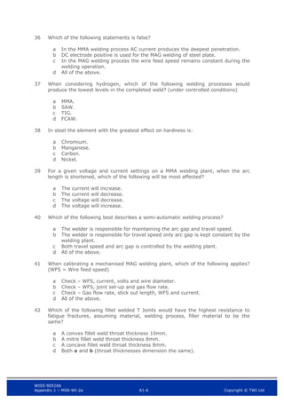
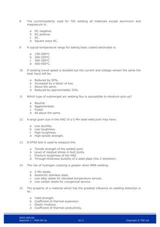
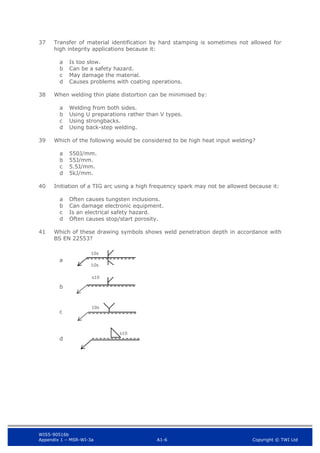
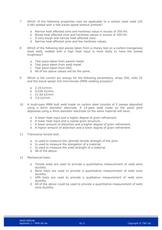
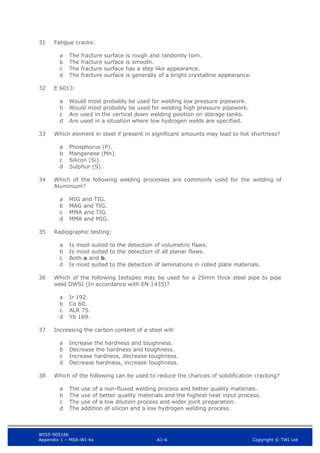
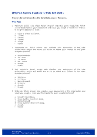
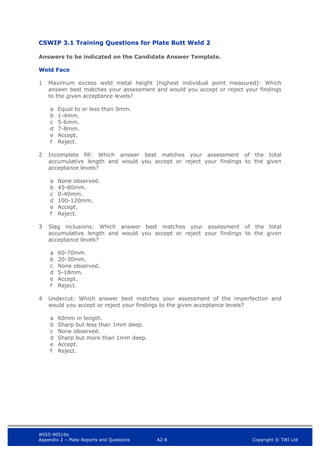
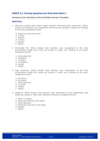
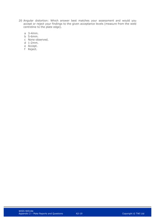
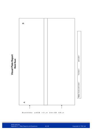
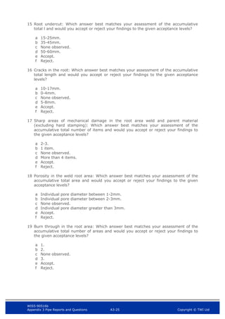
Visual Inspection Pipe Report
Name [Block capitals]
Signature Pipe Ident#
Code/Specification used Welding Process Joint type
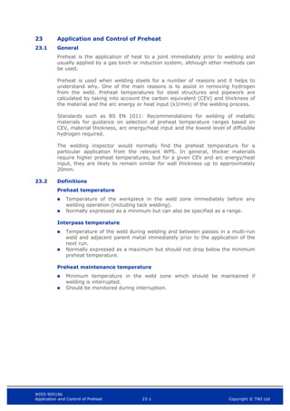
Welding position OutsideØ and Thickness Date
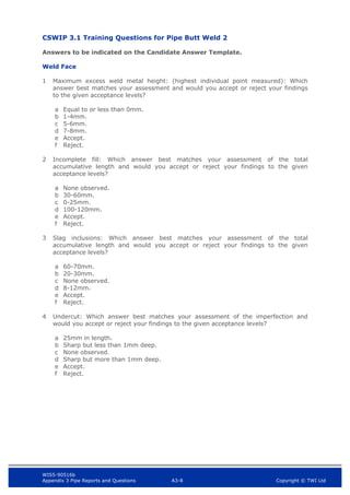
Weld face
A B
C D
Notes:
Excess weld metal height = Misalignment = Weld width = Toe blend =
Notes:
Excess weld metal height = Misalignment = Toe blend = Weld width =
A
C](https://image.slidesharecdn.com/mainbookcswip31weldinginspectorwi-221218121938-b54ec8e9/85/Main_book_CSWIP_3_1_Welding_Inspector_WI-pdf-619-320.jpg)


![WIS5-90516b
Appendix 3 Pipe Reports and Questions A3-20 Copyright © TWI Ltd
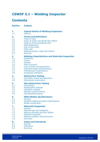
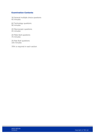
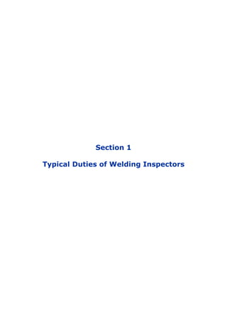
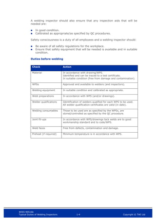
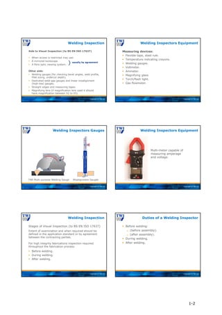
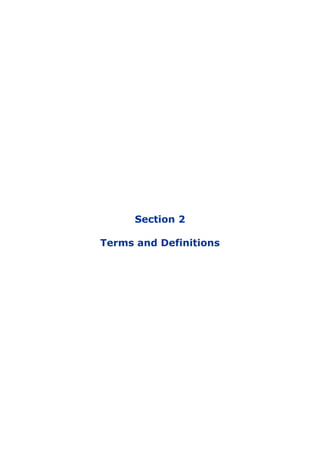
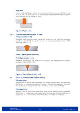
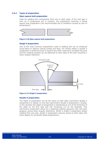
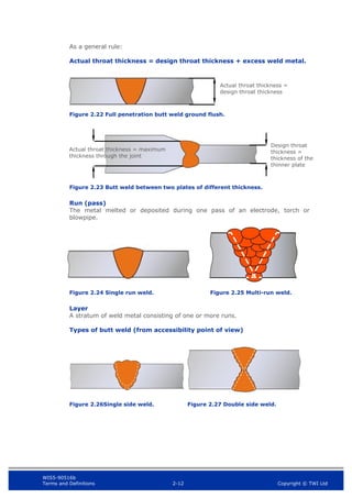
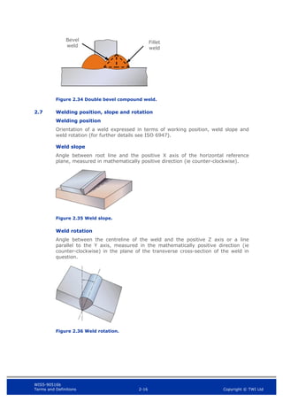
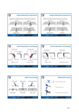
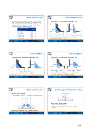
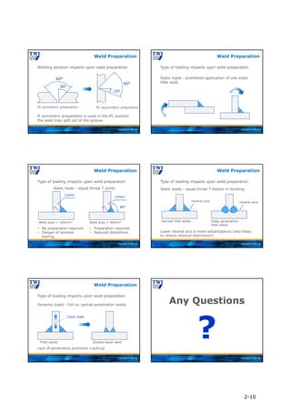
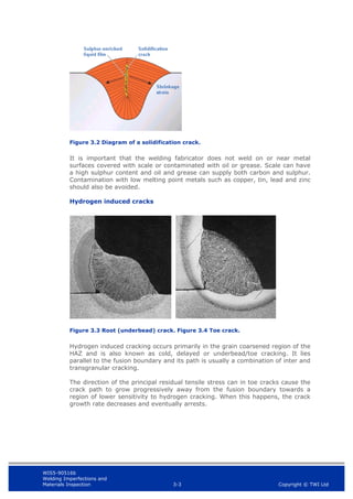
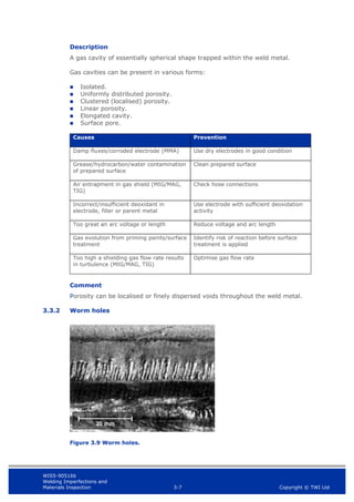
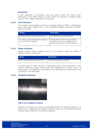
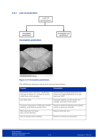
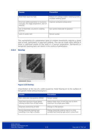
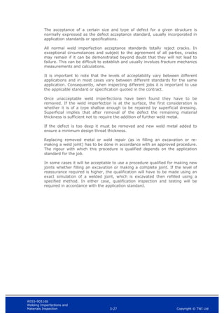
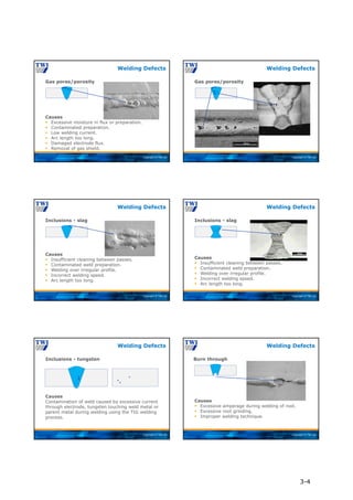
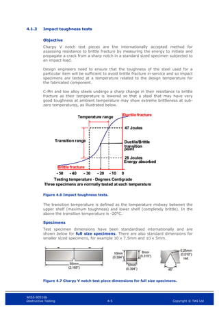
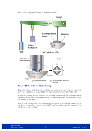
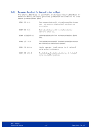
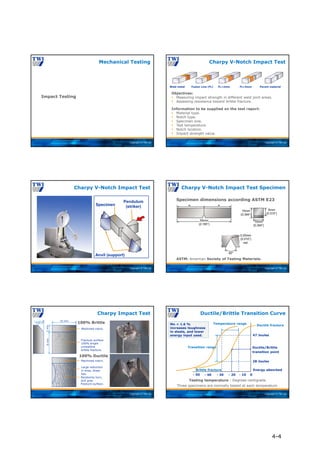
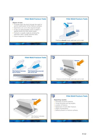
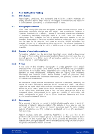
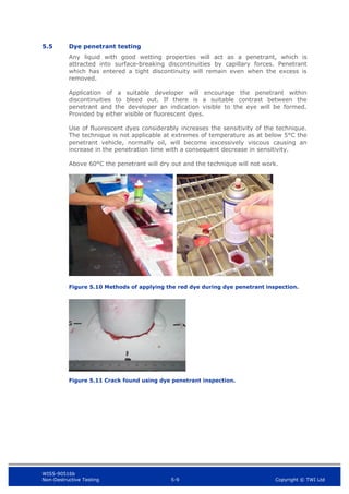
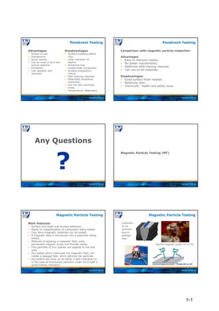
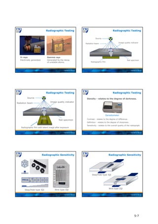
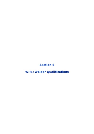
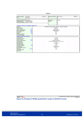
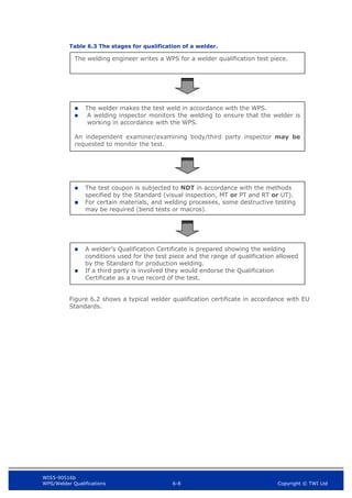
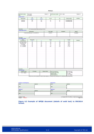
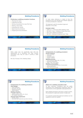
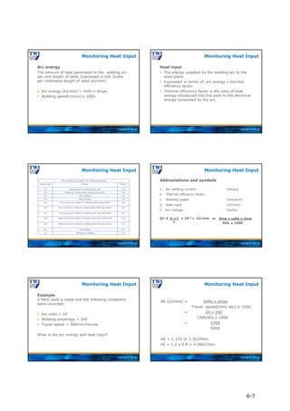
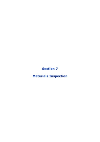
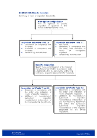
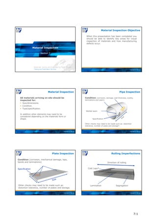
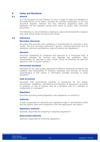
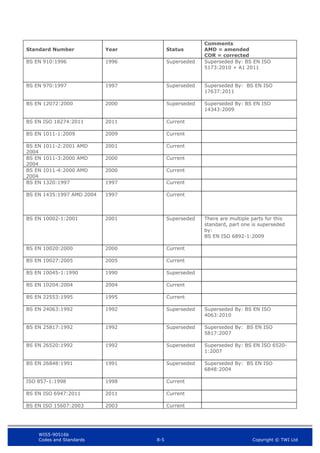
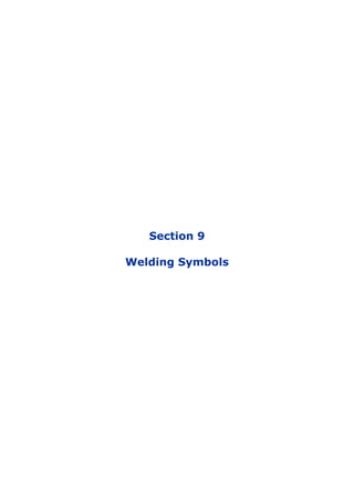
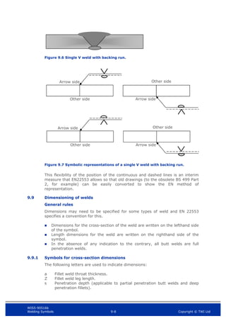
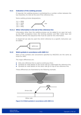
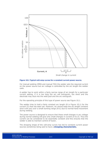
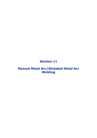
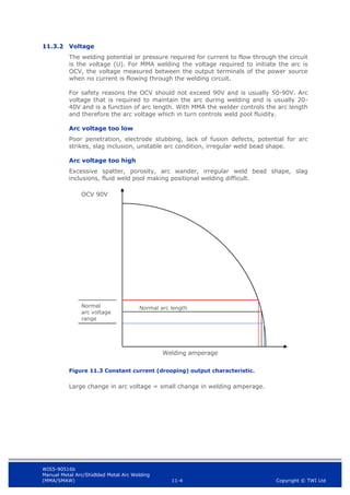
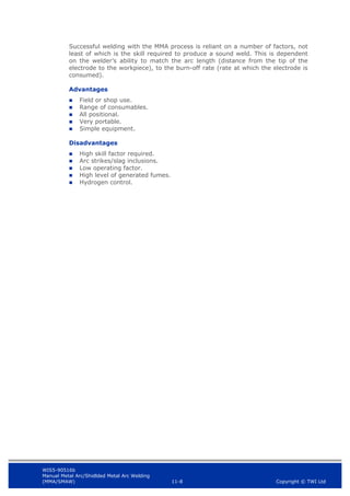
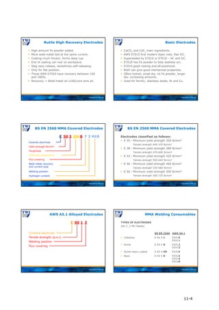
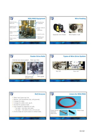
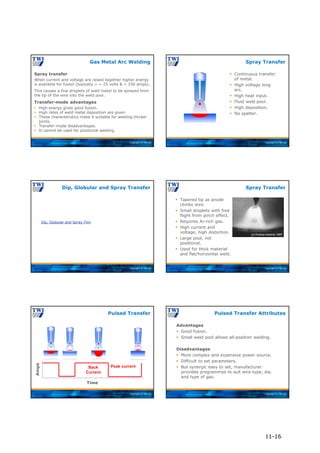
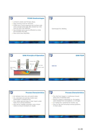
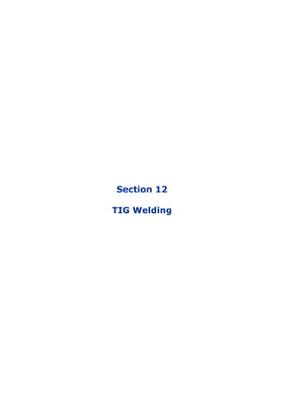
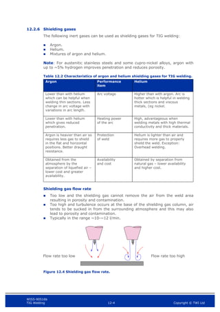
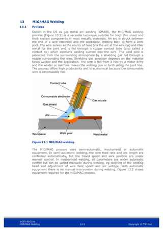
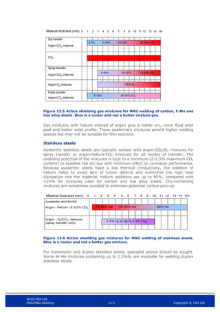
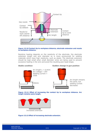
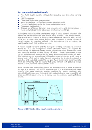
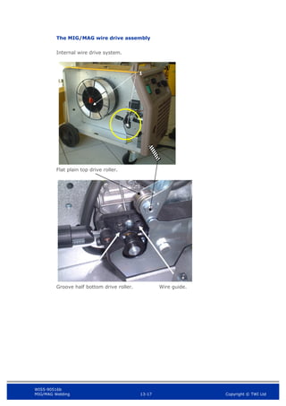
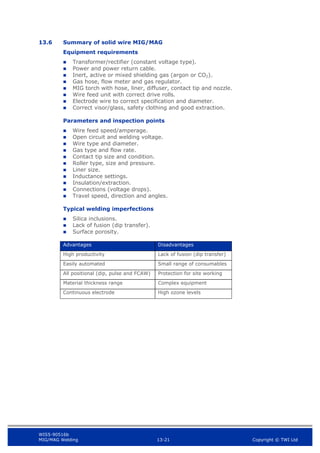
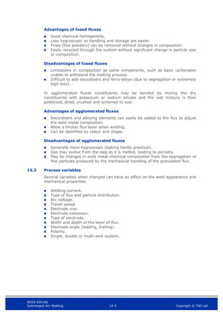
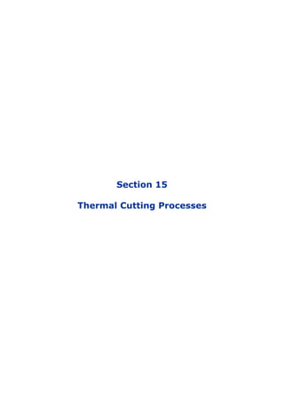
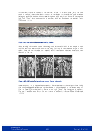
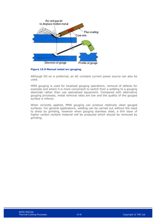
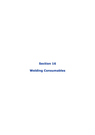
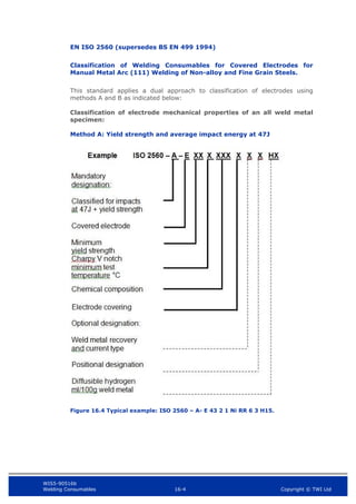
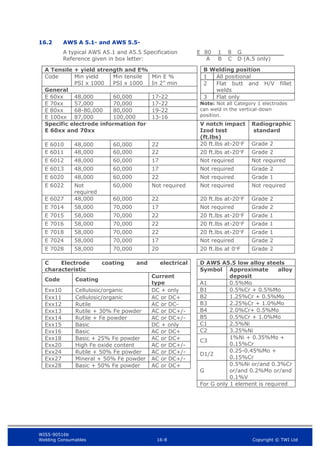
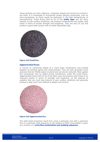
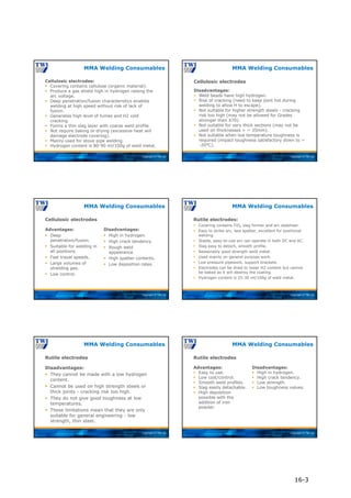
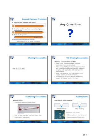
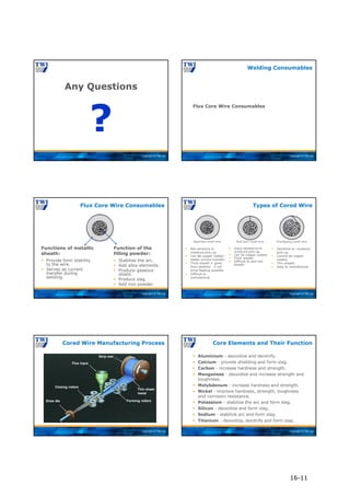
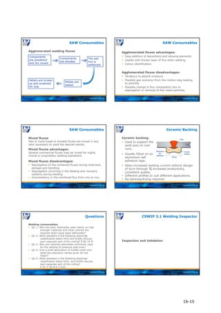
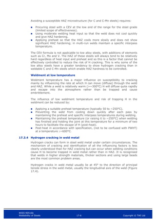
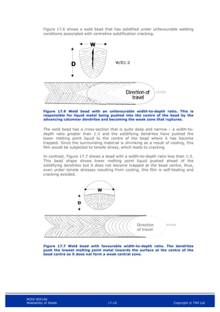
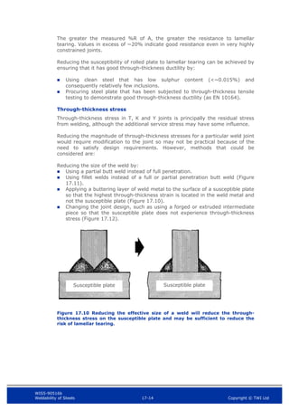
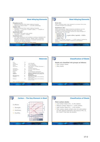
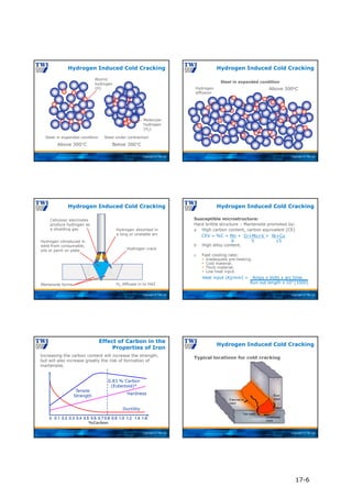
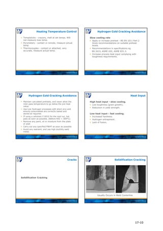
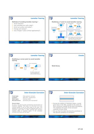
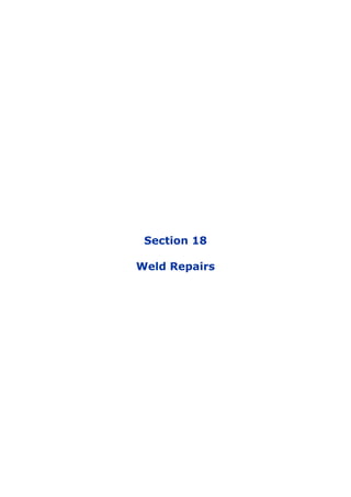
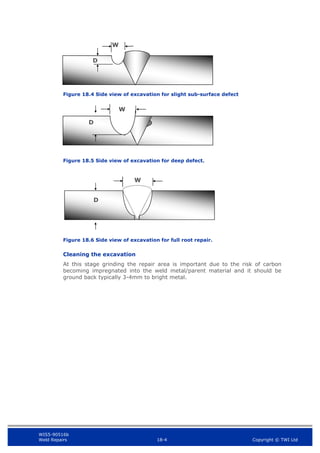
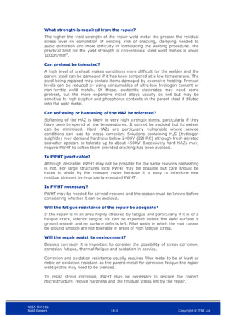
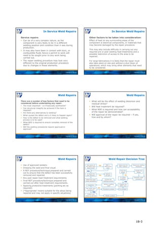
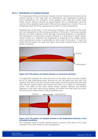
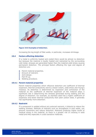
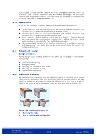
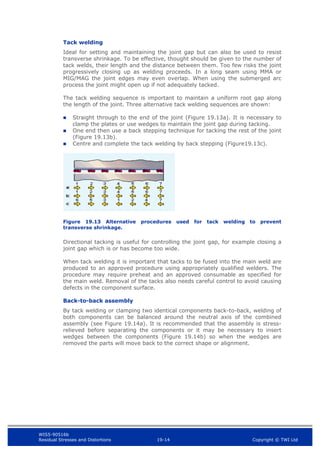
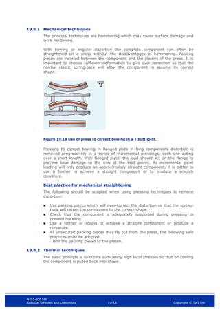
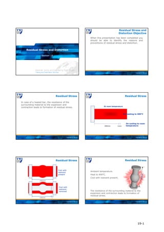
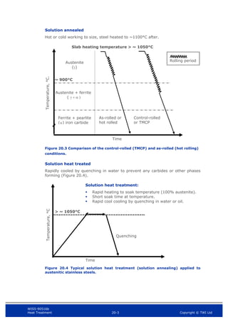
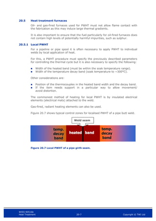
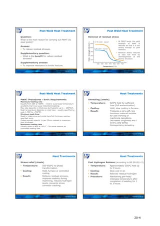
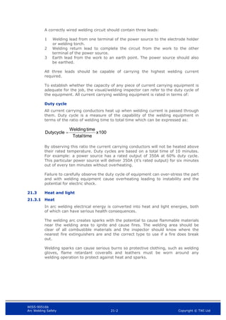
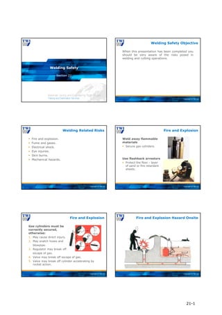
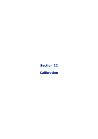
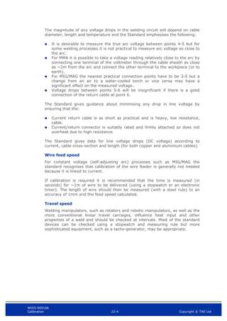
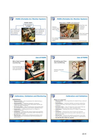
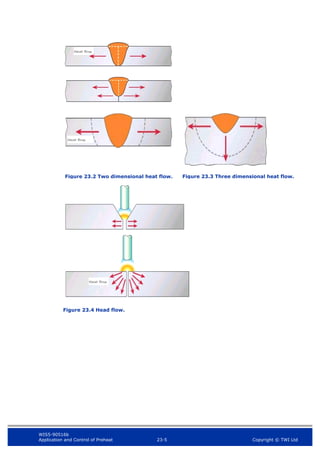
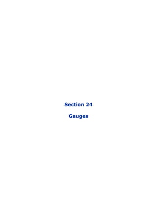
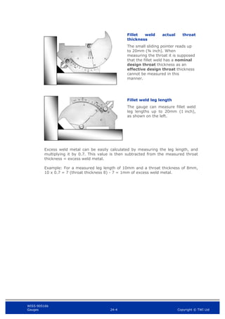
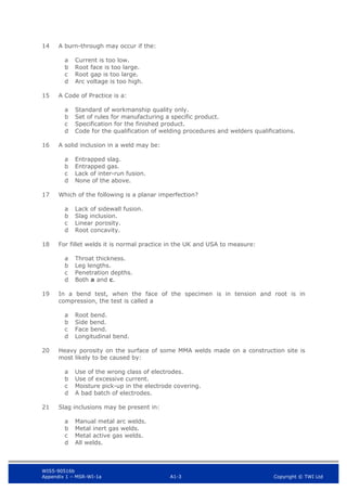
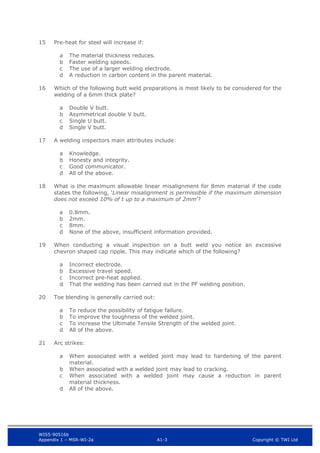
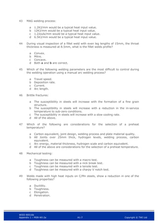
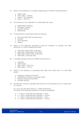
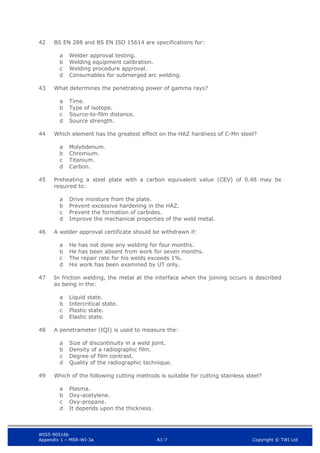
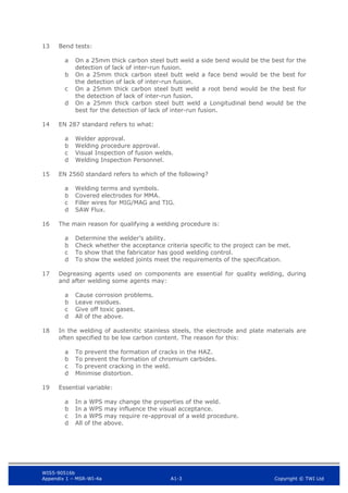
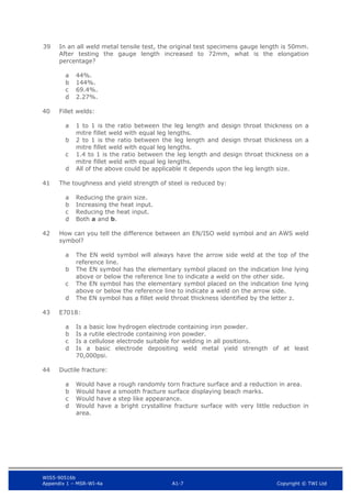
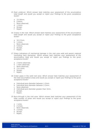
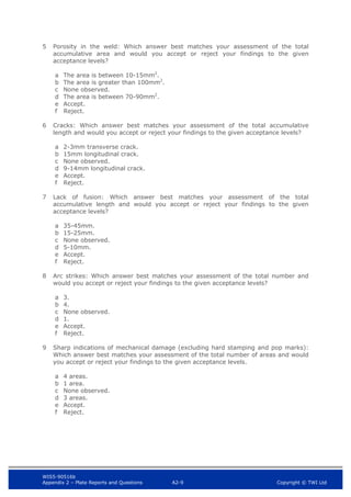
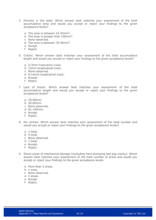
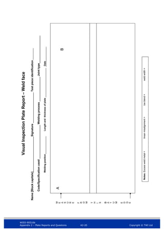
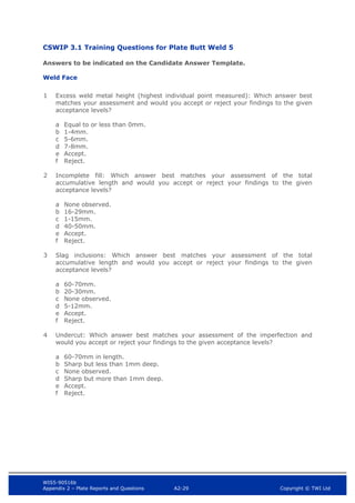
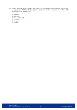
Visual Inspection Pipe Report
Name [Block capitals]
Signature Pipe Ident#
Code/Specification used Welding Process Joint type
Welding position OutsideØ and Thickness Date
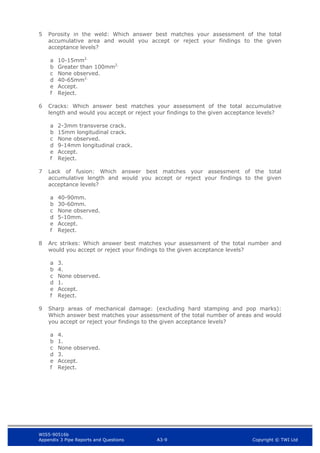
Weld face
A B
C D
Notes:
Excess weld metal height = Misalignment = Weld width = Toe blend =
Notes:
Excess weld metal height = Misalignment = Toe blend = Weld width =
A
C](https://image.slidesharecdn.com/mainbookcswip31weldinginspectorwi-221218121938-b54ec8e9/85/Main_book_CSWIP_3_1_Welding_Inspector_WI-pdf-631-320.jpg)


![WIS5-90516b
Appendix 3 Pipe Reports and Questions A3-27 Copyright © TWI Ltd
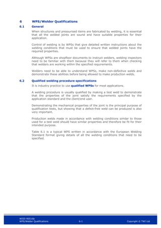
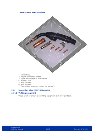
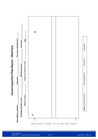
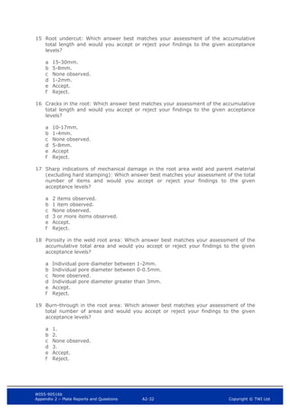
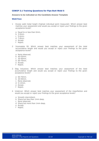
Visual Inspection Pipe Report
Name [Block capitals]
Signature Pipe Ident#
Code/Specification used Welding Process Joint type
Welding position OutsideØ and Thickness Date
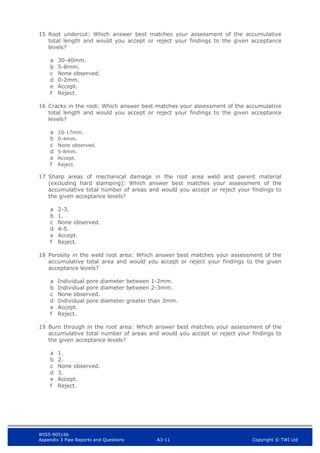
Weld face
A B
C D
Notes:
Excess weld metal height = Misalignment = Weld width = Toe blend =
Notes:
Excess weld metal height = Misalignment = Toe blend = Weld width =
A
C](https://image.slidesharecdn.com/mainbookcswip31weldinginspectorwi-221218121938-b54ec8e9/85/Main_book_CSWIP_3_1_Welding_Inspector_WI-pdf-643-320.jpg)


![WIS5-90516b
Appendix 3 Pipe Reports and Questions A3-34 Copyright © TWI Ltd
Visual Inspection Pipe Report
Name [Block capitals]
Signature Pipe Ident#
Code/Specification used Welding Process Joint type
Welding position OutsideØ and Thickness Date
Weld face
A B
C D
Notes:
Excess weld metal height = Misalignment = Weld width = Toe blend =
Notes:
Excess weld metal height = Misalignment = Toe blend = Weld width =
A
C](https://image.slidesharecdn.com/mainbookcswip31weldinginspectorwi-221218121938-b54ec8e9/85/Main_book_CSWIP_3_1_Welding_Inspector_WI-pdf-655-320.jpg)


![Copyright © TWI Ltd
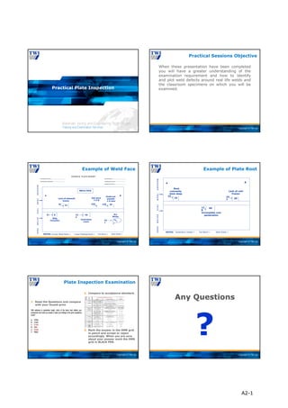
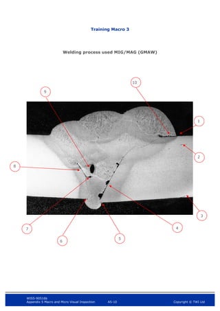
Practical Pipe Inspection
Copyright © TWI Ltd
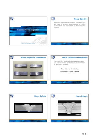
When these presentation have been completed
you will have a greater understanding of the
examination requirement and how to identify
and plot weld defects around real life welds and
the classroom specimens on which you will be
examined.
Practical Sessions Objective
Copyright © TWI Ltd
Pipe Inspection
Copyright © TWI Ltd
HI-LO
Single
Purpose
Welding
Gauge
1
2
3
4
5
6
Root gap
dimension
Internal
alignment
Hi-Low and Root Gap Measurements
Copyright © TWI Ltd
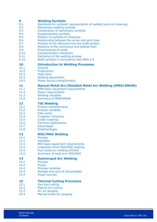
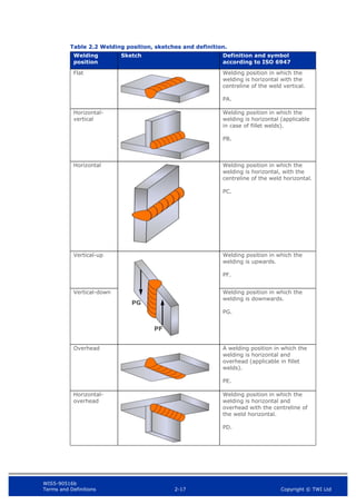
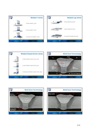
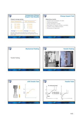
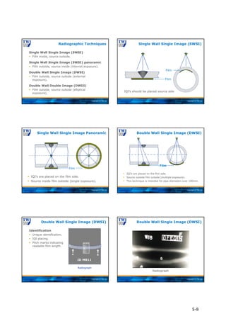
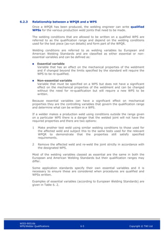
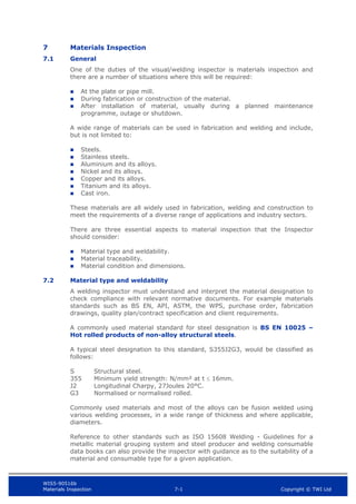
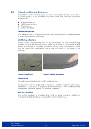
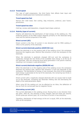
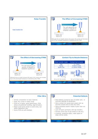
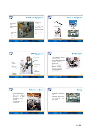
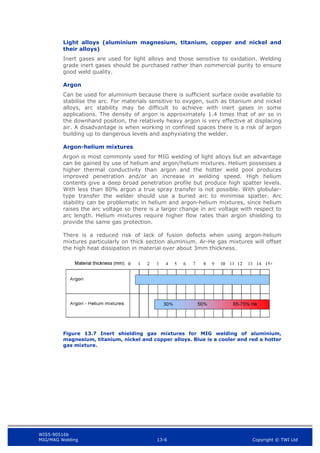
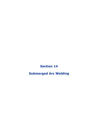
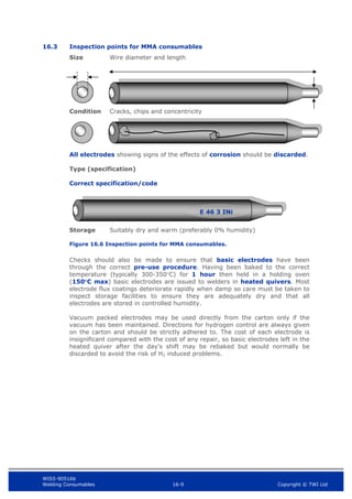
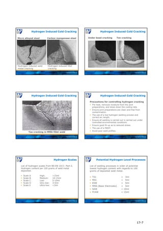
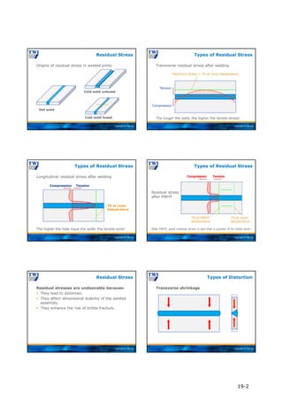
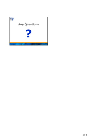
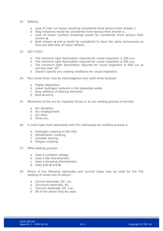
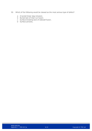
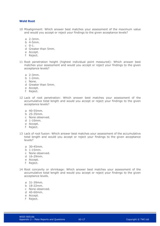
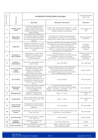
Pipe Inspection Examination
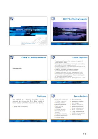
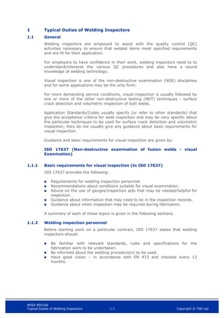
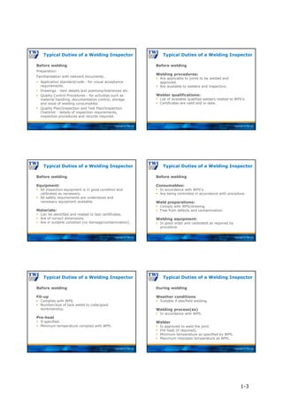
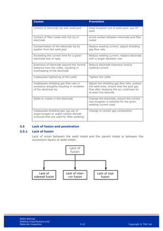
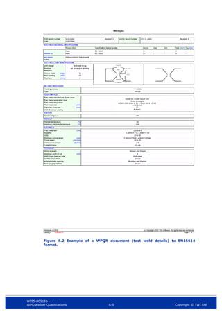
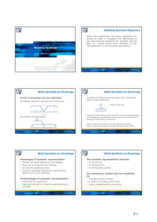
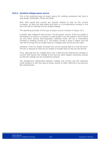
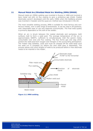
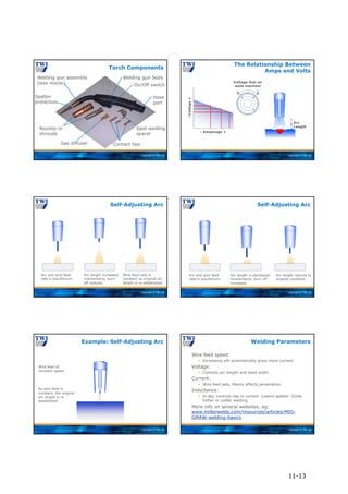
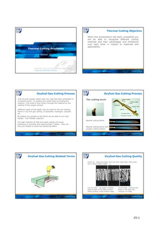
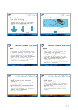
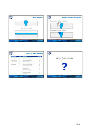
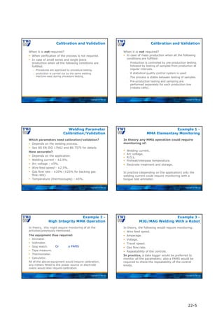
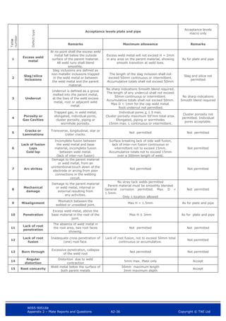
After you have observed an imperfection and
determined its type, you must be able to take
measurements and complete the thumb print
report sketch.
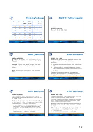
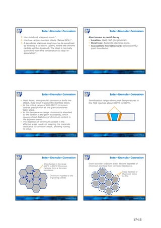
The first thumb print report sketch should be in
the form of a repair map of the weld. (ie all
observations are Identified sized and located).
The thumb print report sketch used in CSWIP
exam will look like the following example.
The thumb print is to used in conjunction with
the multiple choice questions during the
examination .
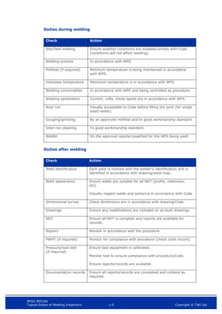
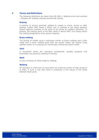
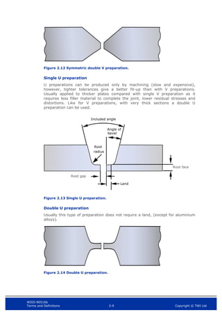
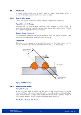
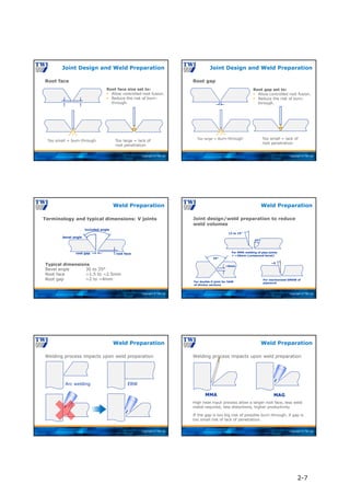
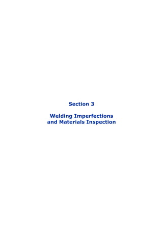
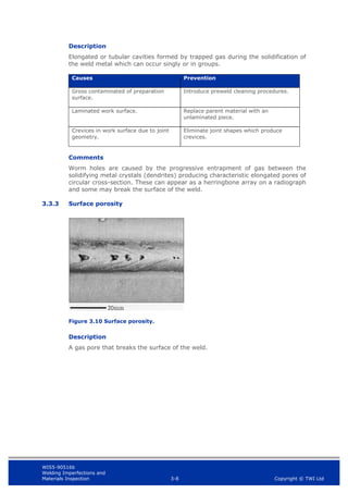
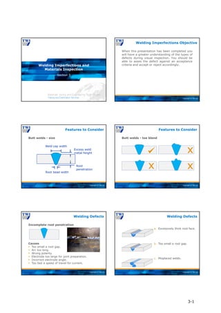
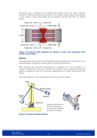
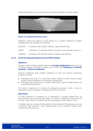
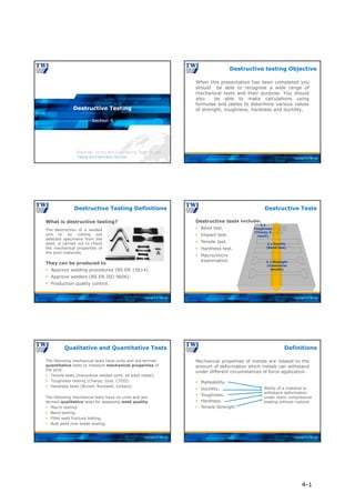
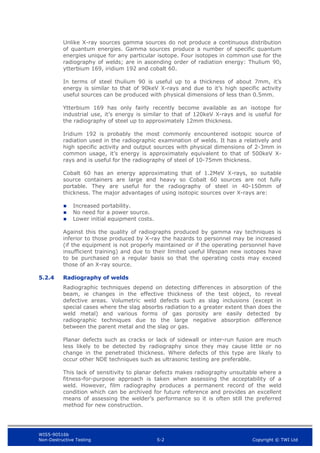
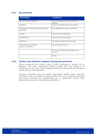
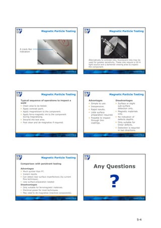
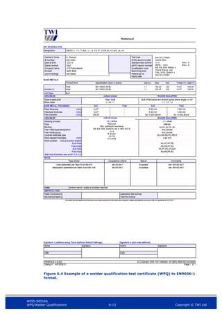
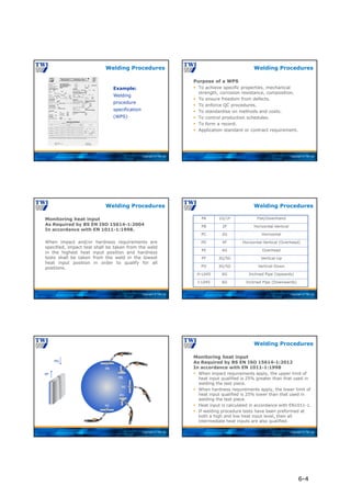
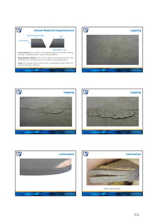
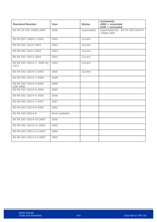
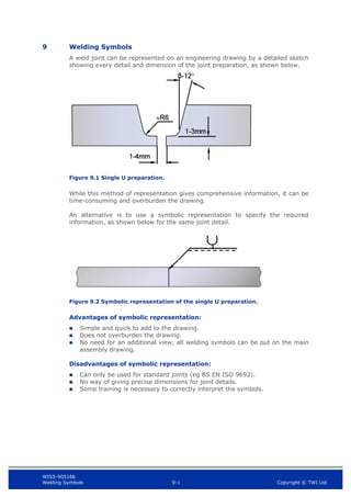
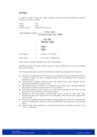
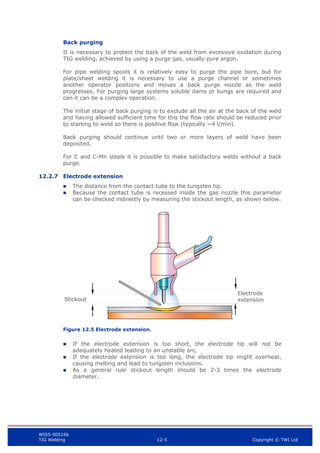
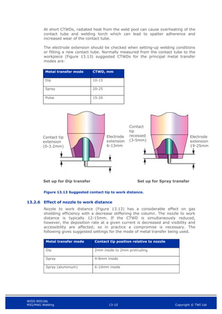
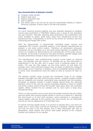
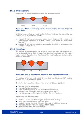
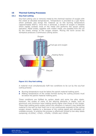
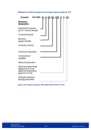
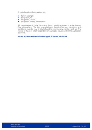
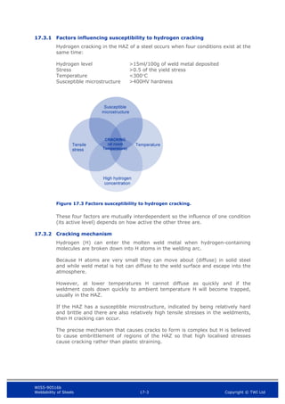
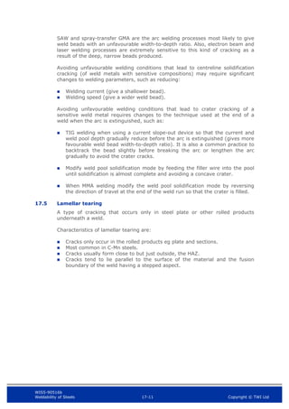
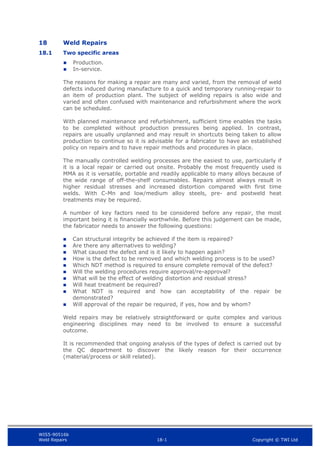
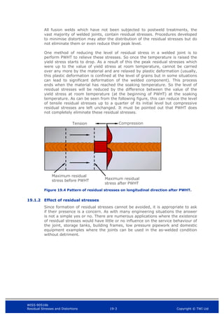
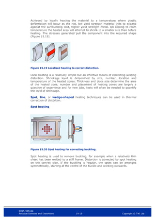
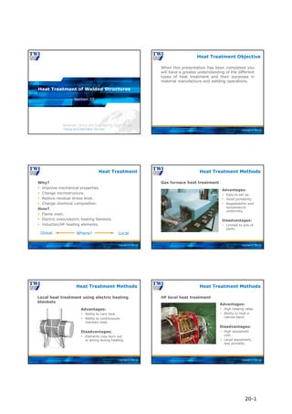
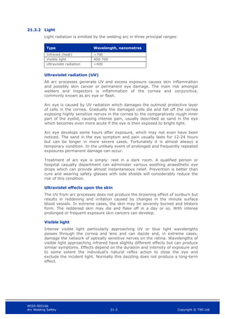
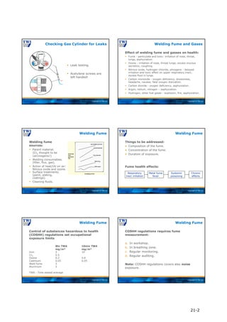
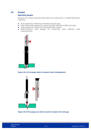
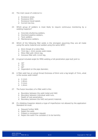
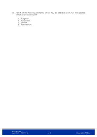
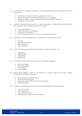
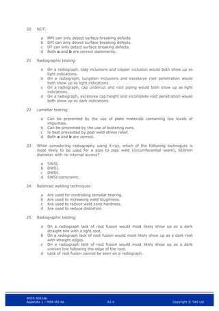
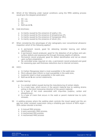
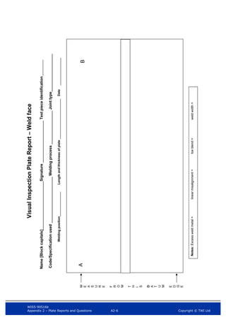
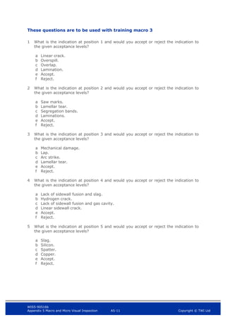
Pipe Inspection Examination
Copyright © TWI Ltd
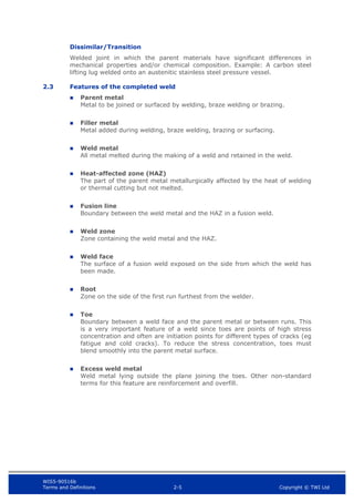
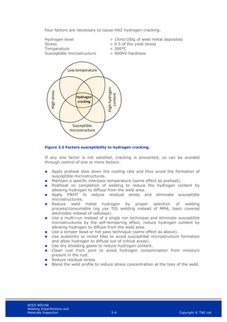
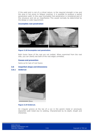
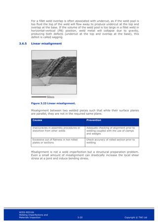
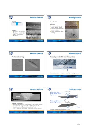
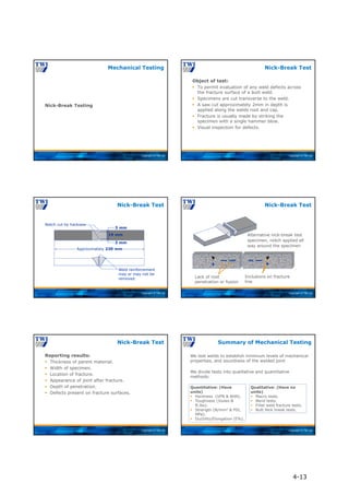
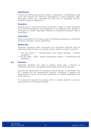
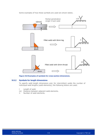
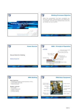
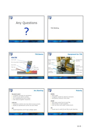
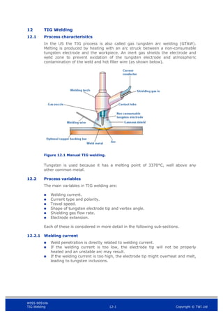
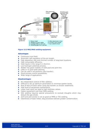
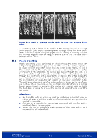
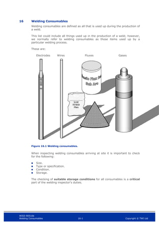
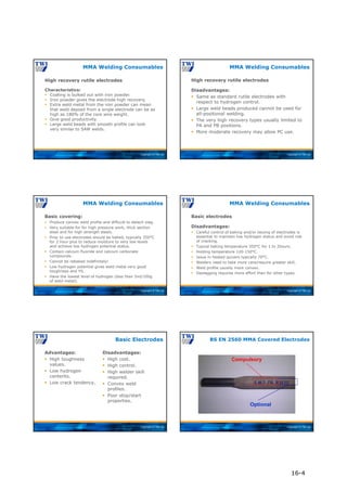
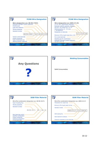
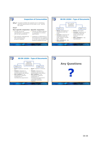
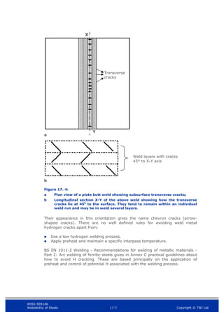
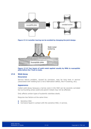
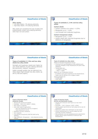
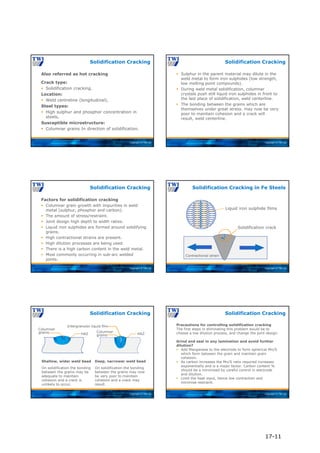
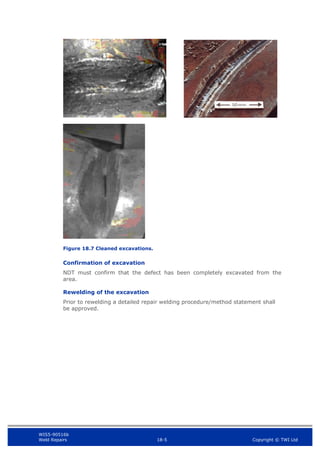
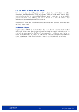
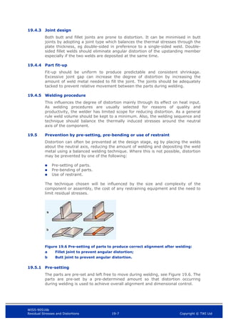
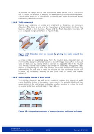
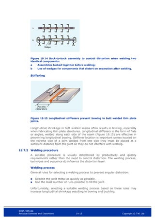
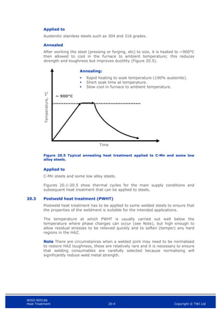
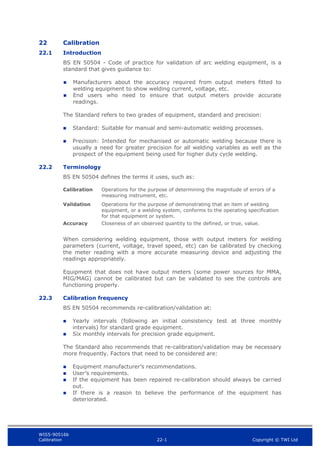
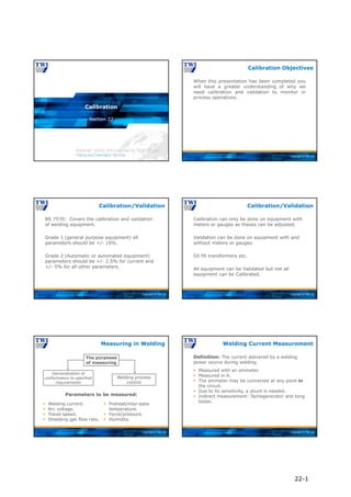
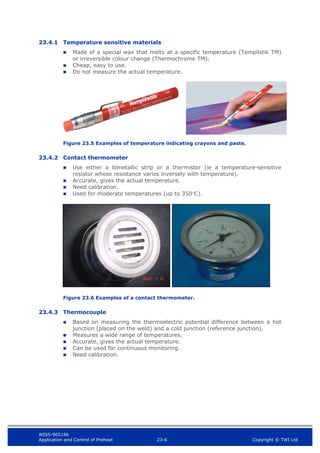
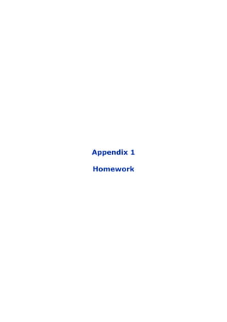
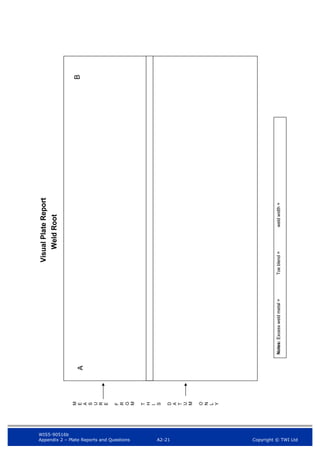
EXAMPLE PIPE REPORT
Name: [Block capitals] ….............................. Signature: ……………….
Date…………………….
Code/Specification used: …………………… Welding process: ……………… Joint type: …………….
Welding position: …………………. Outside Dia & thickness …………… Date ……………………
WELD FACE
C
B
A
98
Arc Strike
20 15
Lack of side
wall fusion
90 10
Undercut
>1.0 mm
140 8
Lack of side
wall fusion
180
46
Under fill
40 12
Under fill
60 5
Slag
inclusion
NOTES:
A
D
C
12
0
15
Slag
2
5
Arc Strike
3
8
8
Lack of side wall fusion
/ incomplete fill
Excess Weld Metal Height = Misalignment = Weld Width = Toe Blend =
NOTES:
Excess Weld Metal Height = Misalignment = Weld Width = Toe Blend =
Pipe Inspection Examination
A3-1](https://image.slidesharecdn.com/mainbookcswip31weldinginspectorwi-221218121938-b54ec8e9/85/Main_book_CSWIP_3_1_Welding_Inspector_WI-pdf-663-320.jpg)


The document provides an overview of the typical duties of welding inspectors, which include assisting with quality control activities to ensure welded items meet specifications. Welding inspectors must understand quality control procedures and have sound welding technology knowledge. Visual inspection is a key non-destructive examination technique used by inspectors, along with other methods like surface crack detection and volumetric inspection of butt welds depending on application. Standards provide acceptance criteria for inspections, and ISO 17637 provides basic requirements for visual inspections.


