Download as PDF, PPTX


![Wrought Carbon Steel Butt Weld Pipe Fittings | TK corporation |
ASME(Inch)
076
077
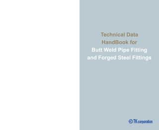
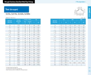
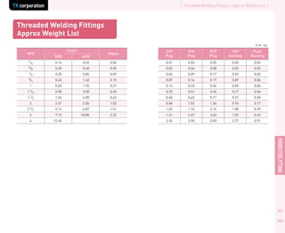
(Unit : inch)
Lap Joint (Stub Ends)
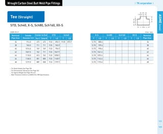
ASME B16.9
Nominal
Pipe Size
(NPS)
Outside Diameter
of Barrel
Long
Pattern
Length, F
[Notes(3),(4)]
Short
Pattern
Length, F
[Notes(3),(4)]
Radius
of
Fillet, R
[Note (5)]
Diameter
of
Lap, G
[Note (6)]Max. Min.
1/2
3/4
1
1 1/4
1 1/2
2
2 1/2
3
3 1/2
4
5
6
8
10
12
14
16
18
20
22
24
0.896
1.106
1.376
1.716
1.965
2.456
2.966
3.596
4.096
4.593
5.683
6.743
8.743
10.913
12.913
14.170
16.180
18.190
20.240
22.240
24.240
0.809
1.019
1.284
1.629
1.869
2.344
2.844
3.469
3.969
4.469
5.532
6.594
8.594
10.719
12.719
13.969
15.969
17.969
19.969
21.969
23.969
3.00
3.00
4.00
4.00
4.00
6.00
6.00
6.00
6.00
6.00
8.00
8.00
8.00
10.00
10.00
12.00
12.00
12.00
12.00
12.00
12.00
2.00
2.00
2.00
2.00
2.00
2.50
2.50
2.50
3.00
3.00
3.00
3.50
4.00
5.00
6.00
6.00
6.00
6.00
6.00
6.00
6.00
0.12
0.12
0.12
0.19
0.25
0.31
0.31
0.38
0.38
0.44
0.44
0.50
0.50
0.50
0.50
0.50
0.50
0.50
0.50
0.50
0.50
1.38
1.69
2.00
2.50
2.88
3.62
4.12
5.00
5.50
6.19
7.31
8.50
10.62
12.75
15.00
16.25
18.50
21.00
23.00
25.25
27.25
GENERAL NOTES:
All dimensions are in millimeters.
See Page 362 for tolerances.
Service conditions and joint construction often dictate stub end length requirements.
Therefore, the purchaser must specify long or short pattern fitting when ordering.
NOTES:
1. Gasket face finish shall be in accordance with ASME B16.5 for raised face flanges.
2. The lap thickness, T, shall not be less than nominal pipe wall thickness. See Page 362 for
maximum tolerance.
3. When short pattern stub ends are used with larger flanges in Classed 300 and 600, with most
sizes in Classes 900 and higher, and when long pattern stub ends are used with larger flanges
in Classes 1500 and 2500, it may be necessary to increase the legnth of the stub ends in order
to avoid covering the weld with the flange. Such increases in length shall be a matter of
agreement between the manufacturer and purchaser.
4. When special facings such as tongue and groove, male and female, etc., are employed,
additional lap thickness must be provided and such additional thickness shall be in addition to
(not included in) the basic length, F.
5. These dimensions conform to the radius estblished for lap joint flanges in ASME B16.5.
6. This dimension conforms to standard machined facings shown in ASME B16.5. The back face
of the lap shall be machined to conform to the surface on shich it sits. Where ring joint facings
are to be appled, use dimension K as given in ASME B16.5.](https://image.slidesharecdn.com/technicaldatahandbookoftkcorporation-190404062406/85/Technical-data-handbook_of_tk_corporation-41-320.jpg)


![| TK corporation |
REFERENCES
394
395
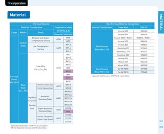
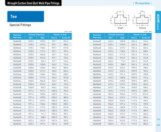
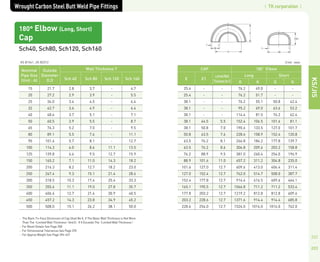
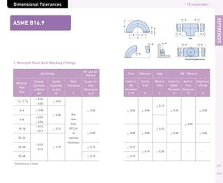
Approx Weight Equation
ELBOW, TEE
1. ELBOW
W = 15.4864 / 360 F T D T 10-5
W = Weight kg
F = Center to End mm
D = Outside Diameter mm
T = Wall Thickness mm
= Angle
2. TEE
W = [0.02466{2Ct1 OD1 OD2 t2 M OD1/2 } 10-3 K]
W = Weight kg C = Center to End mm
OD1 = Outside Diameter mm t1 = Wall Thickness mm
OD2 = Outside Diameter mm t2 = Wall Thickness mm
M = Center to End mm
K = 1 PLATE K = 1.363 PIPE
3. REDUCER
W = 1.3232t1 OD1 OD2 2t1 l 10-5
l = H2 OD1 OD2
2
2
W = Weight kg H = End to End mm
OD1 = Large Size Outside Diameter mm OD2 = Small Size
t1 = Wall Thickness mm
4. CAP
W = 7.85 OD E 2 T 10-6
4
W = Weight kg
OD = Outside Diameter mm
T = Wall Thickness mm
E = End to End mm
REDUCER, CAP](https://image.slidesharecdn.com/technicaldatahandbookoftkcorporation-190404062406/85/Technical-data-handbook_of_tk_corporation-200-320.jpg)


![| TK corporation |
APPENDIX
474
475
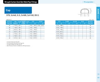
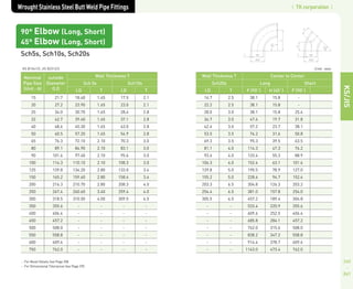
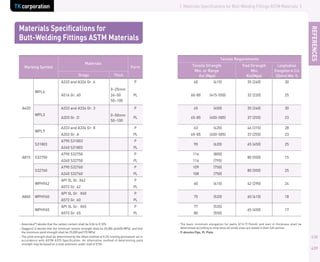
FLOWRESISTANCEEQUIVALENTLENGTHOFWELDBENDELBOWSANDTEES
The infrmation given in the chart above illustrates the resestance of fittings ti
the flow of liquids. This resistance is given in the equivalent of the straight
pipe, and should be assumed as approximate information. Allowances have
been made p for the curvature of elbows, so that the resistance values should
be added to the total center-to end dimensions of the piping configuration.
Example using 6 pipe:
Resistance of Pipe: (6.6+6.4+6.6) = 19.6
+ Resistance of Elbow: = 6.1
Resistance of Tee: = 23.0
= 48.7
Therefore, the total resistance of the entire assembly to the flow of liquid
would be equal to the resistance of 48.7 Linear feet of 6 straight pipe.
Nominal Pipe Size Long Radius Short Radius Welding Tee
1
1-1/4
1-1/2
2
2-1/2
3
4
5
6
8
10
12
14
16
18
20
24
30
36
42
48
1.1
1.4
1.6
2.1
2.6
3.1
4.0
5.1
6.1
8.0
10.0
12.0
13.0
15.0
17.0
19.0
23.0
30.0
38.0
45.0
52.0
1.4
1.8
2.1
2.8
3.3
4.1
5.4
6.7
8.1
11.0
12.0
16.0
18.0
20.0
23.0
25.0
30.0
36.0
42.0
50.0
58.0
3.9
5.2
6.0
7.8
9.3
11.0
15.0
19.0
23.0
30.0
38.0
45.0
49.0
56.0
63.0
71.0
85.0
140.0
170.0
200.0
240.0
Fittings
BEVEL DETAIL - WELDING FITTINGS
Note:
1. See ASME B16.9 for transition contours.
2. x = 0.19 for carbon steel or ferritic alloy steel and 0.12 for austenitic alloy steel.
PLAIN BEVEL
Figure 1
COMPOUND BEVEL
Figure 2
Wall Thickness(T) End Preparation
Less than x [2]
Cut square or slightly chamfer,
at manufacturer s option (not illustrated).
x to 0.88, inclusive Plain bevel as in Figure 1 above.
More than 0.88 Compound bevel as in Figure 2 above.](https://image.slidesharecdn.com/technicaldatahandbookoftkcorporation-190404062406/85/Technical-data-handbook_of_tk_corporation-240-320.jpg)
![| TK corporation |
APPENDIX
476
477
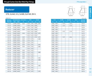
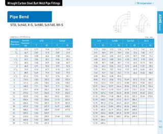
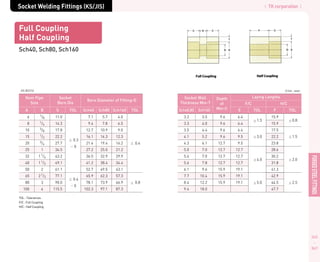
BEVEL FOR WELDNECK FLANGES
NOTES
1. All dimensions are in inches/
2. When the thickness of the hub at the bevel is greater than that of the pipe to which the flange is
joined and the additional thickness is provided on the outside diameter, a taper weld having a
slope not exceeding 1 to 3 may be employed ot, alternatively, the greater outside diameter may be
tapered at the same maximum slope or less, from a point on the welding bevel equal to the
outside diameter of the mating pipe. Similarly, when the greater thickness is provided on the
inside of the flange, it shall be taper-bored from the welding end at the slope not exceeding 1 to 3.
When flanges covered by this Standard are intended for services with light wall, hugher stengh
pipe, the thickness of the hub at the bevel may be greater than that of the pipe to shich the flange
is joined. Under there conditions, a single taper hub may be provided, and the outside diameter of
the hub at the base (dimension X) may also be modified. The additional thickness may be provided
on either inside or outside or partially on each side, but the total additional thickness shall not
exceed one-half times the nominal wall thickness of intended mating pipe. See page 58.
3. The hub transition from the outside diameter to the X diameter shall fall within the
maximum and minimum envelope outlined by the 1:3 max. slope and dashed line.
4. For welding end dimensions, refer to ASME B16.25.
Bevel for
Wall Thickness (T)
from 0.19 in. to
0.88 in. Inclusive
Bevel for
Wall Thickness (T)
Greater Than 0.88 in.
O.D. = Outside Diameter of pipe
I.D. = Inside Diameter of pipe
T = Wall thickness of pipe
Weld Ends
JOINING BUTTWELDING FITTINGS TO PIPE
of equal or less wall thickness
NOTES
1. Buttwelding fittings can be joined to pipe of lesser wall thickness with proper end
preparation and joint design.
2. Above diagrams and recommendations that follow apply to components with ends
originally prepared as standard 37-1/2 or 30 degree bevels and where the wall
thickness of the thicker end to be jined does not exceed 1-1/2times the thinner (pipe) end.
3. The nominal thickness T (pipe) end T (fitting) shall comply with the design requirements
of the applicable section of the ASME B32
1 Code For Pressure Piping.
4. Where the total nominal offser(T2-T1) dose not exceed 3/32” and full penetration and
bonding is obtained during welding, no special treatment is required [see (A)].
5. When the internal offset exceeds 3/32”, taper cut in accordance with (B) ... or tape weld
in accordance with (C)
6. When joining ends with materials of unequal minimum specified yield strenghs (or
unequal allowable stress), the deposited weld metal shall have mechanical properties at
least equal to thoes of the higher strengh (pipe) end.
7. For treatments of ends with inequal external diameters and/or where T2 is thicker than
1-1/2 times T1, refer to the applicable section of the ASME Code, e., B31.4 or B31.8 or B16.9.
(A)
(B)
(C)
PIPE
END
FITTING
END](https://image.slidesharecdn.com/technicaldatahandbookoftkcorporation-190404062406/85/Technical-data-handbook_of_tk_corporation-241-320.jpg)


This document provides technical data and specifications for butt weld pipe fittings manufactured by TK Corporation. It includes dimensions and specifications for carbon steel and stainless steel elbows, tees, reducers, caps, and other fittings in accordance with ASME standards. Dimension tables are provided for nominal pipe sizes from 1/2 inch to 32 inches. The document also references applicable material standards and provides marking and labeling requirements for TK Corporation fittings.


