Hot Tapping Requirement
Prepared by Eng. Wael Elariny
Course contents
Module 1
1. Pipes
2. Flanges
3. Fitting and branch connections
4. Gaskets
Module 2
1. Types of welding processes
2. Welding symbols
3. Welding electrodes identifications
4. Welding procedure specifications
5. Welding Discontinuities
6. Introduction to non destructive test
Module 3
1. Hot tapping Requirements.
Module 4
1. Hot tapping Simulation.
Module 1
1. Pipes
2. Flanges
3. Fitting and branch connections
4. Gaskets
Module 2
1. Types of welding processes
2. Welding symbols
3. Welding electrodes identifications
4. Welding procedure specifications
5. Welding Discontinuities
6. Introduction to non destructive test
Module 3
1. Hot tapping Requirements.
Module 4
1. Hot tapping Simulation.
MODULE 1
PIPING
1- Pipeline specification.
Piping is an assembly of components that include
pipe, valves, fitting ,flanges, bolts, gaskets and
supports used to convey distribute and control flow
of fluid.
Piping must also contain the conveyed fluid and
accommodate internally and externally imposed
loads and thermal movements.
Page  4
Piping is an assembly of components that include
pipe, valves, fitting ,flanges, bolts, gaskets and
supports used to convey distribute and control flow
of fluid.
Piping must also contain the conveyed fluid and
accommodate internally and externally imposed
loads and thermal movements.
Materials .
1. Carbon steels: used for normal corrosion conditions within a
temperature range of -29 °C to 426 °C.
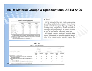
example: ASTM A 106-GR.B
2. Killed carbon steels: used for corrosion conditions within a temperature
range of -29 °C to -46 °C.
example: ASTM A333-GR.6
3. Alloy steels: used for higher temperature and higher corrosion rates.
example: ASTM A335-P9 (9cr – 1 mo)
4. Stainless steels: groups of steels having a minimum of 10.5%chromium
used for excessive corrosion conditions.
example: ASTM A312-TP 316L (18cr-8Ni-2mo)
Page  5
1. Carbon steels: used for normal corrosion conditions within a
temperature range of -29 °C to 426 °C.
example: ASTM A 106-GR.B
2. Killed carbon steels: used for corrosion conditions within a temperature
range of -29 °C to -46 °C.
example: ASTM A333-GR.6
3. Alloy steels: used for higher temperature and higher corrosion rates.
example: ASTM A335-P9 (9cr – 1 mo)
4. Stainless steels: groups of steels having a minimum of 10.5%chromium
used for excessive corrosion conditions.
example: ASTM A312-TP 316L (18cr-8Ni-2mo)
Materials
5. Cast irons: used for underground utilities, sewers and process drainage
systems.
example: grey cast iron, ductile iron.
6. Non metallic: used for better corrosion resistance at low pressure and
normal temperature conditions. Limited to a maximum temperature of
100°C.
example: GRP (glass reinforced plastic) – polyethylene.
7. Plastic lined: Used for chemical resistance, limited to maximum service
temperature of 100°C.
8. Cement lined: used for high corrosion conditions ,low pressure and
normal temperatures, such as seawater.
Page  6
5. Cast irons: used for underground utilities, sewers and process drainage
systems.
example: grey cast iron, ductile iron.
6. Non metallic: used for better corrosion resistance at low pressure and
normal temperature conditions. Limited to a maximum temperature of
100°C.
example: GRP (glass reinforced plastic) – polyethylene.
7. Plastic lined: Used for chemical resistance, limited to maximum service
temperature of 100°C.
8. Cement lined: used for high corrosion conditions ,low pressure and
normal temperatures, such as seawater.
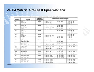
ASTM Material Groups & Specifications
Page  7
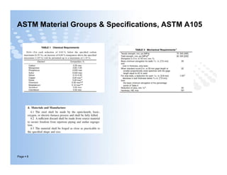
ASTM Material Groups & Specifications, ASTM A105
Page  8
ASTM Material Groups & Specifications, ASTM A106
Page  9
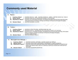
Commonly used Material
Page  10
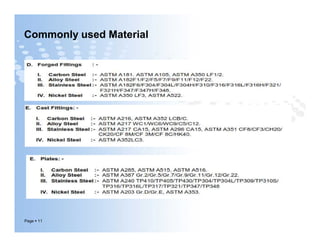
Commonly used Material
Page  11
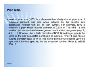
Pipe size.
 Nominal pipe size (NPS) is a dimensionless designator of pipe size. It
indicates standard pipe size when followed by the specific size
designation number with out an inch symbol. For example, NPS 2
indicates a pipe whose outside diameter is 2.375 in. The NPS 12 and
smaller pipe has outside diameter greater than the size designator (say, 2,
4, 6, . . .). However, the outside diameter of NPS 14 and larger pipe is the
same as the size designator in inches. For example, NPS 14 pipe has an
outside diameter equal to 14 in. The inside diameter will depend upon the
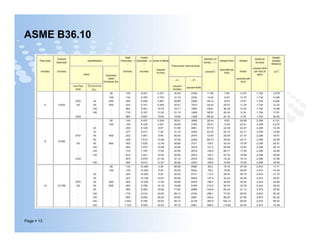
pipe wall thickness specified by the schedule number. Refer to ASME
B36.10 .
Page  12
 Nominal pipe size (NPS) is a dimensionless designator of pipe size. It
indicates standard pipe size when followed by the specific size
designation number with out an inch symbol. For example, NPS 2
indicates a pipe whose outside diameter is 2.375 in. The NPS 12 and
smaller pipe has outside diameter greater than the size designator (say, 2,
4, 6, . . .). However, the outside diameter of NPS 14 and larger pipe is the
same as the size designator in inches. For example, NPS 14 pipe has an
outside diameter equal to 14 in. The inside diameter will depend upon the
pipe wall thickness specified by the schedule number. Refer to ASME
B36.10 .
ASME B36.10
Page  13
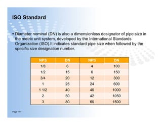
ISO Standard
 Diameter nominal (DN) is also a dimensionless designator of pipe size in
the metric unit system, developed by the International Standards
Organization (ISO).It indicates standard pipe size when followed by the
specific size designation number.
NPS DN NPS DN
Page  14
1/8 6 4 100
1/2 15 6 150
3/4 20 12 300
1 25 24 600
1 1/2 40 40 1000
2 50 42 1050
3 80 60 1500
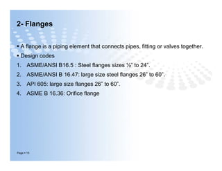
2- Flanges
 A flange is a piping element that connects pipes, fitting or valves together.
 Design codes
1. ASME/ANSI B16.5 : Steel flanges sizes ½” to 24”.
2. ASME/ANSI B 16.47: large size steel flanges 26” to 60”.
3. API 605: large size flanges 26” to 60”.
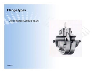
4. ASME B 16.36: Orifice flange
Page  15
 A flange is a piping element that connects pipes, fitting or valves together.
 Design codes
1. ASME/ANSI B16.5 : Steel flanges sizes ½” to 24”.
2. ASME/ANSI B 16.47: large size steel flanges 26” to 60”.
3. API 605: large size flanges 26” to 60”.
4. ASME B 16.36: Orifice flange
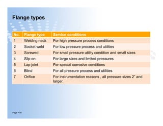
Flange types
No. Flange type Service conditions
1 Welding neck For high pressure process conditions
2 Socket weld For low pressure process and utilities
3 Screwed For small pressure utility condition and small sizes
4 Slip on For large sizes and limited pressures
5 Lap joint For special corrosive conditions
Page  16
5 Lap joint For special corrosive conditions
6 Blind For all pressure process and utilities
7 Orifice For instrumentation reasons , all pressure sizes 2” and
larger.
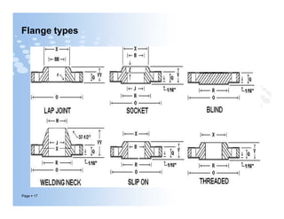
Flange types
Page  17
Flange types
Orifice flange ASME B 16.36
Page  18
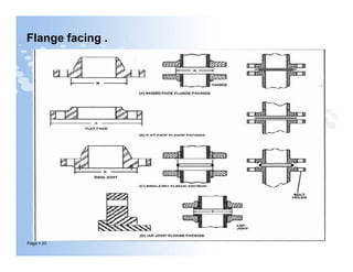
Flange facing
 Flat face (FF)
 Raised face (RF)
 Ring joint (RJ)
 Lap joint (LJ)
 Tongue and groove (T&G)
 Male and female (M&F)
Page  19
 Flat face (FF)
 Raised face (RF)
 Ring joint (RJ)
 Lap joint (LJ)
 Tongue and groove (T&G)
 Male and female (M&F)
Flange facing .
Page  20
Flange pressure / temperature ratings
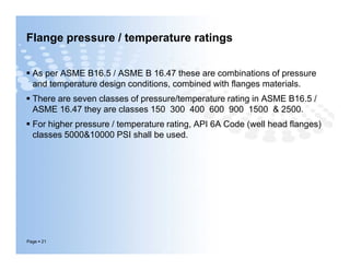
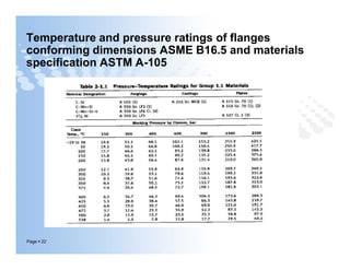
 As per ASME B16.5 / ASME B 16.47 these are combinations of pressure
and temperature design conditions, combined with flanges materials.
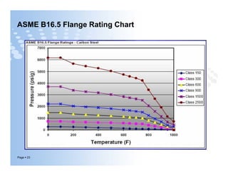
 There are seven classes of pressure/temperature rating in ASME B16.5 /
ASME 16.47 they are classes 150 300 400 600 900 1500 & 2500.
 For higher pressure / temperature rating, API 6A Code (well head flanges)
classes 5000&10000 PSI shall be used.
Page  21
 As per ASME B16.5 / ASME B 16.47 these are combinations of pressure
and temperature design conditions, combined with flanges materials.
 There are seven classes of pressure/temperature rating in ASME B16.5 /
ASME 16.47 they are classes 150 300 400 600 900 1500 & 2500.
 For higher pressure / temperature rating, API 6A Code (well head flanges)
classes 5000&10000 PSI shall be used.
Temperature and pressure ratings of flanges
conforming dimensions ASME B16.5 and materials
specification ASTM A-105
Page  22
ASME B16.5 Flange Rating Chart
Page  23
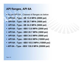
API flanges, API 6A
 As per API 6A , Classes of flanges as below
 API 6A - Type - 6B 13.8 MPA (2000 psi)
 API 6A - Type - 6B 20.7 MPA (3000 psi)
 API 6A - Type - 6B 34.5 MPA (5000 psi)
 API 6A - Type - 6BX 13.8 MPA (2000 psi)
 API 6A - Type - 6BX 20.7 MPA (3000 psi)
 API 6A - Type - 6BX 34.5 MPA (5000 psi)
 API 6A - Type - 6BX 69.0 MPA (10000 psi)
 API 6A - Type - 6BX 103.5 MPA (15000 psi)
 API 6A - Type - 6BX 138.0 MPA (20000 psi)
Page  24
 As per API 6A , Classes of flanges as below
 API 6A - Type - 6B 13.8 MPA (2000 psi)
 API 6A - Type - 6B 20.7 MPA (3000 psi)
 API 6A - Type - 6B 34.5 MPA (5000 psi)
 API 6A - Type - 6BX 13.8 MPA (2000 psi)
 API 6A - Type - 6BX 20.7 MPA (3000 psi)
 API 6A - Type - 6BX 34.5 MPA (5000 psi)
 API 6A - Type - 6BX 69.0 MPA (10000 psi)
 API 6A - Type - 6BX 103.5 MPA (15000 psi)
 API 6A - Type - 6BX 138.0 MPA (20000 psi)
API Flanges
Page  25
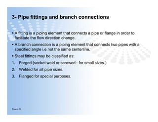
3- Pipe fittings and branch connections
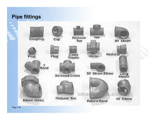
 A fitting is a piping element that connects a pipe or flange in order to
facilitate the flow direction change.
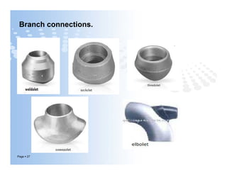
 A branch connection is a piping element that connects two pipes with a
specified angle i.e not the same centerline.
 Steel fittings may be classified as:
1. Forged (socket weld or screwed : for small sizes.)
2. Welded for all pipe sizes.
3. Flanged for special purposes.
Page  26
 A fitting is a piping element that connects a pipe or flange in order to
facilitate the flow direction change.
 A branch connection is a piping element that connects two pipes with a
specified angle i.e not the same centerline.
 Steel fittings may be classified as:
1. Forged (socket weld or screwed : for small sizes.)
2. Welded for all pipe sizes.
3. Flanged for special purposes.
Branch connections.
Page  27
Pipe fittings
Page  28
Pipe fittings and branch connections
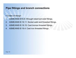
 Codes of design:
1. ASME/ANSI B16.9: Wrought steel butt weld fittings.
2. ASME/ANSI B 16.11: Socket weld and threaded fittings.
3. ASME/ANSI B 16.15: Cast bronze threaded fittings .
4. ASME/ANSI B 16.4: Cast iron threaded fittings .
Page  29
 Codes of design:
1. ASME/ANSI B16.9: Wrought steel butt weld fittings.
2. ASME/ANSI B 16.11: Socket weld and threaded fittings.
3. ASME/ANSI B 16.15: Cast bronze threaded fittings .
4. ASME/ANSI B 16.4: Cast iron threaded fittings .
Pipe fittings and branch connections
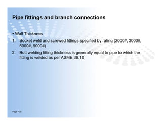
 Wall Thickness
1. Socket weld and screwed fittings specified by rating (2000#, 3000#,
6000#, 9000#)
2. Butt welding fitting thickness is generally equal to pipe to which the
fitting is welded as per ASME 36.10
Page  30
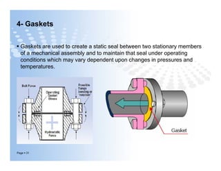
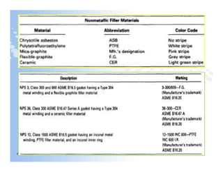
4- Gaskets
 Gaskets are used to create a static seal between two stationary members
of a mechanical assembly and to maintain that seal under operating
conditions which may vary dependent upon changes in pressures and
temperatures.
Page  31
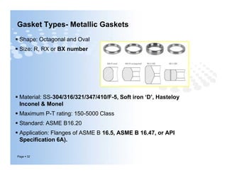
Gasket Types- Metallic Gaskets
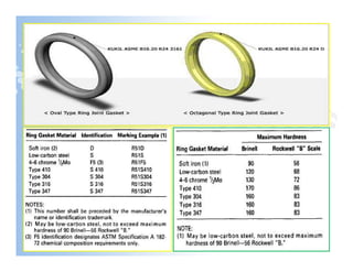
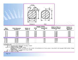
 Shape: Octagonal and Oval
 Size: R, RX or BX number
 Material: SS-304/316/321/347/410/F-5, Soft iron ‘D’, Hasteloy
Inconel & Monel
 Maximum P-T rating: 150-5000 Class
 Standard: ASME B16.20
 Application: Flanges of ASME B 16.5, ASME B 16.47, or API
Specification 6A).
Page  32
 Shape: Octagonal and Oval
 Size: R, RX or BX number
 Material: SS-304/316/321/347/410/F-5, Soft iron ‘D’, Hasteloy
Inconel & Monel
 Maximum P-T rating: 150-5000 Class
 Standard: ASME B16.20
 Application: Flanges of ASME B 16.5, ASME B 16.47, or API
Specification 6A).
Page  33
Page  34
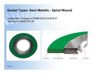
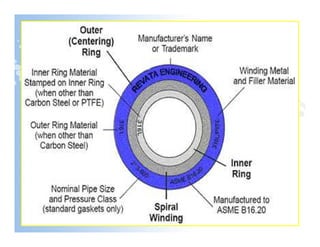
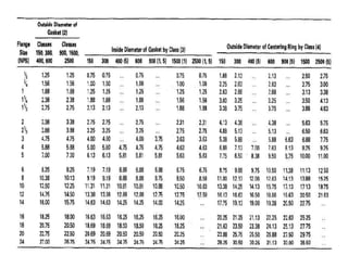
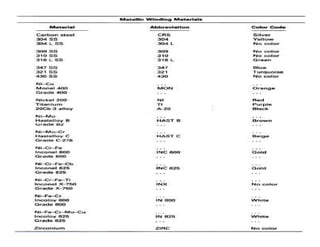
Gasket Types- Semi Metallic - Spiral Wound
Application: Flanges of ASME B16.5 & B16.47
Standard: ASME B16.20
Page  35
Page  36
Page  37
Page  38
Page  39
MODULE 2
WELDING
1-Welding Processes
41
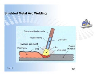
Shielded Metal Arc Welding
Page  42
42
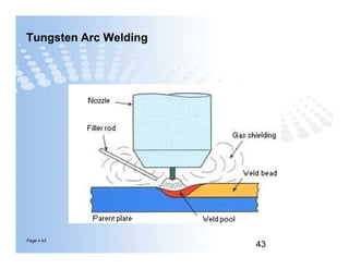
Tungsten Arc Welding
Page  43
43
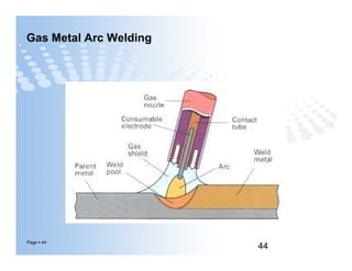
Gas Metal Arc Welding
Page  44
44
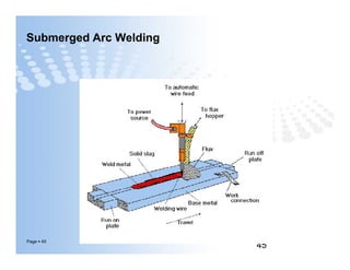
Submerged Arc Welding
Page  45
45
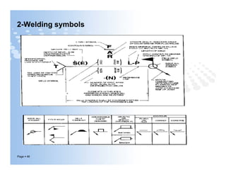
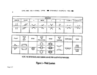
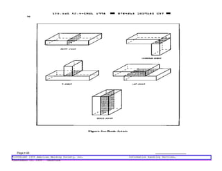
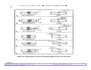
2-Welding symbols
Page  46
Page  47
Page  48
COPYRIGHT 1999 American Welding Society, Inc. Information Handling Services,
September 10, 1999 06:07:26
COPYRIGHT 1999 American Welding Society, Inc. Information Handling Services,
September 10, 1999 06:07:26
Page  49
COPYRIGHT 1999 American Welding Society, Inc. Information Handling Services,
September 10, 1999 06:07:26
COPYRIGHT 1999 American Welding Society, Inc. Information Handling Services,
September 10, 1999 06:07:26
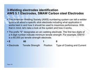
3-Welding electrodes identification
AWS 5.1 Electrodes, SMAW Carbon steel Electrodes
 The American Welding Society (AWS) numbering system can tell a welder
quite a bit about a specific stick electrode including what application it
works best in and how it should be used to maximize performance. With
that in mind, let's take a look at the system and how it works.
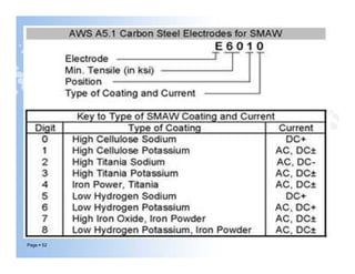
 The prefix "E" designates an arc welding electrode. The first two digits of
a 4-digit number indicate minimum tensile strength. For example, E6010
is a 60,000 psi tensile strength electrode.
 E 60 1 0
 Electrode Tensile Strength Position Type of Coating and Current
Page  50
 The American Welding Society (AWS) numbering system can tell a welder
quite a bit about a specific stick electrode including what application it
works best in and how it should be used to maximize performance. With
that in mind, let's take a look at the system and how it works.
 The prefix "E" designates an arc welding electrode. The first two digits of
a 4-digit number indicate minimum tensile strength. For example, E6010
is a 60,000 psi tensile strength electrode.
 E 60 1 0
 Electrode Tensile Strength Position Type of Coating and Current
Welding electrodes identification
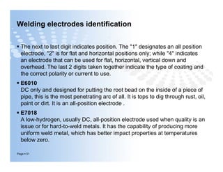
 The next to last digit indicates position. The "1" designates an all position
electrode, "2" is for flat and horizontal positions only; while "4" indicates
an electrode that can be used for flat, horizontal, vertical down and
overhead. The last 2 digits taken together indicate the type of coating and
the correct polarity or current to use.
 E6010
DC only and designed for putting the root bead on the inside of a piece of
pipe, this is the most penetrating arc of all. It is tops to dig through rust, oil,
paint or dirt. It is an all-position electrode .
 E7018
A low-hydrogen, usually DC, all-position electrode used when quality is an
issue or for hard-to-weld metals. It has the capability of producing more
uniform weld metal, which has better impact properties at temperatures
below zero.
Page  51
 The next to last digit indicates position. The "1" designates an all position
electrode, "2" is for flat and horizontal positions only; while "4" indicates
an electrode that can be used for flat, horizontal, vertical down and
overhead. The last 2 digits taken together indicate the type of coating and
the correct polarity or current to use.
 E6010
DC only and designed for putting the root bead on the inside of a piece of
pipe, this is the most penetrating arc of all. It is tops to dig through rust, oil,
paint or dirt. It is an all-position electrode .
 E7018
A low-hydrogen, usually DC, all-position electrode used when quality is an
issue or for hard-to-weld metals. It has the capability of producing more
uniform weld metal, which has better impact properties at temperatures
below zero.
Page  52
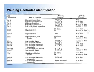
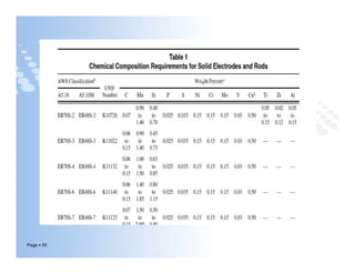
Welding electrodes identification
Page  53
Welding electrodes identification
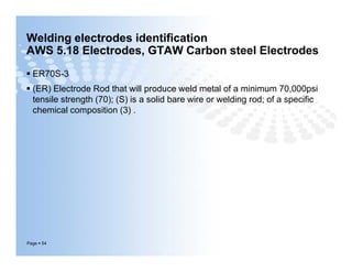
AWS 5.18 Electrodes, GTAW Carbon steel Electrodes
 ER70S-3
 (ER) Electrode Rod that will produce weld metal of a minimum 70,000psi
tensile strength (70); (S) is a solid bare wire or welding rod; of a specific
chemical composition (3) .
Page  54
Page  55
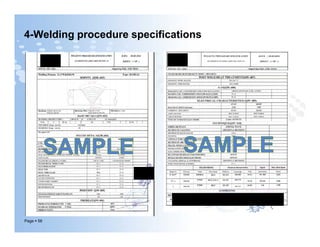
4-Welding procedure specifications
Page  56
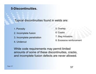
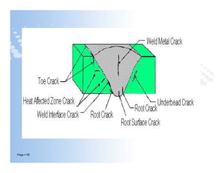
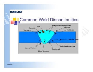
5-Discontinuities.
Typical discontinuities found in welds are:
1. Porosity
2. Incomplete fusion
3. Incomplete penetration
4. Undercut
5. Overlap
6. Cracks
7. Slag inclusions
8. Excessive reinforcement
Page  57
57
While code requirements may permit limited
amounts of some of these discontinuities, cracks,
and incomplete fusion defects are never allowed.
1. Porosity
2. Incomplete fusion
3. Incomplete penetration
4. Undercut
5. Overlap
6. Cracks
7. Slag inclusions
8. Excessive reinforcement
Page  58
Page  59
6-Introduction to NDT.
Overview of Six Most Common NDT Methods
Page  60
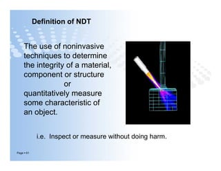
The use of noninvasive
techniques to determine
the integrity of a material,
component or structure
or
quantitatively measure
some characteristic of
an object.
Definition of NDT
Page  61
The use of noninvasive
techniques to determine
the integrity of a material,
component or structure
or
quantitatively measure
some characteristic of
an object.
i.e. Inspect or measure without doing harm.
What are Some Uses
of NDE Methods?
 Flaw Detection and Evaluation
 Leak Detection
 Location Determination
 Dimensional Measurements
 Structure and Microstructure Characterization
 Estimation of Mechanical and Physical Properties
 Stress (Strain) and Dynamic Response Measurements
 Material Sorting and Chemical Composition Determination
Page  62
 Flaw Detection and Evaluation
 Leak Detection
 Location Determination
 Dimensional Measurements
 Structure and Microstructure Characterization
 Estimation of Mechanical and Physical Properties
 Stress (Strain) and Dynamic Response Measurements
 Material Sorting and Chemical Composition Determination
When are NDE Methods Used?
– To assist in product development
– To screen or sort incoming materials
– To monitor, improve or control manufacturing
processes
– To verify proper processing such as heat treating
– To verify proper assembly
– To inspect for in-service damage
There are NDE application at almost any stage
in the production or life cycle of a component.
There are NDE application at almost any stage
in the production or life cycle of a component.
Page  63
– To assist in product development
– To screen or sort incoming materials
– To monitor, improve or control manufacturing
processes
– To verify proper processing such as heat treating
– To verify proper assembly
– To inspect for in-service damage
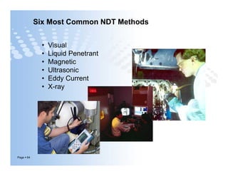
Six Most Common NDT Methods
• Visual
• Liquid Penetrant
• Magnetic
• Ultrasonic
• Eddy Current
• X-ray
Page  64
• Visual
• Liquid Penetrant
• Magnetic
• Ultrasonic
• Eddy Current
• X-ray
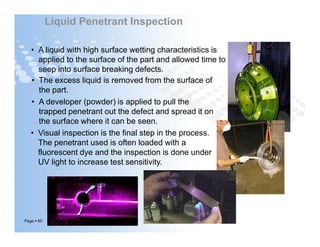
• A liquid with high surface wetting characteristics is
applied to the surface of the part and allowed time to
seep into surface breaking defects.
• The excess liquid is removed from the surface of
the part.
• A developer (powder) is applied to pull the
trapped penetrant out the defect and spread it on
the surface where it can be seen.
Liquid Penetrant Inspection
Page  65
• A developer (powder) is applied to pull the
trapped penetrant out the defect and spread it on
the surface where it can be seen.
• Visual inspection is the final step in the process.
The penetrant used is often loaded with a
fluorescent dye and the inspection is done under
UV light to increase test sensitivity.
Magnetic Particle Inspection
The part is magnetized. Finely milled iron particles coated with a dye
pigment are then applied to the specimen. These particles are attracted
to magnetic flux leakage fields and will cluster to form an indication
directly over the discontinuity. This indication can be visually detected
under proper lighting conditions.
Page  66
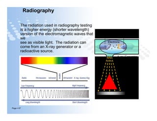
Radiography
The radiation used in radiography testing
is a higher energy (shorter wavelength)
version of the electromagnetic waves that
we
see as visible light. The radiation can
come from an X-ray generator or a
radioactive source.
High Electrical Potential
Electrons
-+
X-ray Generator
or Radioactive
Source Creates
Radiation
Page  67
X-ray Generator
or Radioactive
Source Creates
Radiation
Exposure Recording Device
Radiation
Penetrate
the Sample
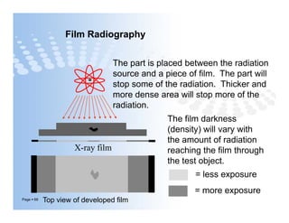
Film Radiography
The part is placed between the radiation
source and a piece of film. The part will
stop some of the radiation. Thicker and
more dense area will stop more of the
radiation.
The film darkness
(density) will vary with
the amount of radiation
reaching the film through
the test object.
Page  68 Top view of developed film
X-ray film
= more exposure
= less exposure
The film darkness
(density) will vary with
the amount of radiation
reaching the film through
the test object.
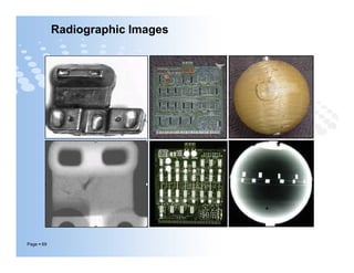
Radiographic Images
Page  69
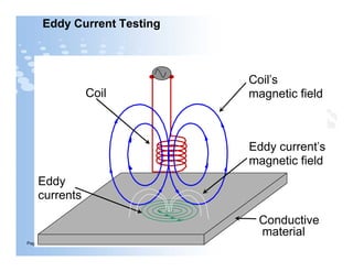
Coil
Coil's
magnetic field
Eddy current's
Eddy Current Testing
Page  70
Conductive
material
Eddy
currents
Eddy current's
magnetic field
Eddy Current Testing
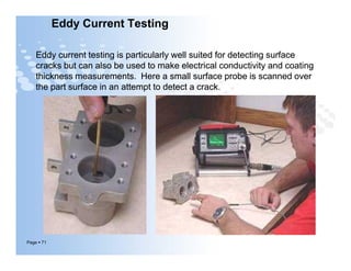
Eddy current testing is particularly well suited for detecting surface
cracks but can also be used to make electrical conductivity and coating
thickness measurements. Here a small surface probe is scanned over
the part surface in an attempt to detect a crack.
Eddy current testing is particularly well suited for detecting surface
cracks but can also be used to make electrical conductivity and coating
thickness measurements. Here a small surface probe is scanned over
the part surface in an attempt to detect a crack.
Page  71
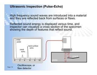
High frequency sound waves are introduced into a material
and they are reflected back from surfaces or flaws.
Reflected sound energy is displayed versus time, and
inspector can visualize a cross section of the specimen
showing the depth of features that reflect sound. f
Ultrasonic Inspection (Pulse-Echo)
Page  72
plate
crack
0 2 4 6 8 10
initial
pulse
crack
echo
back surface
echo
Oscilloscope, or
flaw detector
screen
Module 3
Hot Tapping Requirements
1- Definition
 Hot Tapping is the precise process of drilling a hole in an on- stream piping
system without spilling its contents or interrupting its flow.
or in a practical sense
 Hot Tapping is a means by which access is made to the inside of an
operational pipeline, using either a drill or a circular cutter. Applications
include attachment of a branch connection to the line, installation of an
internal probe or monitor, and to stop or redirect flow in a line for
maintenance or repair purposes.
 Implies positioning a branch fitting on an operating pressurized line,
flowing or stagnant. Then cutting a hole in the run through the branch to
allow connection to the flowing media. Normally implies using a welded
fitting.
Page  74
 Hot Tapping is the precise process of drilling a hole in an on- stream piping
system without spilling its contents or interrupting its flow.
or in a practical sense
 Hot Tapping is a means by which access is made to the inside of an
operational pipeline, using either a drill or a circular cutter. Applications
include attachment of a branch connection to the line, installation of an
internal probe or monitor, and to stop or redirect flow in a line for
maintenance or repair purposes.
 Implies positioning a branch fitting on an operating pressurized line,
flowing or stagnant. Then cutting a hole in the run through the branch to
allow connection to the flowing media. Normally implies using a welded
fitting.

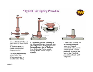
Typical Hot Tapping Procedure
Page  75
(Shown: Standard Valve used
when tapping to install lateral
lines.
SANDWICH® Valve
Option allows temporary
plugging operation.)
1.A fitting is permanently
secured to the line.
2.A permanent valve is
installed on the fitting.
 3.A Tapping Machine is installed on
the fitting, and the valve is opened. After
pilot drill penetrates, the tapping machine
fills with product, and air is purged
from the housing. The tap is make
through the line and the coupon is
retained.
 4.The valve is closed, and
the tapping machine is
removed. A branch
connection is added, and the
valve is opened. The new
connection is ready to put
into service. This field-
proven Procedure is quick
and precise.

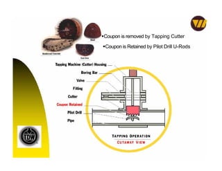
Coupon is removed by Tapping Cutter
Coupon is Retained by Pilot Drill U-Rods
Page  76
2- Purpose of Hot Tapping.
 Hot tapping is usually performed when it is not feasible, or is impractical,
to take the equipment or piping out of service, or to purge or clean it by
conventional methods. With proper review to determine that a hot tap is
appropriate, and development and conformance to job specific
procedures, many hot tap connections have been safely made without
interfering with the process operation.
Page  77
3-Parameters that affect Hot Tapping.
3.1Internal pipeline condition
3.1.1Content :
 Welding and hot tapping should not be performed on piping or equipment
containing the following materials:
a. Vapor/air or vapor/oxygen mixtures near or within their flammable
explosive range.
b. Oxygen or oxygen enriched atmosphere.
c. Compressed air systems, unless known to be free of flammables and
combustibles
d. Hydrogen
e. Temperature-sensitive, chemically reactive materials
f. Caustics, amines, and acids (such as HF acid)
g. Certain unsaturated hydrocarbons (such as ethylene)
Page  78
3.1Internal pipeline condition
3.1.1Content :
 Welding and hot tapping should not be performed on piping or equipment
containing the following materials:
a. Vapor/air or vapor/oxygen mixtures near or within their flammable
explosive range.
b. Oxygen or oxygen enriched atmosphere.
c. Compressed air systems, unless known to be free of flammables and
combustibles
d. Hydrogen
e. Temperature-sensitive, chemically reactive materials
f. Caustics, amines, and acids (such as HF acid)
g. Certain unsaturated hydrocarbons (such as ethylene)
3-Parameters that affect Hot Tapping.
3.1.2 Flow in lines
Higher flow increases the weld cooling rate and the risk of cracking.
Therefore, when welding, it is desirable to provide some minimum level of
flow while avoiding high flow rates. The need for a minimum level of flow
is a trade-off between the need to minimize the risks of burn-through and
cracking.
 For metal thickness between 1/4 in. (6.4 mm) and 1/2 in.(12.7 mm), flow
also increases the weld cooling rate and risk of cracking. Minimizing the
flow rate reduces the risk of cracking and keeps the risk of burn through
low. For metal thickness greater than 1/2 in. (12.7 mm), the effect of flow
on both weld cooling rates and the risk of burn-through may be negligible.
 Recommended flow rate during welding
 0.4<X<1.2 m/s in case of liquid.
 0.4< X< NOLIMIT in case of Gas.
Page  79
3.1.2 Flow in lines
Higher flow increases the weld cooling rate and the risk of cracking.
Therefore, when welding, it is desirable to provide some minimum level of
flow while avoiding high flow rates. The need for a minimum level of flow
is a trade-off between the need to minimize the risks of burn-through and
cracking.
 For metal thickness between 1/4 in. (6.4 mm) and 1/2 in.(12.7 mm), flow
also increases the weld cooling rate and risk of cracking. Minimizing the
flow rate reduces the risk of cracking and keeps the risk of burn through
low. For metal thickness greater than 1/2 in. (12.7 mm), the effect of flow
on both weld cooling rates and the risk of burn-through may be negligible.
 Recommended flow rate during welding
 0.4<X<1.2 m/s in case of liquid.
 0.4< X< NOLIMIT in case of Gas.
3-Parameters that affect Hot Tapping.
3.1.3 Pipe Line content pressure & Temperature
The pipeline content pressure and temperature should not exceed the
allowable pressure / temperature rating of the used hot tapping machine.
the leak test pressure for tapping machine and fitting should not exceed 1.1
of the pipeline operating pressure during tapping operation.
3.2 Pipeline Specification
3.2.1 pipeline material and grade.
Pipeline material and grade should be identified in order to select :
1. Suitable pilot drill and cutter material.
2. Suitable welding procedure specification.
Page  80
3.1.3 Pipe Line content pressure & Temperature
The pipeline content pressure and temperature should not exceed the
allowable pressure / temperature rating of the used hot tapping machine.
the leak test pressure for tapping machine and fitting should not exceed 1.1
of the pipeline operating pressure during tapping operation.
3.2 Pipeline Specification
3.2.1 pipeline material and grade.
Pipeline material and grade should be identified in order to select :
1. Suitable pilot drill and cutter material.
2. Suitable welding procedure specification.
3-Parameters that affect Hot Tapping.
3.2.2 pipeline metal thickness and outer diameter
 The piping or equipment base metal thickness must provide support for
the new connection and the hot tapping machine. Alternately, reinforcing
pads or auxiliary support of the hot tapping machine may be provided.
 A minimum base metal thickness of 3/16 in. (4.8 mm) is recommended for
most applications of welding and hot tapping. The actual minimum
thickness is a function of the thickness required for strength, plus a safety
factor, usually 3/32 in. (2.4 mm), to prevent burn through.
 Pipeline outer diameter , wall thickness and the required branch
connection diameter are determined the selection of branch connection
type (weldolet , split tee , --), and also determined the type of cutter to be
used in case of flat plate condition.
Page  81
3.2.2 pipeline metal thickness and outer diameter
 The piping or equipment base metal thickness must provide support for
the new connection and the hot tapping machine. Alternately, reinforcing
pads or auxiliary support of the hot tapping machine may be provided.
 A minimum base metal thickness of 3/16 in. (4.8 mm) is recommended for
most applications of welding and hot tapping. The actual minimum
thickness is a function of the thickness required for strength, plus a safety
factor, usually 3/32 in. (2.4 mm), to prevent burn through.
 Pipeline outer diameter , wall thickness and the required branch
connection diameter are determined the selection of branch connection
type (weldolet , split tee , --), and also determined the type of cutter to be
used in case of flat plate condition.
3-Parameters that affect Hot Tapping.
3.3 branch connection
3.3.1 branch connection size & internal diameter
It Should be specified as it affect cutter size and tapping machine
selection.
3.3.2 branch connection length
Branch connection length (top of flange – top of pipe) should be
measured .
Page  82
3.3 branch connection
3.3.1 branch connection size & internal diameter
It Should be specified as it affect cutter size and tapping machine
selection.
3.3.2 branch connection length
Branch connection length (top of flange – top of pipe) should be
measured .
3-Parameters that affect Hot Tapping
 3.4 valves
 The hot tap valve to be used must be of adequate size and rating, be of
proper metallurgy, and be a full opening valve.
 The hot tap valve should be tested for seat leakage prior to installation
(see API Std 598).
 During installation the valve should be centered on the nozzle flange or
fixture.
 Run the boring bar through the valve opening to be sure the cutter does
not jam or drag.
 Valve face to face dimensions must be determined.
Page  83
 3.4 valves
 The hot tap valve to be used must be of adequate size and rating, be of
proper metallurgy, and be a full opening valve.
 The hot tap valve should be tested for seat leakage prior to installation
(see API Std 598).
 During installation the valve should be centered on the nozzle flange or
fixture.
 Run the boring bar through the valve opening to be sure the cutter does
not jam or drag.
 Valve face to face dimensions must be determined.
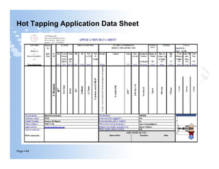
Hot Tapping Application Data Sheet
Page  84
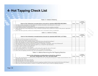
4- Hot Tapping Check List
Page  85
4- Hot Tapping Check List
Page  86
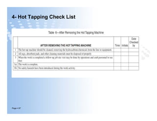
4- Hot Tapping Check List
Page  87
Hot Tapping Simulation
Simulate tapping machine in workshop
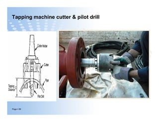
Tapping machine cutter & pilot drill
Page  89
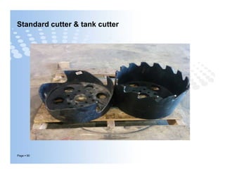
Standard cutter & tank cutter
Page  90
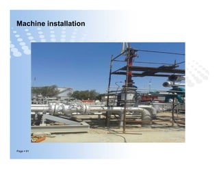
Machine installation
Page  91
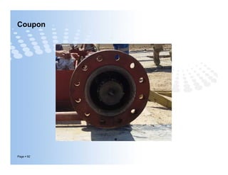
Coupon
Page  92
References
 ASME B 16.5
 ASME B 16.47
 ASME B 36.10
 AWS A 5.1
 AWS A 2.4
 AWS A 5.18
 API 6A
 API RP 2201
 TDW hot tapping procedure and application by William Jarvis
 Piping fundamentals by Mohinder L Nayyar, Bechtel Power Corporation
Page  93
 ASME B 16.5
 ASME B 16.47
 ASME B 36.10
 AWS A 5.1
 AWS A 2.4
 AWS A 5.18
 API 6A
 API RP 2201
 TDW hot tapping procedure and application by William Jarvis
 Piping fundamentals by Mohinder L Nayyar, Bechtel Power Corporation
Prepared by Eng.Wael Elariny
THANK YOU