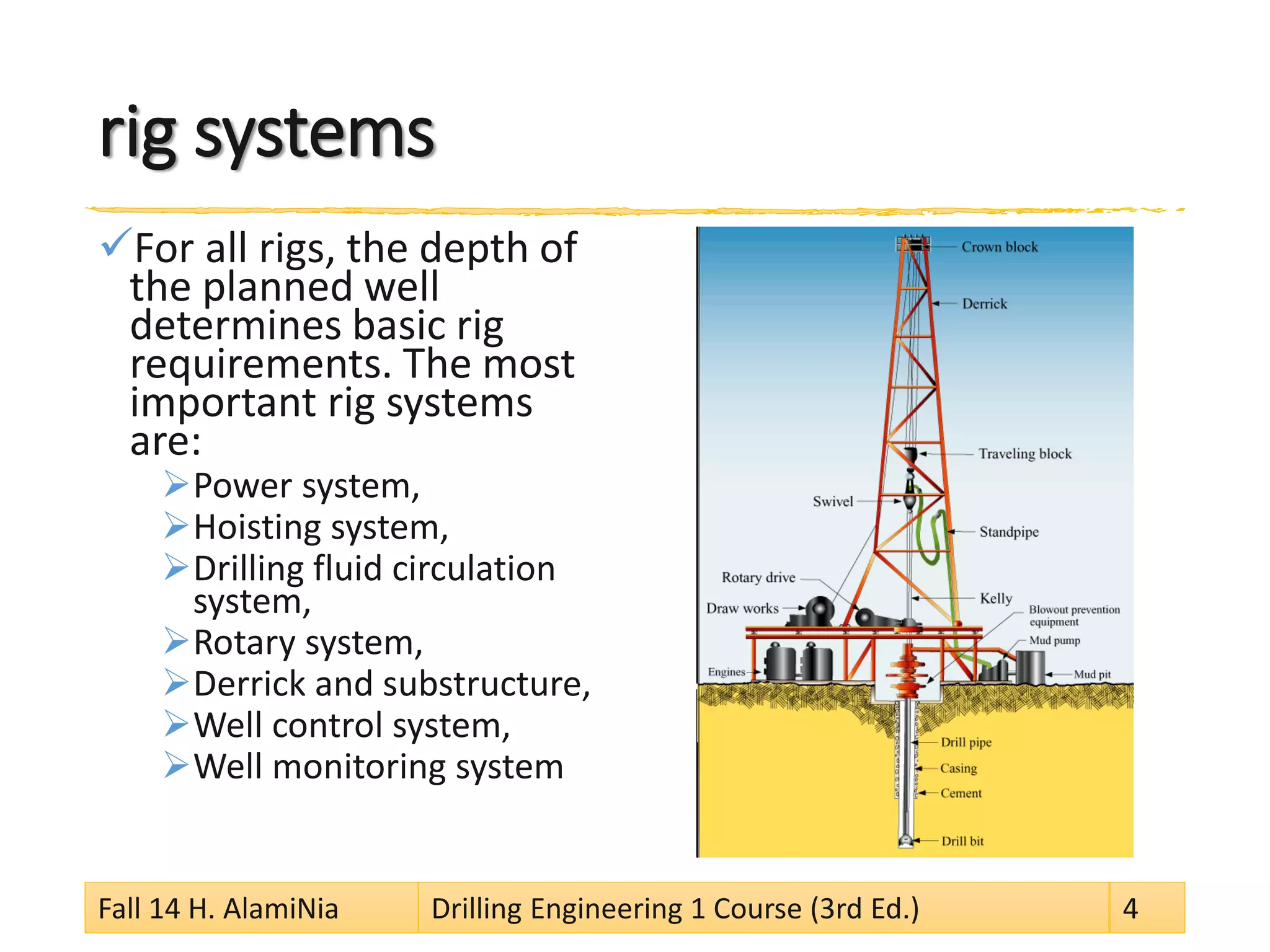
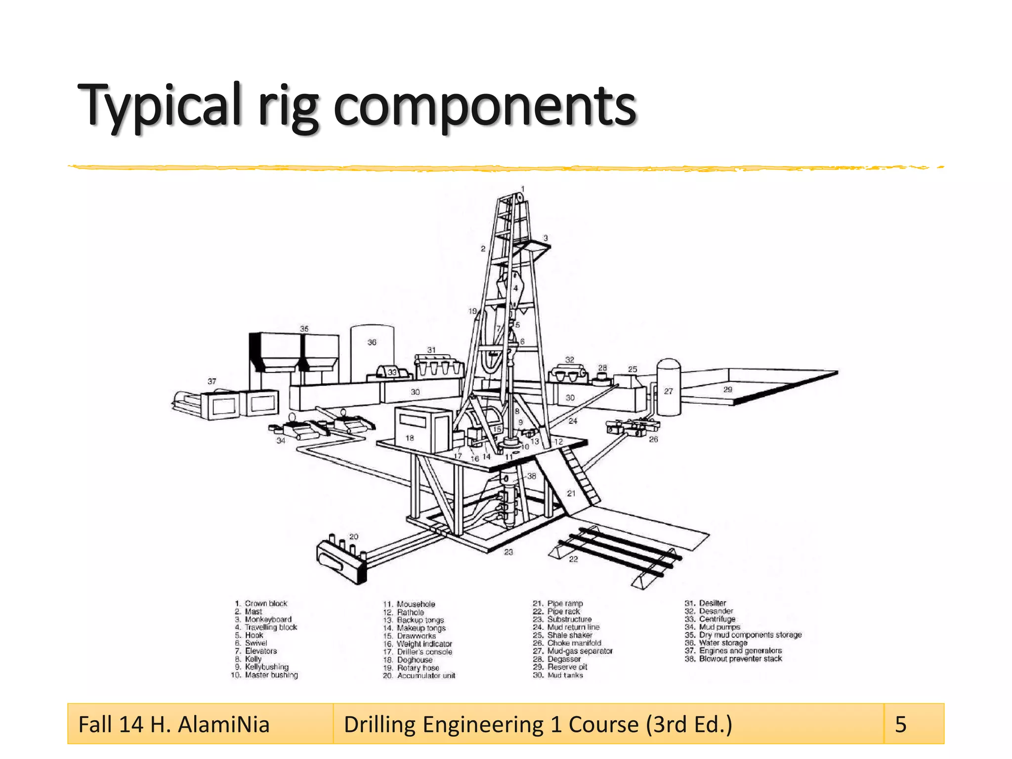
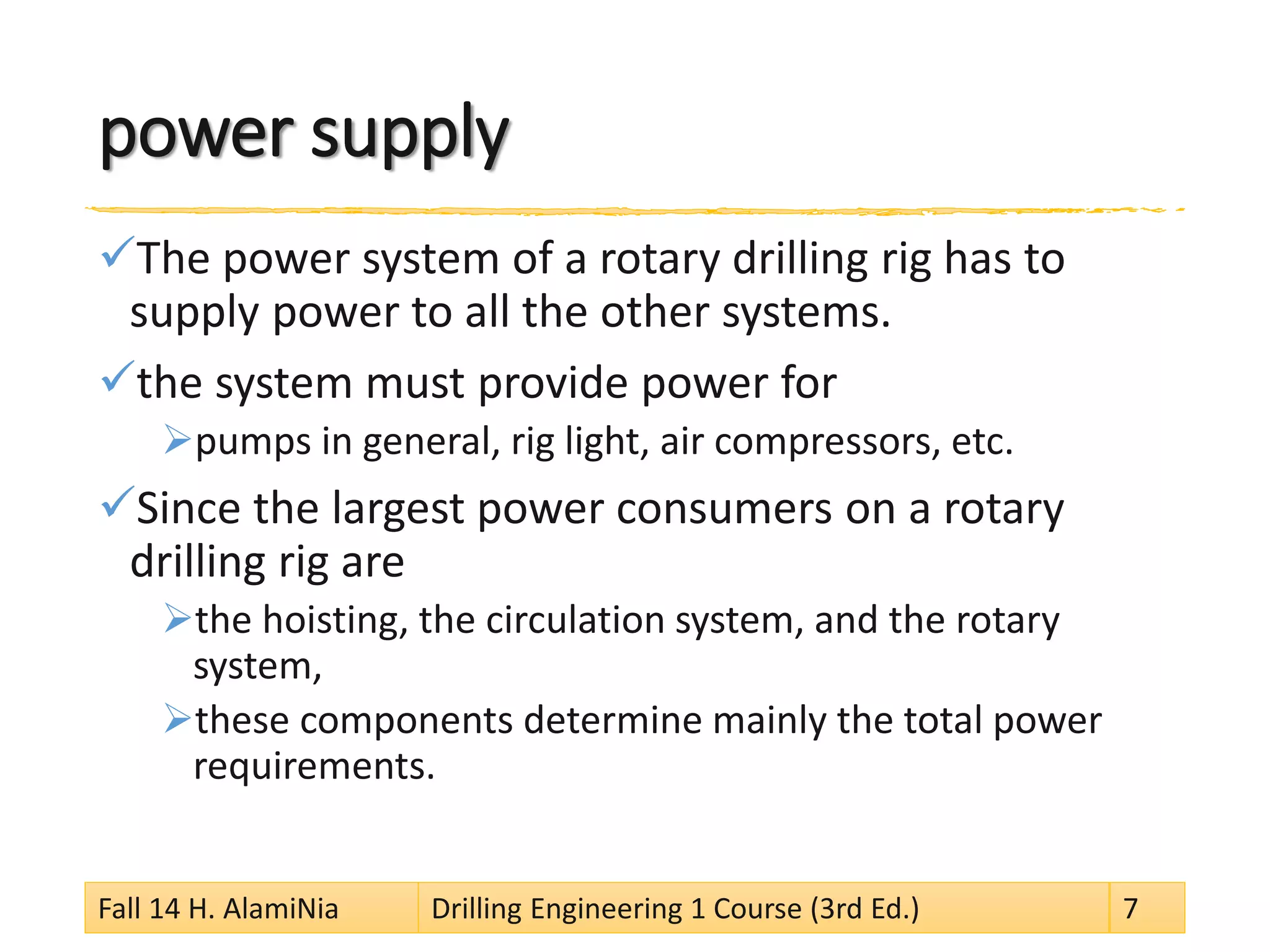
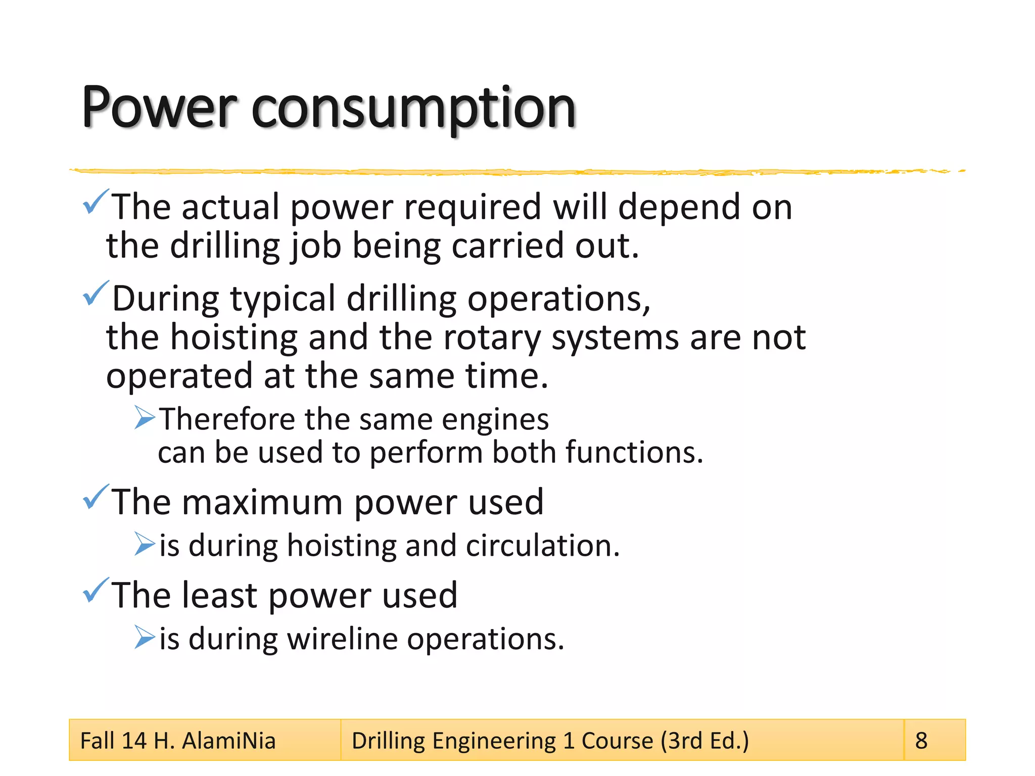
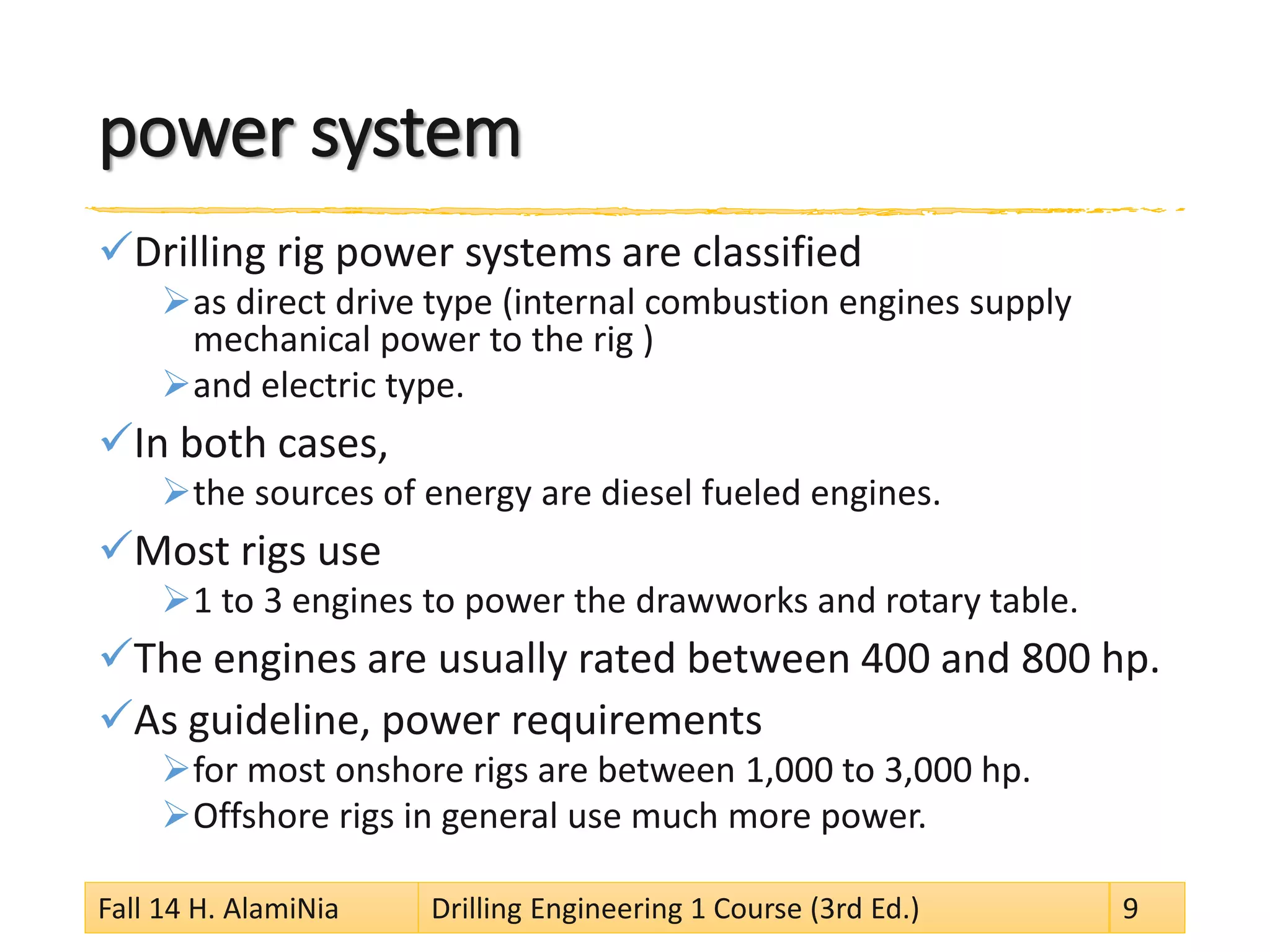
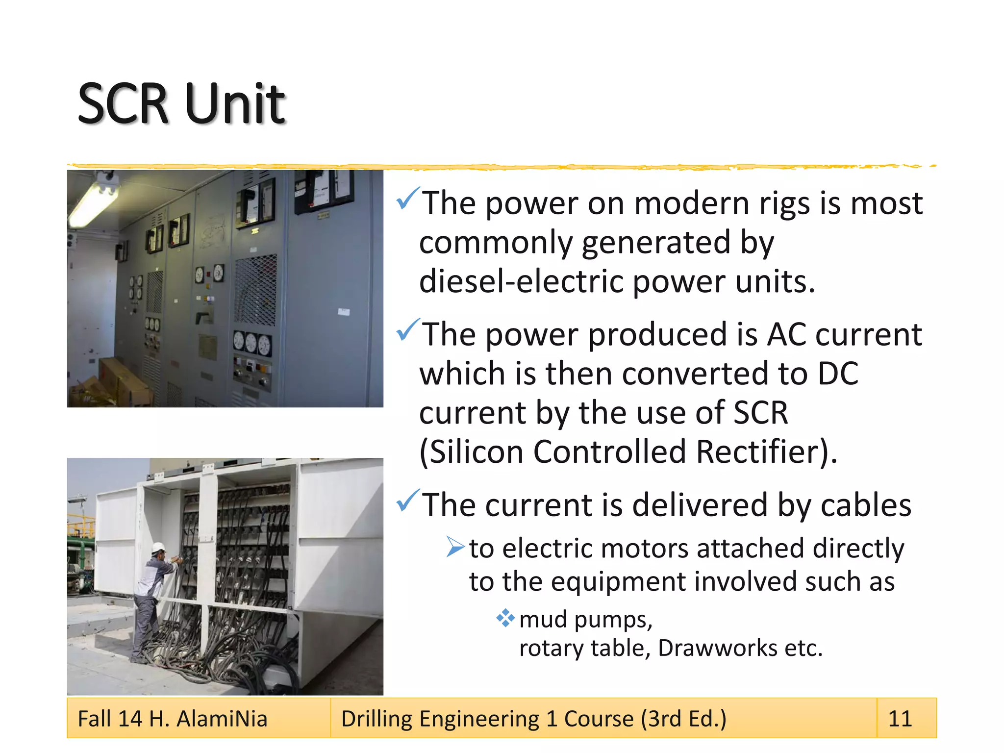
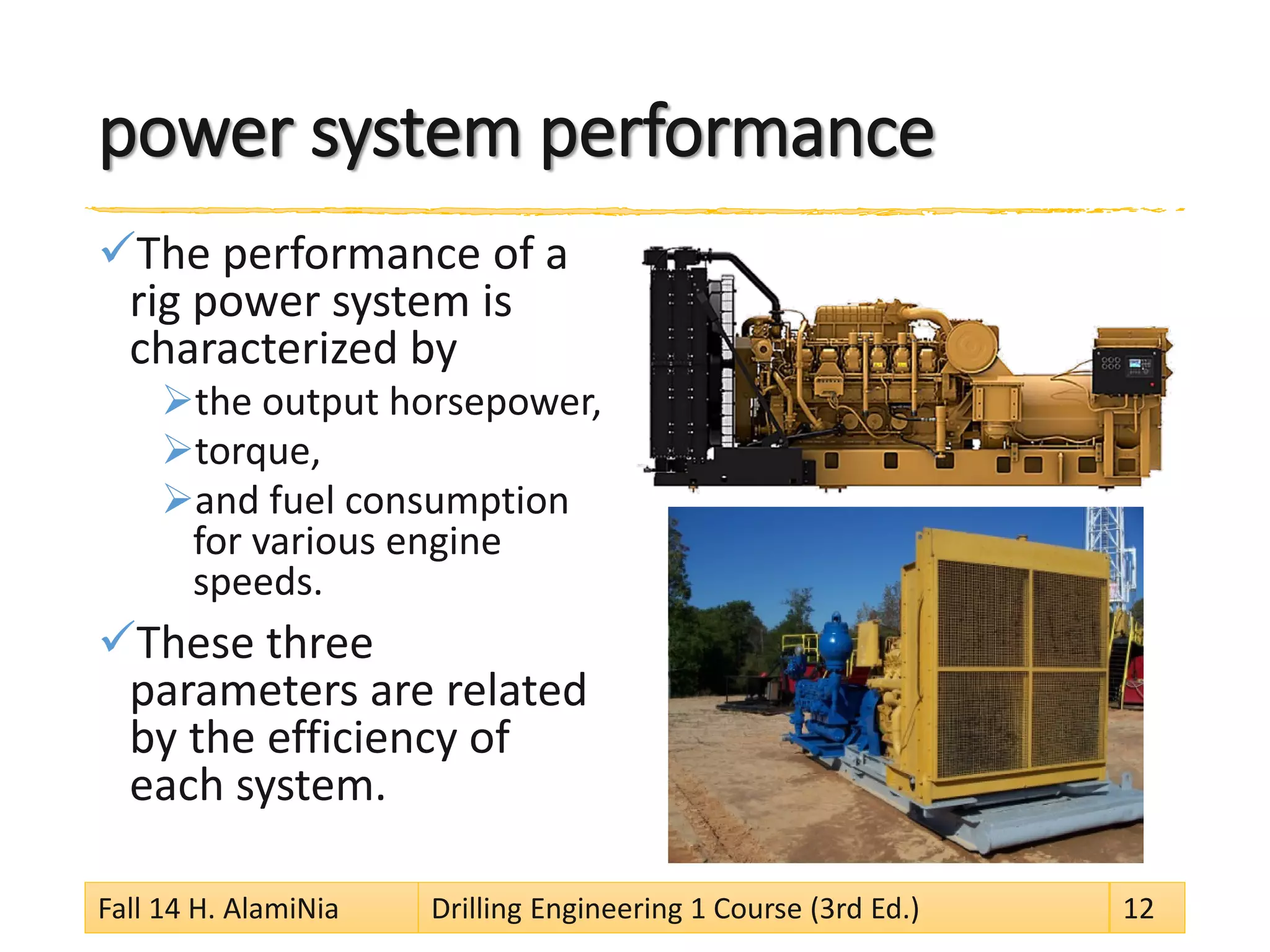
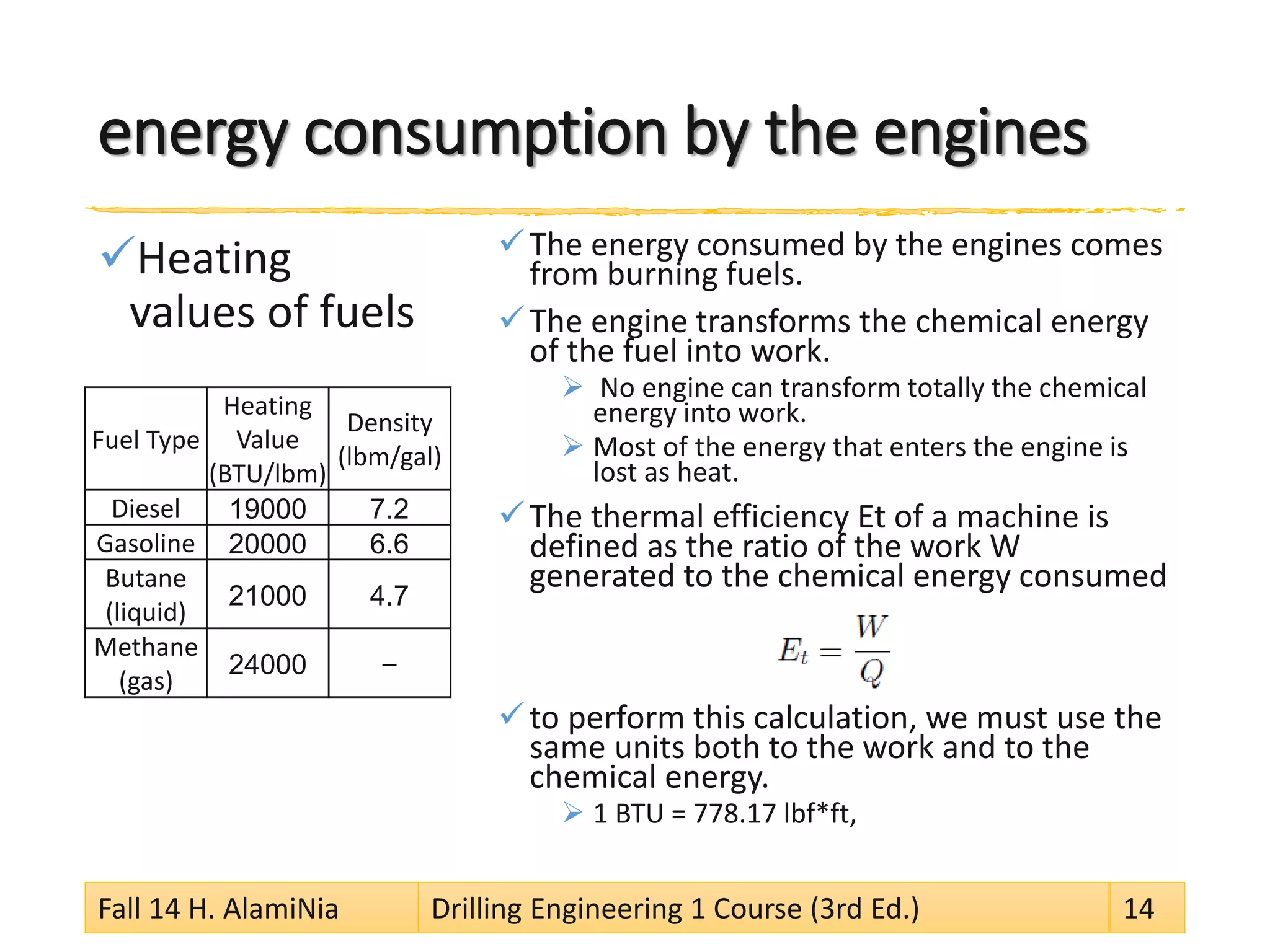
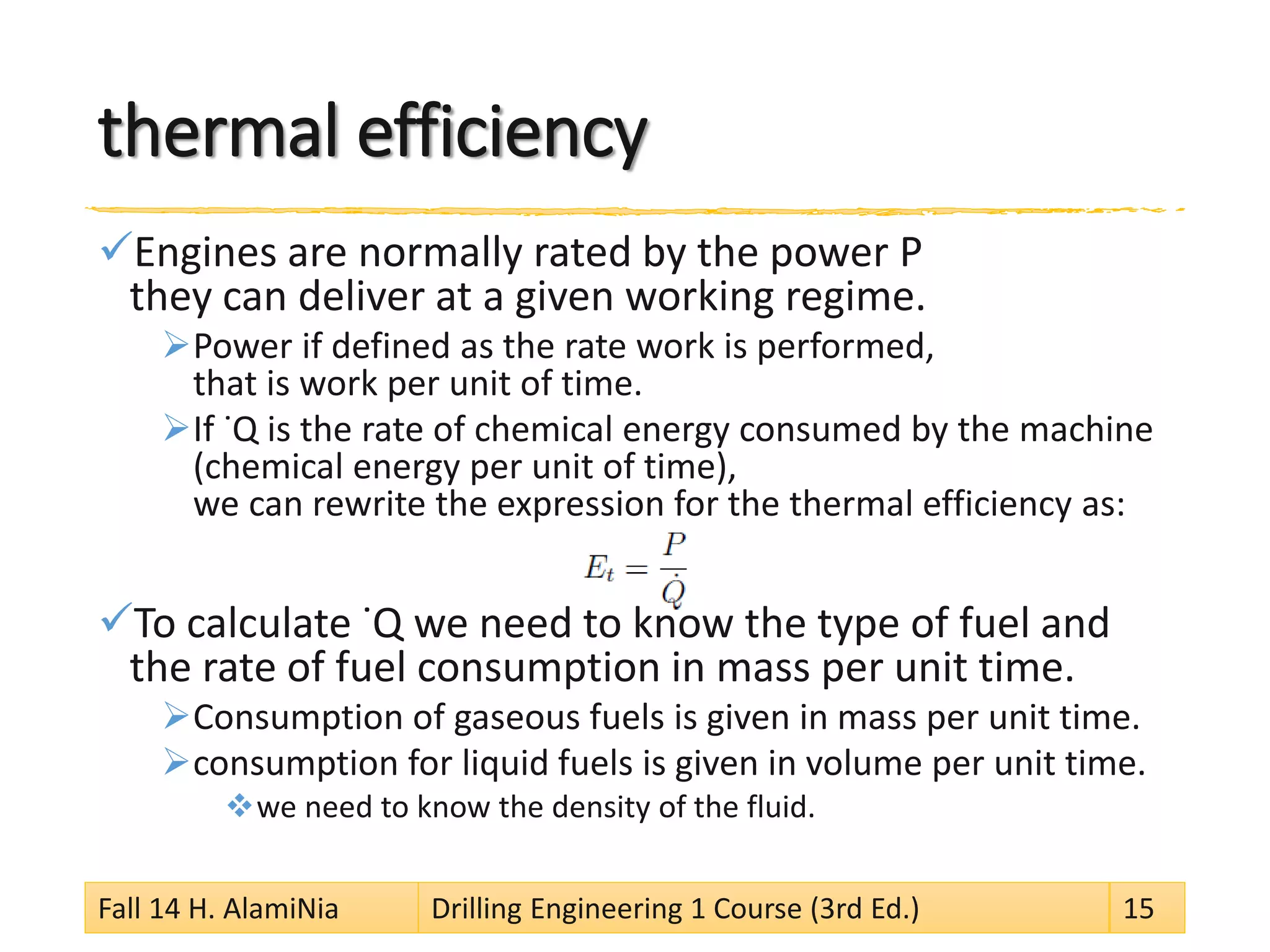
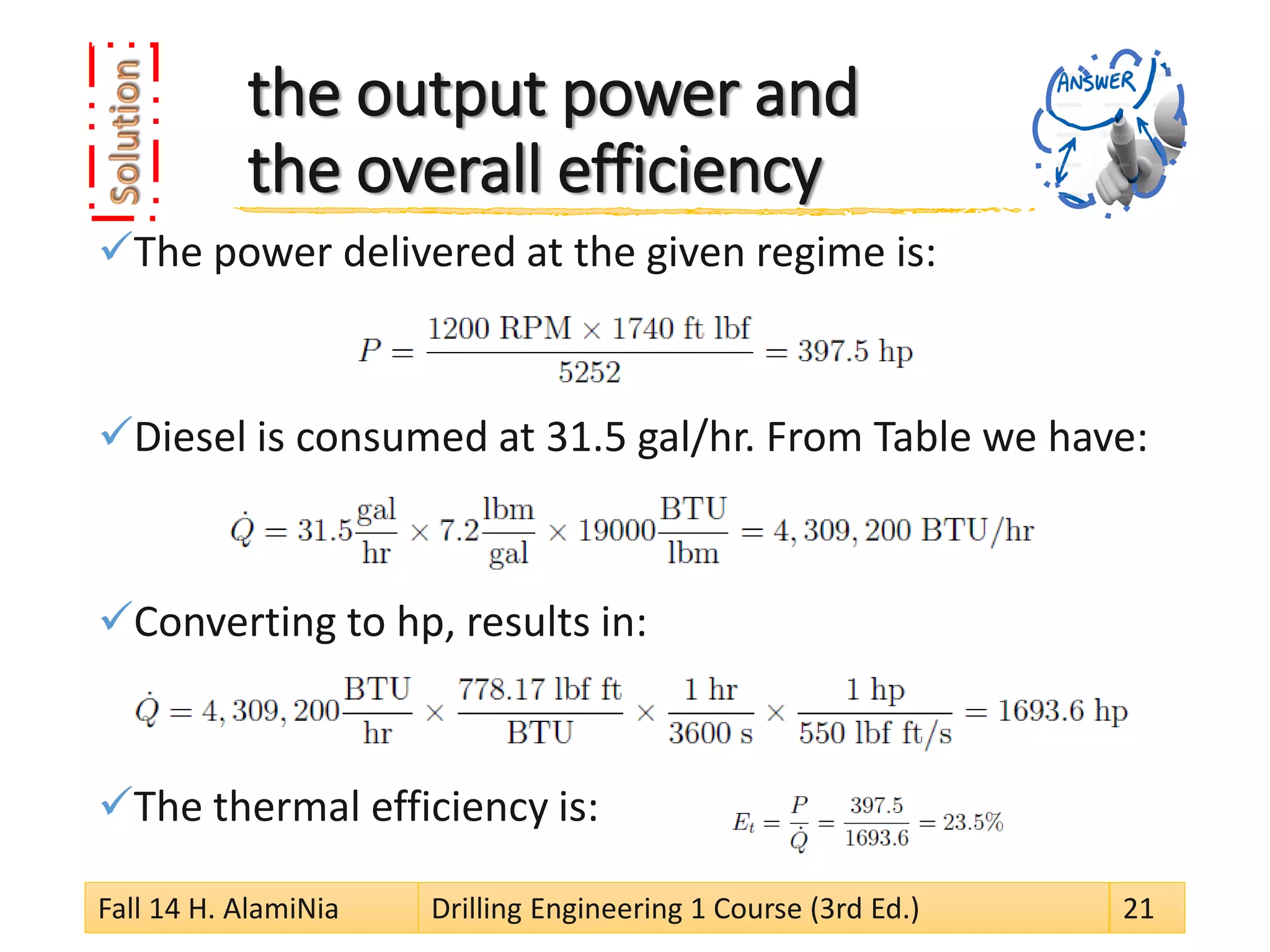
This document discusses the key systems of a rotary drilling rig, including the power system. It explains that the power system provides power to all other rig systems, including hoisting, circulation, and rotary systems. Diesel engines are typically used to power the drawworks and rotary table. The document discusses power requirements, classifications of power systems, power supply components, and calculations for determining output power and efficiency.
The second presentation of a series of presentations on Operations Geology. Very basic, just to introduce beginners to operations geology. I hope the end users will find this and the following presentations very helpful.
This course describe different systems of petroleum drilling rig (Hoisting system, Rotary System,Circulation system,Power system, BOP system and Monitoring system) and provide insight of individual components.
Hi,friend,
This presentation will give some effectiveness for entry level drilling engineers!
Thanks and Best regards,
Myo Min Htet
MPRL E&P Pte Ltd.
+95933336767
myominhtetz2012@gmail.com
DRILLING: It is defined as art & science of making a hole in an object.
OIL & GAS WELL DRILLING: It is an art & science of drilling a hole in the earth crust down to a desired depth in search / extraction of natural gas or oil(petroleum)
Investigating The Performance of A Steam Power PlantIJMERJOURNAL
ABSTRACT: The performance analysis of Shobra El-Khima power plant in Cairo, Egypt is presented based on energy and exergy analysis to determine the causes , the sites with high exergy destruction , losses and the possibilities of improving the plant performance. The performance of the plant was evaluated at different loads (Full, 75% and, 50 %). The calculated thermal efficiency based on the heat added to the steam was found to be 41.9 %, 41.7 %, 43.9% , while the exergetic efficiency of the power cycle was found to be 44.8%, 45.5% and 48.8% at max, 75% and, 50 % load respectively. The condenser was found to have the largest energy losses where (54.3%, 55.1% and 56.3% at max, 75% and, 50 % load respectively) of the added energy to the steam is lost to the environment. The maximum exergy destruction was found to be in the turbine where the percentage of the exergy destruction was found to be (42%, 59% and 46.1% at max, 75% and, 50 % load respectively). The pump was found to have the minimum exergy destruction. It was also found that the exergy destruction in feed water heaters and in the condenser together represents the maximum exergy destruction in the plant (about 52%). This means that the irreversibilities in the heat transfer devices in the plant have a significant role on the exergy destruction. So, it is thought that the improvement in the power plant will be limited due to the heat transfer devices.
Power plant engineering unit 3 notes by Varun Pratap SinghVarun Pratap Singh
Download Link: https://sites.google.com/view/varunpratapsingh/teaching-engagements (Copy URL)
Unit-3
Diesel power plant
General layout, performance of diesel engine, fuel system, lubrication system, air intake and admission system, supercharging system, exhaust system, diesel plant operation and efficiency, heat balance.
Gas turbine power plant
Elements of gas turbine power plants, Gas turbine fuels, cogeneration, auxiliary systems such as fuel, controls and lubrication, operation and maintenance, Combined cycle power plants.
Comparison of Differential Evolution and Particle Swarm Optimization for Opti...IOSRJEEE
This paper proposes an optimization model for the selection of turbines in order to improve the power generation potential in a Hydro Power Plant. The thermal, electrical and mechanical stresses that occur over time on the turbine affect the efficiency of the generating unit. The mathematical formulation for this problem emanates a non-linear programming problem which is therefore solved using Particle Swarm Optimization and Differential Evolution optimizing techniques. These two algorithms are then compared and the results are validated in Dot Net. The Dot Net framework is used due to its extensive security, enhanced usability and flexibility. These optimization techniques are implemented in a case study which is carried out in Murudeshwar Small Hydro Power Plant located in Narayanpur, Bijapur District, India.
Cosmetic shop management system project report.pdfKamal Acharya
Buying new cosmetic products is difficult. It can even be scary for those who have sensitive skin and are prone to skin trouble. The information needed to alleviate this problem is on the back of each product, but it's thought to interpret those ingredient lists unless you have a background in chemistry.
Instead of buying and hoping for the best, we can use data science to help us predict which products may be good fits for us. It includes various function programs to do the above mentioned tasks.
Data file handling has been effectively used in the program.
The automated cosmetic shop management system should deal with the automation of general workflow and administration process of the shop. The main processes of the system focus on customer's request where the system is able to search the most appropriate products and deliver it to the customers. It should help the employees to quickly identify the list of cosmetic product that have reached the minimum quantity and also keep a track of expired date for each cosmetic product. It should help the employees to find the rack number in which the product is placed.It is also Faster and more efficient way.
Hierarchical Digital Twin of a Naval Power SystemKerry Sado
A hierarchical digital twin of a Naval DC power system has been developed and experimentally verified. Similar to other state-of-the-art digital twins, this technology creates a digital replica of the physical system executed in real-time or faster, which can modify hardware controls. However, its advantage stems from distributing computational efforts by utilizing a hierarchical structure composed of lower-level digital twin blocks and a higher-level system digital twin. Each digital twin block is associated with a physical subsystem of the hardware and communicates with a singular system digital twin, which creates a system-level response. By extracting information from each level of the hierarchy, power system controls of the hardware were reconfigured autonomously. This hierarchical digital twin development offers several advantages over other digital twins, particularly in the field of naval power systems. The hierarchical structure allows for greater computational efficiency and scalability while the ability to autonomously reconfigure hardware controls offers increased flexibility and responsiveness. The hierarchical decomposition and models utilized were well aligned with the physical twin, as indicated by the maximum deviations between the developed digital twin hierarchy and the hardware.
Welcome to WIPAC Monthly the magazine brought to you by the LinkedIn Group Water Industry Process Automation & Control.
In this month's edition, along with this month's industry news to celebrate the 13 years since the group was created we have articles including
A case study of the used of Advanced Process Control at the Wastewater Treatment works at Lleida in Spain
A look back on an article on smart wastewater networks in order to see how the industry has measured up in the interim around the adoption of Digital Transformation in the Water Industry.
Industrial Training at Shahjalal Fertilizer Company Limited (SFCL)MdTanvirMahtab2
This presentation is about the working procedure of Shahjalal Fertilizer Company Limited (SFCL). A Govt. owned Company of Bangladesh Chemical Industries Corporation under Ministry of Industries.
4. rig systems
For all rigs, the depth of the planned well determines basic rig requirements. The most important rig systems are:
Power system,
Hoisting system,
Drilling fluid circulation system,
Rotary system,
Derrick and substructure,
Well control system,
Well monitoring system
Fall 14 H. AlamiNia Drilling Engineering 1 Course (3rd Ed.) 4
7. power supply
The power system of a rotary drilling rig has to supply power to all the other systems.
the system must provide power for
pumps in general, rig light, air compressors, etc.
Since the largest power consumers on a rotary drilling rig are
the hoisting, the circulation system, and the rotary system,
these components determine mainly the total power requirements. Fall 14 H. AlamiNia Drilling Engineering 1 Course (3rd Ed.) 7
8. Power consumption
The actual power required will depend on the drilling job being carried out.
During typical drilling operations, the hoisting and the rotary systems are not operated at the same time.
Therefore the same engines can be used to perform both functions.
The maximum power used
is during hoisting and circulation.
The least power used
is during wireline operations.
Fall 14 H. AlamiNia Drilling Engineering 1 Course (3rd Ed.) 8
9. power system
Drilling rig power systems are classified
as direct drive type (internal combustion engines supply mechanical power to the rig )
and electric type.
In both cases,
the sources of energy are diesel fueled engines.
Most rigs use
1 to 3 engines to power the drawworks and rotary table.
The engines are usually rated between 400 and 800 hp.
As guideline, power requirements
for most onshore rigs are between 1,000 to 3,000 hp.
Offshore rigs in general use much more power.
Fall 14 H. AlamiNia Drilling Engineering 1 Course (3rd Ed.) 9
10. Sample of a land rig power supply
Fall 14 H. AlamiNia Drilling Engineering 1 Course (3rd Ed.) 10
11. SCR Unit
The power on modern rigs is most commonly generated by diesel-electric power units.
The power produced is AC current which is then converted to DC current by the use of SCR (Silicon Controlled Rectifier).
The current is delivered by cables
to electric motors attached directly to the equipment involved such as
mud pumps, rotary table, Drawworks etc.
Fall 14 H. AlamiNia Drilling Engineering 1 Course (3rd Ed.) 11
12. power system performance
The performance of a rig power system is characterized by
the output horsepower,
torque,
and fuel consumption for various engine speeds.
These three parameters are related by the efficiency of each system.
Fall 14 H. AlamiNia Drilling Engineering 1 Course (3rd Ed.) 12
13.
14. energy consumption by the engines
Heating values of fuels
The energy consumed by the engines comes from burning fuels.
The engine transforms the chemical energy of the fuel into work.
No engine can transform totally the chemical energy into work.
Most of the energy that enters the engine is lost as heat.
The thermal efficiency Et of a machine is defined as the ratio of the work W generated to the chemical energy consumed
to perform this calculation, we must use the same units both to the work and to the chemical energy.
1 BTU = 778.17 lbf*ft,
Fall 14 H. AlamiNia Drilling Engineering 1 Course (3rd Ed.) 14
Fuel Type
Heating Value(BTU/lbm)
Density(lbm/gal)
Diesel
19000
7.2
Gasoline
20000
6.6
Butane (liquid)
21000
4.7
Methane (gas)
24000
–
15. thermal efficiency
Engines are normally rated by the power P they can deliver at a given working regime.
Power if defined as the rate work is performed, that is work per unit of time.
If ˙Q is the rate of chemical energy consumed by the machine (chemical energy per unit of time), we can rewrite the expression for the thermal efficiency as:
To calculate ˙Q we need to know the type of fuel and the rate of fuel consumption in mass per unit time.
Consumption of gaseous fuels is given in mass per unit time.
consumption for liquid fuels is given in volume per unit time.
we need to know the density of the fluid.
Fall 14 H. AlamiNia Drilling Engineering 1 Course (3rd Ed.) 15
16. output power
A system produces mechanical work when the sole result of the process could be the raising of a weight (most time limited by its efficiency).
P is power, and v the velocity (assuming F constant).
When a rotating machine is operating (for example, an internal combustion engine or an electrical motor),
we cannot measure its power,
but we can measure its rotating speed (normally in RPM) and the torque at the shaft.
This is normally performed in a machine called dynamometer. Fall 14 H. AlamiNia Drilling Engineering 1 Course (3rd Ed.) 16
17. output power
The expression relating power to angular velocity and torque is:
ω is the angular velocity (in radians per unit of time)
T is the torque.
A common unit of power is the hp (horse power).
One hp is the power required to raise a weight of 33,000 lbf by one foot in one minute:
Fall 14 H. AlamiNia Drilling Engineering 1 Course (3rd Ed.) 17
18. output power
For T in ft lbf and N in RPM we have:
that is
Fall 14 H. AlamiNia Drilling Engineering 1 Course (3rd Ed.) 18
19. mechanical horsepower Correction
When the rig is operated at environments with non–standard temperatures (85F=29C) or at high altitudes, the mechanical horsepower requirements have to be corrected.
The correction should follow the American Petroleum Institute (API) standard 7B-llC:
Deduction of 3% of the standard brake horsepower for each 1000 ft of altitude above mean sea level.
Deduction of 1% of the standard brake horsepower for each 10F rise or fall in temperature above or below 85F.
Fall 14 H. AlamiNia Drilling Engineering 1 Course (3rd Ed.) 19
20. Calculation of the output power and the overall efficiency
A diesel engine gives an output torque of 1740 ft lbf at an engine speed of 1200 RPM.
If the fuel consumption rate was 31.5 gal/hr,
what is the output power and
the overall efficiency of the engine?
Fall 14 H. AlamiNia Drilling Engineering 1 Course (3rd Ed.) 20
21. the output power and the overall efficiency
The power delivered at the given regime is:
Diesel is consumed at 31.5 gal/hr. From Table we have:
Converting to hp, results in:
The thermal efficiency is:
Fall 14 H. AlamiNia Drilling Engineering 1 Course (3rd Ed.) 21
22. 1.(CDF) Jorge H.B. Sampaio Jr. “Drilling Engineering Fundamentals.” Master of Petroleum Engineering. Curtin University of Technology, 2007.
Chapter 2
2.(WEC) Rabia, Hussain. Well Engineering & Construction. Entrac Consulting Limited, 2002.
Chapter 16