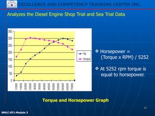
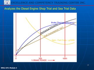
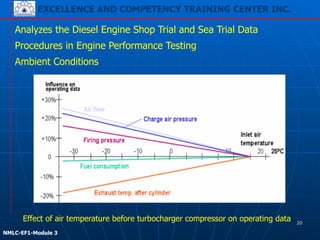
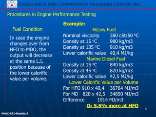
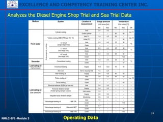
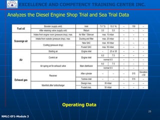
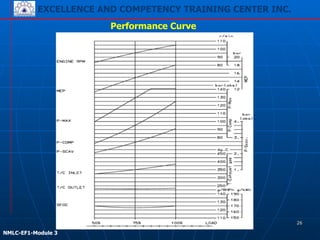
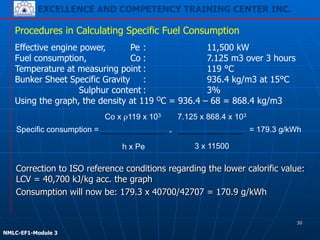
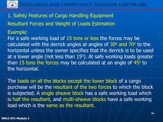
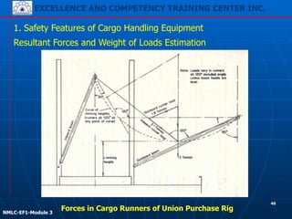
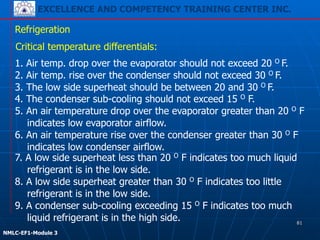
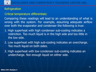
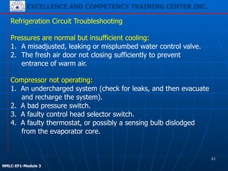
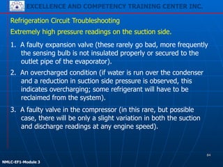
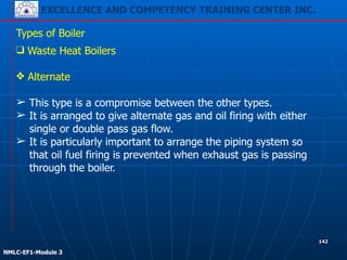
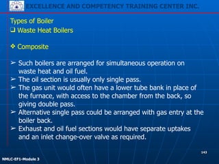
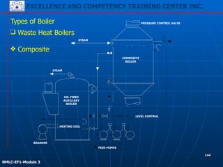
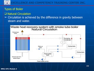
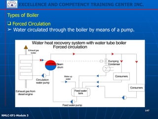
EXCELLENCE AND COMPETENCY TRAINING CENTER INC.
!
!
NMLC-EF1-Module 3
Function 1:
Marine Engineering at the
Management Level
EXCELLENCE AND COMPETENCY TRAINING CENTER INC.
!
!
NMLC-EF1-Module 1
1
EXCELLENCE AND COMPETENCY TRAINING CENTER INC.
!
!
NMLC-EF1-Module 3
EXCELLENCE AND COMPETENCY TRAINING CENTER INC.
COVERAGES:
Module 1 – Manage the operation of propulsion plant machinery
Module 2 – Plan and schedule operations
Module 3 – Operation surveillance, performance
assessment and maintaining safety of
propulsion plant and auxiliary machinery
Module 4 – Manage fuel, lubrication and ballast operations
!
!
NMLC-EF1-Module 1
2
EXCELLENCE AND COMPETENCY TRAINING CENTER INC.
!
!
NMLC-EF1-Module 3
Function 1: Marine Engineering at the Management Level
EXCELLENCE AND COMPETENCY TRAINING CENTER INC.
!
!
NMLC-EF1-Module 1
3
EXCELLENCE AND COMPETENCY TRAINING CENTER INC.
!
!
NMLC-EF1-Module 3
Function 1: Marine Engineering at the Management Level
1.1.2 Operating Principles of Ship Power
Installations
!!Module 1
4
EXCELLENCE AND COMPETENCY TRAINING CENTER INC.
!
!
NMLC-EF1-Module 3
❑ The prefix "brake" refers to where the power is measured: at
the engine's output shaft, as on an engine dynamometer.
Analyzes the Diesel Engine Shop Trial and Sea Trial Data
Brake Horsepower (BHP)
❑ Measure of an engine's horsepower without the loss in power
caused by the gearbox, generator, differential, water pump and
other auxiliaries.
❑ The term "brake" refers to the use of a band brake to measure
torque during the test (which is multiplied by the engine speed
in revs/sec and circumference of the band to give the power).
5
EXCELLENCE AND COMPETENCY TRAINING CENTER INC.
!
!
NMLC-EF1-Module 3
1. An absorbing dynamometer acts as a load that is driven by the prime
mover that is under test.
2. The dynamometer must be able to operate at any speed, and load
the prime mover to any level of torque that the test requires.
3. A dynamometer is usually equipped with some means of measuring
the operating torque and speed.
4. The dynamometer must absorb the power developed by the prime
mover. The power absorbed by the dynamometer must generally be
dissipated to the ambient air or transferred to cooling water.
Analyzes the Diesel Engine Shop Trial and Sea Trial Data
Dynamometer
6
EXCELLENCE AND COMPETENCY TRAINING CENTER INC.
!
!
NMLC-EF1-Module 3
❑ It is calculated from the pressures developed in the cylinders,
measured by a device called an engine indicator
– hence indicated horsepower.
Analyzes the Diesel Engine Shop Trial and Sea Trial Data
Indicated Horsepower (IHP)
❑ It is the theoretical power of a reciprocating engine assuming
that it is completely efficient in converting the energy contained
in the expanding gases in the cylinders.
IHP = (P x L x A x N)/33,000 ft-lbs/min.
7
EXCELLENCE AND COMPETENCY TRAINING CENTER INC.
!
!
NMLC-EF1-Module 3
❑ The Horsepower is measure of mechanical power. The power
of a steam engine is expressed as indicated horsepower (IHP),
the work of the steam in the cylinder, or nominal horsepower
(NHP), an expression of power derived by formula.
Analyzes the Diesel Engine Shop Trial and Sea Trial Data
Indicated Horsepower (IHP) of Turbines
❑ Steam turbines are measured by shaft horsepower (SHP).
8
EXCELLENCE AND COMPETENCY TRAINING CENTER INC.
!
!
NMLC-EF1-Module 3
❑ Is the average (mean) pressure which, if imposed on the
pistons uniformly from the top to the bottom of each power
stroke, would produce the measured (brake) power output.
Analyzes the Diesel Engine Shop Trial and Sea Trial Data
Brake Mean Effective Pressure (BMEP)
9
EXCELLENCE AND COMPETENCY TRAINING CENTER INC.
!
!
NMLC-EF1-Module 3
Shaft power
Mechanical efficiency = --------------------------
Indicated power
Analyzes the Diesel Engine Shop Trial and Sea Trial Data
Mechanical Efficiency - the power lost as a result of friction
between the moving parts of the engine results in the difference
between shaft and indicated power. The ratio of shaft power to
indicated power for an engine is the “mechanical efficiency”.
Thermal Efficiency - is the measure of the efficiency and
completeness of combustion of the fuel, or, more specifically, the
ratio of the output or work done by the working substance in the
cylinder in a given time to the input or heat energy of the fuel
supplied during the same time.
10
EXCELLENCE AND COMPETENCY TRAINING CENTER INC.
!
!
NMLC-EF1-Module 3
Analyzes the Diesel Engine Shop Trial and Sea Trial Data
R3
R4 R2
R1
Engine
layout
field
Engine-MCR
Speed
Power
The output of the engines are
defined by the power/speed
rating points R1, R2, R3, and
R4. R1 is the nominal maximum
continuous rating (MCR = the
o u t p u t w h a t t h e e n g i n e
continuously may run).
Any power and speed in the
respective engine layout field
m ay b e s e l e c t e d a s t h e
Contract-MCR (CMCR).
Speed and Power Graph
11
EXCELLENCE AND COMPETENCY TRAINING CENTER INC.
!
!
NMLC-EF1-Module 3
Analyzes the Diesel Engine Shop Trial and Sea Trial Data
❖ Horsepower =
(Torque x RPM) / 5252
!
❖ At 5252 rpm torque is
equal to horsepower.
Torque and Horsepower Graph
12
EXCELLENCE AND COMPETENCY TRAINING CENTER INC.
!
!
NMLC-EF1-Module 3
Analyzes the Diesel Engine Shop Trial and Sea Trial Data
% BRAKE POWER
0 50% 100%
Spec. Fuel Cons.: g/kWh
Brake Thermal Efficiency
13
EXCELLENCE AND COMPETENCY TRAINING CENTER INC.
!
!
NMLC-EF1-Module 3
❑ Main engines will have the optimum designed maximum
efficiency and so the minimum specific fuel consumption at
full load or close to this.
Analyzes the Diesel Engine Shop Trial and Sea Trial Data
Fuel Consumption
❑ In practice the fuel consumption will be higher because of the
more unfavorable ambient conditions, lower heat value of the
fuel and wear of engine components.
❑ Also when the engine is not running in the optimum operating
point this value will be higher.
❑ Generator engines on board ships may have their optimum at
70% load as these engines are probably averaging this load in
operation.
14
EXCELLENCE AND COMPETENCY TRAINING CENTER INC.
!
!
NMLC-EF1-Module 3
❑ As can be seen in the figure the fuel consumption in kg/s
increases with the load but in this example the design has
been made in such a way that the overall efficiency is highest
at 100% load and so the specific fuel consumption is lowest at
that load.
Analyzes the Diesel Engine Shop Trial and Sea Trial Data
Performance Evaluation
❑ In the performance curve for a certain engine the load at
which the engine has the lowest fuel consumption can be
found.
❑ The optimizing point is the rating at which the turbocharger is
matched and at which the engine timing and compression
ratio are adjusted.
❑ The performance curve will show where this point is located.
15
EXCELLENCE AND COMPETENCY TRAINING CENTER INC.
!
!
NMLC-EF1-Module 3
But also the following:
!
- output,
- ambient conditions,
- fuel condition and
- external conditions should be taken into account.
Analyzes the Diesel Engine Shop Trial and Sea Trial Data
Procedures in Engine Performance Testing
When evaluating the running data it should be realized that not
only the condition of the engine may give a change of these values
(compared to the ones mentioned in the test bed protocols).
16
EXCELLENCE AND COMPETENCY TRAINING CENTER INC.
!
!
NMLC-EF1-Module 3
❑ The engine has been designed for a certain maximum output
at a certain rpm, what gives a certain MEP (Pe = c x mep x n).
Analyzes the Diesel Engine Shop Trial and Sea Trial Data
Procedures in Engine Performance Testing
Output
❑ The operating data depend mainly on the output of the engine.
❑ During the test run the operating data are noted down on
different loads and very often the main data are made into a
graph.
❑ Overloading for a longer time (most manufacturers accept
10% overload one hour every 24 hours, but this should be an
exemption and no rule) should be avoided, since the higher
temperatures and pressures may exceed the permissible limit
and will damage the engine.
17
EXCELLENCE AND COMPETENCY TRAINING CENTER INC.
!
!
NMLC-EF1-Module 3
❑ The output can be read from the torque meter (if installed), be
calculated from diagrams or be estimated by reading the fuel
rack position (or L.I.), the turbocharger rpm, the air receiver
pressure and the combustion pressure.
Analyzes the Diesel Engine Shop Trial and Sea Trial Data
Procedures in Engine Performance Testing
Output
18
EXCELLENCE AND COMPETENCY TRAINING CENTER INC.
!
!
NMLC-EF1-Module 3
The ambient conditions will affect the running data quite a lot and
should be known when judging these data. The design output is
available up to the following tropical conditions (acc. to ISO):
blower inlet temperature 45 oC
blower inlet pressure 1000 mbar
seawater temperature 32 oC
Analyzes the Diesel Engine Shop Trial and Sea Trial Data
Procedures in Engine Performance Testing
In case the temperatures are higher and/or the pressure is lower
the engine should be de-rated to a lower output. If the blower inlet
temperature will rise the following parameters will change:
airflow will decrease
charge air pressure will decrease
firing pressure will decrease
exhaust gas temperature will rise
fuel consumption will increase.
Ambient Conditions
19
EXCELLENCE AND COMPETENCY TRAINING CENTER INC.
!
!
NMLC-EF1-Module 3
Ambient Conditions
Analyzes the Diesel Engine Shop Trial and Sea Trial Data
Procedures in Engine Performance Testing
Effect of air temperature before turbocharger compressor on operating data 20
EXCELLENCE AND COMPETENCY TRAINING CENTER INC.
!
!
NMLC-EF1-Module 3
Procedures in Engine Performance Testing
Example:
Heavy Fuel
Nominal viscosity 380 cSt/50 oC
Density at 15 oC 980 kg/m3
Density at 135 oC 910 kg/m3
Lower calorific value 40,4 MJ/kg
Marine Diesel Fuel
Density at 15 oC 840 kg/m3
Density at 45 oC 820 kg/m3
Lower calorific value 42,5 MJ/kg
Lower Calorific Value per Volume
For HFO 910 x 40,4 36764 MJ/m3
For MD 820 x 42,5 34850 MJ/m3
Difference 1914 MJ/m3
Or 5.5% more at HFO
In case the engine
changes over from
HFO to MDO, the
output will decrease
at the same L.I.
position because of
the lower calorific
value per volume.
Fuel Condition
21
EXCELLENCE AND COMPETENCY TRAINING CENTER INC.
!
!
NMLC-EF1-Module 3
Procedures in Engine Performance Testing
1. Dirty air filter on the turbo charger
2. Fouled or damaged turbocharger
3. Dirty air cooler on suction side Dirty air cooler on water side
4. Insufficient or too high temperature cooling water for the air
cooler
5. Partly blocked scavenging ports
6. Dirty pipes in the economizer (exhaust gas boiler)
7. Too low pressure (too less overpressure) in the engine room
External Conditions
❑ Sufficient air to the engine is essential for a good performance
of the engine.
❑ Less air will cause a worse combustion resulting in smoke,
higher exhaust gas temperatures, higher fuel consumption and
fouling.
Possible reasons for this air reduction may be:
22
EXCELLENCE AND COMPETENCY TRAINING CENTER INC.
!
!
NMLC-EF1-Module 3
Procedures in Engine Performance Testing
❑ All these conditions have to be taken into consideration when
judging running data. Very often it appears that a deviation of
one reading is not caused by one reason, but by a number of
causes.
❑ Changing the amount of fuel to the different cylinders to try to
get the exhaust gas temperatures equal is not the best
solution; an unbalanced engine is the result.
❑ If an engine is not well maintained it may be so that a high
exhaust gas temperature is caused by a combination of a
worn injector, a not correct timing of the fuel pump, dirty air
cooler, a liner with too much wear and a partly blocked
exhaust gas boiler. In these cases it is hard to find the main
reason.
23
EXCELLENCE AND COMPETENCY TRAINING CENTER INC.
!
!
NMLC-EF1-Module 3
Analyzes the Diesel Engine Shop Trial and Sea Trial Data
Operating Data
24
EXCELLENCE AND COMPETENCY TRAINING CENTER INC.
!
!
NMLC-EF1-Module 3
Analyzes the Diesel Engine Shop Trial and Sea Trial Data
Operating Data
25
EXCELLENCE AND COMPETENCY TRAINING CENTER INC.
!
!
NMLC-EF1-Module 3
Performance Curve
26
EXCELLENCE AND COMPETENCY TRAINING CENTER INC.
!
!
NMLC-EF1-Module 3
Procedures in Calculating Specific Fuel Consumption
- If a flow meter is used a minimum of 1 hour is
recommended.
❑ Calculation of the specific fuel oil consumption requires that
the engine output and the consumed fuel oil amount are
known for a certain period of time. The output can be
calculated from the indicator diagrams.
❑ The oil amount should be measured during a suitable long
period to achieve a reasonable measuring accuracy.
❑ The consumed fuel can be measured in the following way:
- In case a day tank is used, the time for the consumption
of the whole tank content will be suitable.
Always perform the measurements under calm weather conditions.
27
EXCELLENCE AND COMPETENCY TRAINING CENTER INC.
!
!
NMLC-EF1-Module 3
Procedures in Calculating Specific Fuel Consumption
❑ On the bunker sheet the density will be given at 15 °C/60 °F.
The actual density can now be determined by using the curve
on included diagram.
❑ Both methods are measuring the quantity in volume units, it is
necessary to know the oil density to convert it to weight units.
❑ Specific gravity can be determined by means of a hydrometer
immersed in a sample taken at the measuring point, density
can also be calculated on the basis of bunker specifications.
❑ The consumed oil quantity in kg is obtained by multiplying the
measured volume by the density.
28
EXCELLENCE AND COMPETENCY TRAINING CENTER INC.
!
!
NMLC-EF1-Module 3
Procedures in Calculating Specific Fuel Consumption
❑ To determine the LCV of the used fuel (if not given by the oil
company), the included graph may be used.
❑ The corrected fuel consumption can then be calculated by
multiplying the measured consumption by (LCV of the used
fuel/42,707).
❑ The ambient conditions (blower inlet temperature and
pressure and scavenge air coolant temperature) will also
influence the fuel consumption.
❑ To compare the specific fuel consumption for various types of
fuel, allowances must be made for the differences in the lower
calorific value of the fuel concerned.
29
EXCELLENCE AND COMPETENCY TRAINING CENTER INC.
!
!
NMLC-EF1-Module 3
Procedures in Calculating Specific Fuel Consumption
Correction to ISO reference conditions regarding the lower calorific value:
LCV = 40,700 kJ/kg acc. the graph
Consumption will now be: 179.3 x 40700/42707 = 170.9 g/kWh
Specific consumption =
Co x ρ119 x 103
h x Pe
7.125 x 868.4 x 103
3 x 11500
!= = 179.3 g/kWh
Effective engine power, Pe : 11,500 kW
Fuel consumption, Co : 7.125 m3 over 3 hours
Temperature at measuring point : 119 °C
Bunker Sheet Specific Gravity : 936.4 kg/m3 at 15°C

Sulphur content : 3%
Using the graph, the density at 119 OC = 936.4 – 68 = 868.4 kg/m3
30
EXCELLENCE AND COMPETENCY TRAINING CENTER INC.
!
!
NMLC-EF1-Module 3
Procedures in Calculating Specific Cylinder Oil Consumption
❑ Specific cylinder lubricating oil consumption:
!
(1000 x G)/ P = g/kWh (g/BHP/h)
❑ To determine the actual cylinder lubricating oil consumption,
exact time and the revolution counter of the engine must be
recorded at the start and end of the measurement.
❑ The consumed oil quantity is read on the level gauge or flow
meters in liters (liters x density = weight of oil in kg).
❑ To calculate the specific cylinder lubricating oil consumption,
the power output during the test must be known.
G = Cylinder lubricating oil consumption in kg/h.
P = Effective engine power output in kW (HP)
31
EXCELLENCE AND COMPETENCY TRAINING CENTER INC.
!
!
NMLC-EF1-Module 3
32
Operation and Maintenance of Cargo
Handling Equipment and Deck Machinery
EXCELLENCE AND COMPETENCY TRAINING CENTER INC.
!
!
NMLC-EF1-Module 3
33
❑ Safety Features of Cargo Handling Equipment
1. Cargo winches are used with the various derrick systems
arranged for cargo handling.
2. The unit is rated according to the safe working load to be lifted
and usually has a double-speed provision when working at half
load.
3. Spur reduction gearing transfers the motor drive to the barrel
shaft. A warp end may be fitted for operating the derrick
topping lift (the wire which adjusts the derrick height).
4. Manually operated band brakes may be fitted and the drive
motor will have a brake arrange to fail-safe, i.e. it will hold the
load if power fails or the machine stopped.
Cargo Winches
EXCELLENCE AND COMPETENCY TRAINING CENTER INC.
!
!
NMLC-EF1-Module 3
34
❑ Safety Features of Cargo Handling Equipment
Cargo Winches
Patent Derricks
EXCELLENCE AND COMPETENCY TRAINING CENTER INC.
!
!
NMLC-EF1-Module 3
35
❑ Safety Features of Cargo Handling Equipment
Cargo Winches
Swinging Derrick Rig
EXCELLENCE AND COMPETENCY TRAINING CENTER INC.
!
!
NMLC-EF1-Module 3
36
❑ Safety Features of Cargo Handling Equipment
Cargo Winches
Yo-yo Arrangement
EXCELLENCE AND COMPETENCY TRAINING CENTER INC.
!
!
NMLC-EF1-Module 3
37
❑ Safety Features of Cargo Handling Equipment
1. A derrick rig, known as “union purchase”, one derrick is
positioned over the quayside and the other almost vertically
over the hold.
2. Topping wires fix the height of the derricks and stays to the
deck may be used to prevent fore and aft movements.
Union Purchase
EXCELLENCE AND COMPETENCY TRAINING CENTER INC.
!
!
NMLC-EF1-Module 3
38
❑ Safety Features of Cargo Handling Equipment
1. Deck cranes features double
gearing on most designs,
providing a higher speed at
lighter loads.
2. The safe working loads of
cranes is generally of the
order of 10 to 15 tons and
larger cranes are capable to
lift from 30 to 40 tons.
3. Cranes are less effective
with very light loads.
Deck Cranes
EXCELLENCE AND COMPETENCY TRAINING CENTER INC.
!
!
NMLC-EF1-Module 3
39
1. Safety Features of Cargo Handling Equipment
1. Hoist upper limit switch/stop – limits the upward travel of the
boom in order to prevent a two-block condition. Activation of
the limiting device prevents upward motion of the boom and
applies the holding brake.
2. Boom limit switches/stops – installed to ensure that:
a) Maximum boom angle is not exceeded and topping ropes
remain tension.
b) Maximum boom angle is not exceeded so that the angle
between the boom and topping ropes does not exceed
minimum angle.
c) A minimum of 2 ½ turns of rope stays on the topping winch
at all times.
Deck Cranes Safety Devices
EXCELLENCE AND COMPETENCY TRAINING CENTER INC.
!
!
NMLC-EF1-Module 3
40
❑ Safety Features of Cargo Handling Equipment
3. Emergency stop/power off – removes power to all drive motors
and applies holding brakes (can also be activated from a
remote location).
4. Travel warning device – all traveling cranes must be equipped
with a continuously sounding warning device which operates
when the crane is in motion.
5. Loss of power – brakes are applied and crane motion is
stopped.
Deck Cranes Safety Devices
EXCELLENCE AND COMPETENCY TRAINING CENTER INC.
!
!
NMLC-EF1-Module 3
41
❑ Safety Features of Cargo Handling Equipment
The geometry of the derrick
rig will influence the loads
carried by the rig components.
Those dimensions which have
the greatest influence are:
!
1. Length of boom.
2. Distance between boom
heel.
3. Masthead span connection
(height of suspension).
4. The angle at which the
boom is topped.
Resultant Forces and Weight of Loads Estimation
Forces in Single Swinging Derrick
EXCELLENCE AND COMPETENCY TRAINING CENTER INC.
!
!
NMLC-EF1-Module 3
42
❑ Safety Features of Cargo Handling Equipment
1. When the ratio between boom length and height of suspension
is increased the boom thrust will be higher; therefore should a
long boom be required the height of suspension must be
adequate.
2. The angle at which the derrick is topped has no effect on the
axial thrust, but the lead from the cargo purchase often
increases the thrust as it is led parallel to the boom on all
except heavy lifts derricks.
3. Loads carried by the span are dependent on both the ratio of
boom length to height of suspension and the angle at which
the derrick is topped. The span load is greater at a lower angle
to the horizontal, and increases with longer booms for a given
suspension height.
Resultant Forces and Weight of Loads Estimation
EXCELLENCE AND COMPETENCY TRAINING CENTER INC.
!
!
NMLC-EF1-Module 3
43
❑ Safety Features of Cargo Handling Equipment
Resultant Forces and Weight of Loads Estimation
1. To determine these forces simple space and force diagrams may
be drawn and the resultant forces determined to give the
required wire sizes, block and connection safe working loads,
and the thrust experienced by the boom.
!
2. The horizontal and vertical components of the span load and
boom thrust are also used to determine the mast scantlings.
EXCELLENCE AND COMPETENCY TRAINING CENTER INC.
!
!
NMLC-EF1-Module 3
44
1. Safety Features of Cargo Handling Equipment
Example:
For a safe working load of 15 tons or less the forces may be
calculated with the derrick angles at angles of 30o and 70o to the
horizontal unless the owner specifies that the derrick is to be used
at a lower angle (not less than 15o). At safe working loads greater
than 15 tons the forces may be calculated at an angle of 45o to
the horizontal.
!
The loads on all the blocks except the lower block of a cargo
purchase will be the resultant of the two forces to which the block
is subjected. A single sheave block has a safe working load which
is half the resultant, and multi-sheave blocks have a safe working
load which is the same as the resultant.
Resultant Forces and Weight of Loads Estimation
EXCELLENCE AND COMPETENCY TRAINING CENTER INC.
!
!
NMLC-EF1-Module 3
45
1. Safety Features of Cargo Handling Equipment
In determining the span loads and boom thrusts, not only is the
derrick safe working load considered to be supported by the span,
but also the weight of the cargo purchase and half the boom
weight.
!
Allowances must be made for the frictional resistance of the
blocks when determining the forces.
!
This includes:
1. an allowance for the rope friction,
2. the effort required to bend
3. unbend the rope around the pulley,
4. an allowance for journal friction.
Resultant Forces and Weight of Loads Estimation
EXCELLENCE AND COMPETENCY TRAINING CENTER INC.
!
!
NMLC-EF1-Module 3
46
1. Safety Features of Cargo Handling Equipment
Resultant Forces and Weight of Loads Estimation
Forces in Cargo Runners of Union Purchase Rig
EXCELLENCE AND COMPETENCY TRAINING CENTER INC.
!
!
NMLC-EF1-Module 3
47
1. Safety Features of Cargo Handling Equipment
Safe Working Loads of Cargo Gears
Single swinging derricks are initially tested with proof load which
exceeds the specified safe working load of the derrick by the
following amounts:
!
S.W.L. Less than 20 tons - 25% in excess of S.W.L.
S.W.L. 20 to 50 tons - 5 tons in excess of S.W.L.
S.W.L. over 50 tons - 10% in excess of S.W.L.
EXCELLENCE AND COMPETENCY TRAINING CENTER INC.
!
!
NMLC-EF1-Module 3
48
1. Safety Features of Cargo Handling Equipment
Safe Working Loads of Cargo Gears
Heavy lifts derricks are tested at an angle of not more than 45o to
the horizontal and other derricks at an angle of not more than 30o
to the horizontal.
!
During the test the boom is swung as far as possible in both
directions, and any derrick intended to be raised by power under
load is raised to its maximum working angle at the outermost
position.
EXCELLENCE AND COMPETENCY TRAINING CENTER INC.
!
!
NMLC-EF1-Module 3
49
1. Safety Features of Cargo Handling Equipment
Safe Working Loads of Cargo Gears
Test Procedure of Heavy Derrick
Re-tests are required if the rig is substantially modified or major
part is damaged and repaired. Annual inspection and a thorough
examination is necessary every four years.
The International Labor Organization (ILO) Convention, requires
examination by a competent person once in every 12 months and
re-testing at least once in every 5 years.
1. Before the test for a heavy derrick it is usual to ensure that the
vessel has adequate transverse stability.
2. Before, during, and after all tests it is necessary to ensure that
none of the components of the rig show signs of any failure.
3. It is good practice to have a preventer rigged during the test as
a precaution against any of the span gear carrying away.
EXCELLENCE AND COMPETENCY TRAINING CENTER INC.
!
!
NMLC-EF1-Module 3
50
1. Dangers of Deck Maintenance Work
General Cargo Ships
1. No other work such as chipping, caulking, spray painting, shot
blasting or welding etc, should be carried out in a space where
cargo working is in progress if it thereby gives rise to a hazard
to persons working in the space.
!
2. Loads being lowered or hoisted should not pass or remain over
any person engaged in loading or unloading or performing any
other work in the vicinity.
EXCELLENCE AND COMPETENCY TRAINING CENTER INC.
!
!
NMLC-EF1-Module 3
51
❑ Dangers of Deck Maintenance Work
Tankers and Bulk Product Carriers
1. Tankers and other ships carrying petroleum or petroleum
products in bulk, or in ballast after carrying those cargoes, are
at risk from fire or explosion arising from ignition of vapors
from the cargo which may in some circumstances penetrate
into any part of the ship.
!
2. Work about the ship which might cause sparking or which
involves heat should not be undertaken unless authorized after
the work area has been tested and found gas-free, or its safety
is otherwise assured.
EXCELLENCE AND COMPETENCY TRAINING CENTER INC.
!
!
NMLC-EF1-Module 3
52
❑ Corrective/Preventive Measures Relating to Bunkering and
Transfer Operations
Bunker Dispute
The importance of collecting evidence.
1. Primary concerns of ships' staff when bunkering has historically
been to ensure that the process was safe, efficient and
environmentally friendly.
2. Today, sea staff has another vitally important role: the collection
of evidence so as to enable an owner to defend or make a
bunker claim.
3. If owners are to avoid financial penalties they should ensure that
they are able to present good contemporaneous evidence - and
it is the mariners who are responsible for collecting this
evidence. If fuel oil quantity or quality problems arise, then the
mariners will be required to present that evidence.
EXCELLENCE AND COMPETENCY TRAINING CENTER INC.
!
!
NMLC-EF1-Module 3
53
❑ Corrective/Preventive Measures Relating to Bunkering and
Transfer Operations
An Owner must be able to Provide Evidence of:
1. Bunker system maintenance and testing.
2. Pre-arrival checklist.
3. Bunker start-up and completion times.
4. Sounding/ullage records.
5. Bunker tank gas readings.
6. Compliance with procedures and best practice.
7. Completed bunker checklists.
8. Log book entries (deck, engine and scrap log books).
9. Oil record books.
10. All bunker-related communications.
EXCELLENCE AND COMPETENCY TRAINING CENTER INC.
!
!
NMLC-EF1-Module 3
54
1. Corrective/Preventive Measures Relating to Bunkering and
Transfer Operations
An Owner must be able to Provide Evidence of:
Quantity problems can be avoided if comprehensive pre-loading
and completion surveys are undertaken.
!
When conducting bunker surveys it is important that the following
are observed:
!
1. trim corrections
2. temperature readings
3. volume corrections figures
EXCELLENCE AND COMPETENCY TRAINING CENTER INC.
!
!
NMLC-EF1-Module 3
55
❑ Deck Machinery Operation
1. These include mooring equipment, anchor handling equipment
and hatch covers.
2. The operations of mooring, anchor handling all involve
controlled pulls or lifts using chain cables, wire or hemp ropes.
3. The drive force and control arrangements adopted influence
the operations.
4. Several methods are currently in use: steam, hydraulic and
Electric
EXCELLENCE AND COMPETENCY TRAINING CENTER INC.
!
!
NMLC-EF1-Module 3
56
❑ Deck Machinery Operation
Mooring Equipment
Winches with various arrangements of barrels are the usual mooring
equipment used on board ships.
1. The winch barrel or drum is used for hauling in or letting out the
wires or ropes which will fasten the ship to the shore.
2. The warp end is used when moving the ship using ropes or wires
fastened to bollards ashore and wrapped around the end of the
winch.
3. The motor drive is passed through a spur gear transmission, a
clutch and thus to the drum and warp end.
4. A substantial frame supports the assembly and band brake used
to hold the drum if required.
5. The control arrangements for the drive motor permit forward or
reverse rotation together with selection of speeds during
operation.
EXCELLENCE AND COMPETENCY TRAINING CENTER INC.
!
!
NMLC-EF1-Module 3
57
❑ Deck Machinery Operation
Mooring Equipment
1. Modern mooring winches are arranged as automatic self-
tensioning units.
2. The flow of the tides or changes in draught due to cargo
operations may result in tensioning or slackening of the mooring
wires.
EXCELLENCE AND COMPETENCY TRAINING CENTER INC.
!
!
NMLC-EF1-Module 3
58
1. Deck Machinery Operation
Mooring Equipment
EXCELLENCE AND COMPETENCY TRAINING CENTER INC.
!
!
NMLC-EF1-Module 3
59
1. Deck Machinery Operation
Anchor Handling Equipment
The windlass is the usual anchor handling device where one
machine may be used to handle both anchors. A split windlass is
used especially on large vessels, where one machine is used for
each anchor.
!
1. The rotating units consist of a cable lifter with shaped snug to
grip the anchor cable,
2. A mooring drum for paying out or letting go of mooring wires.
3. A warp end for warping duties.
EXCELLENCE AND COMPETENCY TRAINING CENTER INC.
!
!
NMLC-EF1-Module 3
60
❑ Deck Machinery Operation
Anchor Handling Equipment
Each of these units may be separately engaged or disengaged by
means of a dog clutch, although the warp end is often driven in
association with the mooring drum.
!
1. A spur gear assembly transmits the motor drive to the shaft
where the various dog clutches enable the power take-off.
2. Separate band brakes are fitted to hold the cable lifter and the
mooring drum when the power is switched off.
3. The cable lifter unit is mounted so as to raise and lower the
cable from the spurling pipe, which is at the top and center of
the chain or cable locker.
EXCELLENCE AND COMPETENCY TRAINING CENTER INC.
!
!
NMLC-EF1-Module 3
61
❑ Deck Machinery Operation
Anchor Handling Equipment
EXCELLENCE AND COMPETENCY TRAINING CENTER INC.
!
!
NMLC-EF1-Module 3
62
❑ Deck Machinery Operation
Hatch Covers
1. They are used to close off the hatch opening and make it
watertight.
2. Steel hatch covers, comprising a number of linked steel covers,
are fitted universally.
3. Various designs exist for particular applications, but most offer
simple and quick opening and closing which speed up cargo
handling operations.
EXCELLENCE AND COMPETENCY TRAINING CENTER INC.
!
!
NMLC-EF1-Module 3
63
❑ Deck Machinery Operation
Tween Deck Hatch Covers
EXCELLENCE AND COMPETENCY TRAINING CENTER INC.
!
!
NMLC-EF1-Module 3
64
❑ Deck Machinery Maintenance
All deck machinery is exposed to the most severe aspects of the
elements. Efficient maintenance necessary to protect them.
1. Total enclosure of all working parts is usual with splash
lubrication for gearing.
2. The various bearings on the shafts will be greased by pressure
grease points.
3. Open gears and clutches are lubricated with open gear
compound.
4. Particular maintenance tasks will be associated with the type of
motor drive employed.
EXCELLENCE AND COMPETENCY TRAINING CENTER INC.
!
!
NMLC-EF1-Module 3
65
❑ Pumps
1. It is a machine used to raise liquids from a low point to a high
point.
2. Alternatively it may simply provide the liquid with an increase in
energy enabling it to flow or build up a pressure.
3. The pumping action can be achieved in various ways according
to the type of pump employed.
4. The arrangement of pipe work, the liquid to be pumped and its
purpose will result in certain system requirements or
characteristics that must be met by the pump.
EXCELLENCE AND COMPETENCY TRAINING CENTER INC.
!
!
NMLC-EF1-Module 3
66
❑ Piping System
1. A ship’s machinery space contains hundreds of meters of piping
and fittings.
2. The various systems are arranged to carry many different
liquids at various temperatures and pressures.
3. The influences of operational and safety requirements, as well
as legislation, result in somewhat complicated arrangements of
what are a few basic fittings.
EXCELLENCE AND COMPETENCY TRAINING CENTER INC.
!
!
NMLC-EF1-Module 3
67
❑ Ballast Piping/Pumping System
1. Ballast pumping systems are designed to achieve efficient
intake and discharge of ballast water.
2. They also provide for ballast transfer between tanks.
3. Systems are designed in accordance with the physical
characteristics of a ship and the nature of the trade in which
the ship is engaged.
4. Ballast pumping systems become more complex in proportion
to increased ship size.
EXCELLENCE AND COMPETENCY TRAINING CENTER INC.
!
!
NMLC-EF1-Module 3
68
❑ Piping System
Bilge and Ballast Piping System
EXCELLENCE AND COMPETENCY TRAINING CENTER INC.
!
!
NMLC-EF1-Module 3
69
❑ Ballast Piping/Pumping System
1. Ballast pumping systems are designed to achieve efficient
intake and discharge of ballast water.
2. They also provide for ballast transfer between tanks.
3. Systems are designed in accordance with the physical
characteristics of a ship and the nature of the trade in which
the ship is engaged.
4. Ballast pumping systems become more complex in proportion
to increased ship size.
5. Components common to all ballast pumping systems are ballast
pumps, distribution piping, and valves.
6. Their arrangement provides considerable flexibility in the
intake, transfer and discharge of ballast water.
7. It should be noted that ballast tanks are often partially filled or
emptied by gravity before using pumps to complete a
ballasting operation.
EXCELLENCE AND COMPETENCY TRAINING CENTER INC.
!
!
NMLC-EF1-Module 3
70
❑ Ballast Piping/Pumping System
➢ Most ships are equipped with a ballast stripping system which
enables the final emptying of ballast tanks through a smaller
pumping line that is separate from the main ballast line.
➢ The Committee notes, however, that even after stripping, there
is always a quantity of un-pumpable ballast and sediment left
in a tank.
➢ Competitive pressures determine shipping schedules. Vessels
must therefore complete ballasting operations as rapidly as
possible.
➢ Ballast pumps have high volume/low pressure pumping
characteristics. Ballast pumping rates differ between individual
ships and classes of vessel, varying from 100 m3/hour to 2500
m3/hour.
➢ Vessels can have any number and combination of pumps with
different pumping capacities.
EXCELLENCE AND COMPETENCY TRAINING CENTER INC.
!
!
NMLC-EF1-Module 3
71
❑ Ballast Piping/Pumping System
Ballast Tank Types Associated With Categories of Vessels
Type of Vessels Type of Ballast Tank
General cargo ships Double bottom tanks.
Modern oil tankers Segregated double bottom or side tanks reserved for ballasting.
Chemical tankers Double bottom and/or side tanks.
Woodchip carriers Double bottom tanks and at least one cargo hold is used for ballast on
each voyage.
Bulk carriers Double bottom tanks. They also commonly use cargo holds for ballast.
Container ships A large number of double bottom and side tanks distributed along the
length of the ship.
Roll On/ Roll Off vessels Double bottom tanks. They may also have side tanks depending on
the nature of the trade in which they are engaged.
EXCELLENCE AND COMPETENCY TRAINING CENTER INC.
!
!
NMLC-EF1-Module 3
Refrigeration
❑ Or a process in which the temperature of a space or its
contents is reduced to below that of their surroundings.
❑ It is a process that involves the removal of heat from an
area
which is desired to be kept cool and the rejection of that
heat
to an area whose temperature remains practically constant.
72
EXCELLENCE AND COMPETENCY TRAINING CENTER INC.
!
!
NMLC-EF1-Module 3
Refrigeration
❑ In the evaporator where the lower temperature of the
refrigerant cools the evaporator; the lower temperature of the
refrigerant cools the body of the space being cooled;
The transfer of heat takes place in a simple system:
❑ In the condenser where the refrigerant is cooled by air or
water.
❑ The usual system employed for marine refrigeration plants is
the vapor compression cycle.
73
EXCELLENCE AND COMPETENCY TRAINING CENTER INC.
!
!
NMLC-EF1-Module 3
Refrigeration
74
EXCELLENCE AND COMPETENCY TRAINING CENTER INC.
!
!
NMLC-EF1-Module 3
Refrigeration
Temperature and Entropy Diagram 75
EXCELLENCE AND COMPETENCY TRAINING CENTER INC.
!
!
NMLC-EF1-Module 3
Refrigeration
Temperature and Entropy Diagram
3. Between points 4 and 5, the liquid refrigerant goes through the
expansion valve (also called a throttle valve) where its pressure
abruptly decreases, causing flash evaporation and auto-
refrigeration of, typically, less than half of the liquid.
1. From point 1 to point 2, the vapour is compressed at constant
entropy and exits the compressor superheated.
2. From point 2 to point 3 and on to point 4, the superheated
vapour travels through the condenser which first cools and
removes the superheat and then condenses the vapour into a
liquid by removing additional heat at constant pressure and
temperature.
76
EXCELLENCE AND COMPETENCY TRAINING CENTER INC.
!
!
NMLC-EF1-Module 3
Refrigeration
Temperature and Entropy Diagram
5. The cold liquid vapour mixture then travels through the
evaporator coil or tubes and is completely vaporized by cooling
the warm air (from the space being refrigerated) being blown
by a fan across the evaporator coil or tubes.
4. That results in a mixture of liquid and vapour at a lower
temperature and pressure as shown at point 5.
6. The resulting refrigerant vapour returns to the compressor inlet
at point 1 to complete the thermodynamic cycle.
77
EXCELLENCE AND COMPETENCY TRAINING CENTER INC.
!
!
NMLC-EF1-Module 3
Refrigeration
Superheat
❑ Superheated vapor describes a gas with a temperature higher
than its saturation temperature corresponding to its pressure.
❑ After liquid refrigerant has changed to vapor, any additional
heat added to the vapor raises its temperature as long as the
pressure to which it's exposed remains constant.
❑ In commercial refrigeration, the thermostatic expansion valve is
used to control superheat.
❑ This valve regulates the rate of refrigerant flow into the
evaporator in exact proportion to the rate of refrigerant
liquid
evaporation in the evaporator.
78
EXCELLENCE AND COMPETENCY TRAINING CENTER INC.
!
!
NMLC-EF1-Module 3
Refrigeration
Sub-cooling
❑ Sub-cooling is useful for increasing the overall capacity of a
refrigeration system.
❑ Process of cooling the liquid refrigerant leaving the condenser
below the dew point of the refrigerant.
❑ The dew point is also known as the saturated condensing
temperature (SCT). The SCT is the saturation temperature
that corresponds to the refrigerant condensing pressure.
For example, the pressure measured in an R-22 shell-and-tube condenser
is 210 psia. This corresponds to an SCT of 105°F. If the liquid refrigerant
leaving the condenser is cooled to a temperature of 95°F, the liquid is
said to have “10 degrees” of sub-cooling.
❑ When measuring sub-cooling, the pressure at the outlet of the
condenser should be used to calculate the dew point.
79
EXCELLENCE AND COMPETENCY TRAINING CENTER INC.
!
!
NMLC-EF1-Module 3
Refrigeration
Troubleshooting is a matter of temperature differences:
❑ Evaporator entering air versus leaving air temperature is a
differential.
These four temperature differentials are the critical measurements
used to determine all refrigerant related problems. Often a
manifold gauge is not even necessary.
❑ Superheat is a temperature differential.
❑ Sub-cooling is a temperature differential.
❑ Condenser entering air versus leaving air temperature is a
differential.
80
EXCELLENCE AND COMPETENCY TRAINING CENTER INC.
!
!
NMLC-EF1-Module 3
Refrigeration
Critical temperature differentials:
1. Air temp. drop over the evaporator should not exceed 20 O F.
2. Air temp. rise over the condenser should not exceed 30 O F.
3. The low side superheat should be between 20 and 30 O F.
4. The condenser sub-cooling should not exceed 15 O F.
5. An air temperature drop over the evaporator greater than 20 O F
indicates low evaporator airflow.
6. An air temperature rise over the condenser greater than 30 O F
indicates low condenser airflow.
7. A low side superheat less than 20 O F indicates too much liquid
refrigerant is in the low side.
8. A low side superheat greater than 30 O F indicates too little
refrigerant is in the low side.
9. A condenser sub-cooling exceeding 15 O F indicates too much
liquid refrigerant is in the high side. 81
EXCELLENCE AND COMPETENCY TRAINING CENTER INC.
!
!
NMLC-EF1-Module 3
Refrigeration
Critical temperature differentials:
2. Low superheat with high sub-cooling indicates an overcharge.
Too much liquid on both sides.
Comparing these readings will lead to an understanding of what is
wrong with the system. For example, assuming adequate airflow
over both the evaporator and condenser the following is true:
1. High superheat with high condenser sub-cooling indicates a
restriction. Too much liquid is in the high side and too little in
the low side.
3. High superheat with low condenser sub-cooling indicates an
undercharge. Not enough liquid on either side.
82
EXCELLENCE AND COMPETENCY TRAINING CENTER INC.
!
!
NMLC-EF1-Module 3
Pressures are normal but insufficient cooling:
1. A misadjusted, leaking or misplumbed water control valve.
2. The fresh air door not closing sufficiently to prevent
entrance of warm air.
Refrigeration Circuit Troubleshooting
Compressor not operating:
1. An undercharged system (check for leaks, and then evacuate
and recharge the system).
2. A bad pressure switch.
3. A faulty control head selector switch.
4. A faulty thermostat, or possibly a sensing bulb dislodged
from the evaporator core.
83
EXCELLENCE AND COMPETENCY TRAINING CENTER INC.
!
!
NMLC-EF1-Module 3
2. An overcharged condition (if water is run over the condenser
and a reduction in suction side pressure is observed, this
indicates overcharging; some refrigerant will have to be
reclaimed from the system).
Refrigeration Circuit Troubleshooting
Extremely high pressure readings on the suction side.
1. A faulty expansion valve (these rarely go bad, more frequently
the sensing bulb is not insulated properly or secured to the
outlet pipe of the evaporator).
3. A faulty valve in the compressor (in this rare, but possible
case, there will be only a slight variation in both the suction
and discharge readings at any engine speed).
84
EXCELLENCE AND COMPETENCY TRAINING CENTER INC.
!
!
NMLC-EF1-Module 3
Extremely low suction side pressure signal.
1. An undercharged system (if there are bubbles in the sight
glass, check for leaks, evacuate and then recharge.
2. Receiver-drier desiccant possibly contaminated with moisture
or a line restriction.
3. Expansion valve stuck closed.
Refrigeration Circuit Troubleshooting
Extremely high discharge pressure reading.
1. Condenser for cleanliness or for damaged fins.
2. Pressure switch or condenser fan fuse.
3. Fan clutch or relay.
Low discharge pressure.
1. The system is undercharged (observe sight glass, there should
be cloudy stream of liquid without bubbles).
85
EXCELLENCE AND COMPETENCY TRAINING CENTER INC.
!
!
NMLC-EF1-Module 3
1. It consists of a 0-500 psig gauge for measuring pressure at
the compressor high side,
2. Compound gauge (0-250 psig and 0 to -30 inches of mercury)
to measure the low or suction side, and valves to control
admission of the refrigerant to the refrigeration system.
3. It also has the connections and lines required to connect the
test set to the system.
Servicing Equipment
Repair and service work on a refrigeration system consists mainly
of containing refrigerant and measuring pressures accurately.
Refrigerant Gauge Manifold Set
86
EXCELLENCE AND COMPETENCY TRAINING CENTER INC.
!
!
NMLC-EF1-Module 3
Servicing Equipment
Refrigerant Gauge Manifold Internal View of Refrigerant Gauge Manifold
87
EXCELLENCE AND COMPETENCY TRAINING CENTER INC.
!
!
NMLC-EF1-Module 3
Servicing Equipment
1. A sealed unit consisting of a single-piston vacuum pump driven
by an electric motor.
2. A vacuum pump is the same as a compressor, except the
valves are arranged so the suction valve is opened only when
the suction developed by the downward stroke of the piston
is greater than the vacuum already in the line.
3. This vacuum pump can develop a vacuum close to -30 inches
of mercury, which can be read on the gauge mounted on the
unit.
4. The pump is used to reduce the pressure in a refrigeration
system to below atmospheric pressure.
Vacuum Pump
88
EXCELLENCE AND COMPETENCY TRAINING CENTER INC.
!
!
NMLC-EF1-Module 3
Servicing Equipment
Portable Vacuum Pump
Connections for Drawing a Vacuum
89
EXCELLENCE AND COMPETENCY TRAINING CENTER INC.
!
!
NMLC-EF1-Module 3
Servicing Equipment
Method of transferring refrigerants to service cylinders
90
EXCELLENCE AND COMPETENCY TRAINING CENTER INC.
!
!
NMLC-EF1-Module 3
Servicing Equipment
Connections for Low-Side Charging
91
EXCELLENCE AND COMPETENCY TRAINING CENTER INC.
!
!
NMLC-EF1-Module 3
❑ There is usually enough pressure in the high-pressure side of
the system; that is, in the condenser, receiver, and liquid line,
including dehydrators, strainers, line valves, and solenoid
valves.
Refrigerant Leaks
❑ The best time to test joints and connections in a rate at which
the refrigerant seeps from the leaking joint.
❑ This is not necessarily true of the low-pressure side of the
system, especially if it is a low-pressure installation, such as for
frozen foods and ice cream, where pressures may run only
slightly above zero on the gauge.
92
EXCELLENCE AND COMPETENCY TRAINING CENTER INC.
!
!
NMLC-EF1-Module 3
4. When there is little pressure, increase the pressure in the low-
pressure side of the system by bypassing the discharging
pressure from the condenser to the low-pressure side through
the service gauge manifold.
Refrigerant Leaks
5. Small leaks cannot be found unless the pressure inside the
system is at least 40 to 50 psi, regardless of the method used
to test for leaks.
93
EXCELLENCE AND COMPETENCY TRAINING CENTER INC.
!
!
NMLC-EF1-Module 3
5. If a pump pressure type of alcohol
burning detector is used, be sure the
air pumped to fuel tank is pure.
Halide Leak Detector
1. The use of a halide leak detector is
the most positive method of
detecting leaks in a refrigerant
system using halogen refrigerants
(R-12, R-22, R-11, R-502, etc.).
2. Such detector consists essentially of
a torch burner, a copper reactor
plate, and a rubber exploring hose.
3. Detectors use acetylene gas, alcohol,
or propane as a fuel.
4. A pump supplies the pressure for
detector that uses alcohol.
94
EXCELLENCE AND COMPETENCY TRAINING CENTER INC.
!
!
NMLC-EF1-Module 3
1. The gun is turned on and adjusted in a normal atmosphere.
2. The leak detecting probe is then passed around the surfaces
suspected of leaking. If there is a leak, no matter how tiny, the
halogenated refrigerant is drawn into the probe.
3. The leak gun then gives out a piercing sound, or a light flashes,
or both, because the new gas changes the resistance in the
circuit. When using, minimize drafts by shutting off fans or
other devices that cause air movement.
4. Always position the sniffer below the suspected leak. Because
refrigerant is heavier than air, it drifts downward.
5. Always remove the plastic tip and clean it before each use.
Avoid clogging it with dirt and lint. Move the tip slowly around
the suspected leak.
Electronic Leak Detector
The most sensitive leak detector. The principle of operation is
based on the dielectric difference of gases.
95
EXCELLENCE AND COMPETENCY TRAINING CENTER INC.
!
!
NMLC-EF1-Module 3
❑ Make a soap and water solution by mixing a lot of soap with
water to a thick consistency.
❑ Let it stand until the bubbles have disappeared, and then
apply it to the suspected leaking joint with a soft brush.
Wait for bubbles to appear under the clear, thick soap
solution.
❑ Find extremely small leaks by carefully examining suspected
places with a strong light.
❑ If necessary, use a mirror to view the rear side of joints or
other connections suspected of leaking.
Soap and Water Test
Soap and water may be used to test for leakage of refrigerant
with a pressure higher than atmospheric pressure.
96
EXCELLENCE AND COMPETENCY TRAINING CENTER INC.
!
!
NMLC-EF1-Module 3
P-h Diagram of Vapor Compression System
97
EXCELLENCE AND COMPETENCY TRAINING CENTER INC.
!
!
NMLC-EF1-Module 3
98
P-h Diagram of Vapor Compression System
1. The fluid enters the compressors at state 1 where the
temperature is elevated by mechanical compression (state 2).
4. The low-pressure fluid enters the evaporator at state 4 where
it evaporates by absorbing heat from the refrigerated space,
and reenters the compressor. The whole cycle is repeated.
2. The vapor condenses at this pressure, and the resultant heat is
dissipated to the surrounding.
3. The high pressure liquid (state 3) then passes through and
expansion valve through which the fluid pressure is lowered.
EXCELLENCE AND COMPETENCY TRAINING CENTER INC.
!
!
NMLC-EF1-Module 3
EXCELLENCE AND COMPETENCY TRAINING CENTER INC.
99
!
!
NMLC-EF1-Module 1
EXCELLENCE AND COMPETENCY TRAINING CENTER INC.
!
!
NMLC-EF1-Module 3
EXCELLENCE AND COMPETENCY TRAINING CENTER INC.
100
!
!
NMLC-EF1-Module 1
EXCELLENCE AND COMPETENCY TRAINING CENTER INC.
!
!
NMLC-EF1-Module 3
EXCELLENCE AND COMPETENCY TRAINING CENTER INC.
101
!
!
NMLC-EF1-Module 1
EXCELLENCE AND COMPETENCY TRAINING CENTER INC.
!
!
NMLC-EF1-Module 3
EXCELLENCE AND COMPETENCY TRAINING CENTER INC.
102
!
!
NMLC-EF1-Module 1
EXCELLENCE AND COMPETENCY TRAINING CENTER INC.
!
!
NMLC-EF1-Module 3
EXCELLENCE AND COMPETENCY TRAINING CENTER INC.
103
!
!
NMLC-EF1-Module 1
EXCELLENCE AND COMPETENCY TRAINING CENTER INC.
!
!
NMLC-EF1-Module 3
EXCELLENCE AND COMPETENCY TRAINING CENTER INC.
104
!
!
NMLC-EF1-Module 1
EXCELLENCE AND COMPETENCY TRAINING CENTER INC.
!
!
NMLC-EF1-Module 3
EXCELLENCE AND COMPETENCY TRAINING CENTER INC.
105
!
!
NMLC-EF1-Module 1
EXCELLENCE AND COMPETENCY TRAINING CENTER INC.
!
!
NMLC-EF1-Module 3
EXCELLENCE AND COMPETENCY TRAINING CENTER INC.
106
!
!
NMLC-EF1-Module 1
EXCELLENCE AND COMPETENCY TRAINING CENTER INC.
!
!
NMLC-EF1-Module 3
EXCELLENCE AND COMPETENCY TRAINING CENTER INC.
107
!
!
NMLC-EF1-Module 1
EXCELLENCE AND COMPETENCY TRAINING CENTER INC.
!
!
NMLC-EF1-Module 3
EXCELLENCE AND COMPETENCY TRAINING CENTER INC.
108
!
!
NMLC-EF1-Module 1
EXCELLENCE AND COMPETENCY TRAINING CENTER INC.
!
!
NMLC-EF1-Module 3
EXCELLENCE AND COMPETENCY TRAINING CENTER INC.
109
!
!
NMLC-EF1-Module 1
EXCELLENCE AND COMPETENCY TRAINING CENTER INC.
!
!
NMLC-EF1-Module 3
EXCELLENCE AND COMPETENCY TRAINING CENTER INC.
110
!
!
NMLC-EF1-Module 1
EXCELLENCE AND COMPETENCY TRAINING CENTER INC.
!
!
NMLC-EF1-Module 3
EXCELLENCE AND COMPETENCY TRAINING CENTER INC.
111
!
!
NMLC-EF1-Module 1
EXCELLENCE AND COMPETENCY TRAINING CENTER INC.
!
!
NMLC-EF1-Module 3
EXCELLENCE AND COMPETENCY TRAINING CENTER INC.
112
!
!
NMLC-EF1-Module 1
EXCELLENCE AND COMPETENCY TRAINING CENTER INC.
!
!
NMLC-EF1-Module 3
EXCELLENCE AND COMPETENCY TRAINING CENTER INC.
113
!
!
NMLC-EF1-Module 1
EXCELLENCE AND COMPETENCY TRAINING CENTER INC.
!
!
NMLC-EF1-Module 3
EXCELLENCE AND COMPETENCY TRAINING CENTER INC.
114
!
!
NMLC-EF1-Module 1
EXCELLENCE AND COMPETENCY TRAINING CENTER INC.
!
!
NMLC-EF1-Module 3
EXCELLENCE AND COMPETENCY TRAINING CENTER INC.
115
!
!
NMLC-EF1-Module 1
EXCELLENCE AND COMPETENCY TRAINING CENTER INC.
!
!
NMLC-EF1-Module 3
EXCELLENCE AND COMPETENCY TRAINING CENTER INC.
116
!
!
NMLC-EF1-Module 1
EXCELLENCE AND COMPETENCY TRAINING CENTER INC.
!
!
NMLC-EF1-Module 3
EXCELLENCE AND COMPETENCY TRAINING CENTER INC.
117
!
!
NMLC-EF1-Module 1
EXCELLENCE AND COMPETENCY TRAINING CENTER INC.
!
!
NMLC-EF1-Module 3
EXCELLENCE AND COMPETENCY TRAINING CENTER INC.
118
!
!
NMLC-EF1-Module 1
EXCELLENCE AND COMPETENCY TRAINING CENTER INC.
!
!
NMLC-EF1-Module 3
EXCELLENCE AND COMPETENCY TRAINING CENTER INC.
119
!
!
NMLC-EF1-Module 1
EXCELLENCE AND COMPETENCY TRAINING CENTER INC.
!
!
NMLC-EF1-Module 3
EXCELLENCE AND COMPETENCY TRAINING CENTER INC.
120
!
!
NMLC-EF1-Module 1
EXCELLENCE AND COMPETENCY TRAINING CENTER INC.
!
!
NMLC-EF1-Module 3
EXCELLENCE AND COMPETENCY TRAINING CENTER INC.
121
!
!
NMLC-EF1-Module 1
EXCELLENCE AND COMPETENCY TRAINING CENTER INC.
!
!
NMLC-EF1-Module 3
EXCELLENCE AND COMPETENCY TRAINING CENTER INC.
122
!
!
NMLC-EF1-Module 1
EXCELLENCE AND COMPETENCY TRAINING CENTER INC.
!
!
NMLC-EF1-Module 3
EXCELLENCE AND COMPETENCY TRAINING CENTER INC.
123
!
!
NMLC-EF1-Module 1
EXCELLENCE AND COMPETENCY TRAINING CENTER INC.
!
!
NMLC-EF1-Module 3
EXCELLENCE AND COMPETENCY TRAINING CENTER INC.
124
!
!
NMLC-EF1-Module 1
EXCELLENCE AND COMPETENCY TRAINING CENTER INC.
!
!
NMLC-EF1-Module 3
EXCELLENCE AND COMPETENCY TRAINING CENTER INC.
125
!
!
NMLC-EF1-Module 1
EXCELLENCE AND COMPETENCY TRAINING CENTER INC.
!
!
NMLC-EF1-Module 3
EXCELLENCE AND COMPETENCY TRAINING CENTER INC.
126
!
!
NMLC-EF1-Module 1
EXCELLENCE AND COMPETENCY TRAINING CENTER INC.
!
!
NMLC-EF1-Module 3
EXCELLENCE AND COMPETENCY TRAINING CENTER INC.
127
!
!
NMLC-EF1-Module 1
EXCELLENCE AND COMPETENCY TRAINING CENTER INC.
!
!
NMLC-EF1-Module 3
EXCELLENCE AND COMPETENCY TRAINING CENTER INC.
128
!
!
NMLC-EF1-Module 1
EXCELLENCE AND COMPETENCY TRAINING CENTER INC.
!
!
NMLC-EF1-Module 3
EXCELLENCE AND COMPETENCY TRAINING CENTER INC.
129
!
!
NMLC-EF1-Module 1
EXCELLENCE AND COMPETENCY TRAINING CENTER INC.
!
!
NMLC-EF1-Module 3
EXCELLENCE AND COMPETENCY TRAINING CENTER INC.
130
!
!
NMLC-EF1-Module 1
EXCELLENCE AND COMPETENCY TRAINING CENTER INC.
!
!
NMLC-EF1-Module 3
EXCELLENCE AND COMPETENCY TRAINING CENTER INC.
131
!
!
NMLC-EF1-Module 1
EXCELLENCE AND COMPETENCY TRAINING CENTER INC.
!
!
NMLC-EF1-Module 3
EXCELLENCE AND COMPETENCY TRAINING CENTER INC.
132
!
!
NMLC-EF1-Module 1
EXCELLENCE AND COMPETENCY TRAINING CENTER INC.
!
!
NMLC-EF1-Module 3
EXCELLENCE AND COMPETENCY TRAINING CENTER INC.
133
!
!
NMLC-EF1-Module 1
EXCELLENCE AND COMPETENCY TRAINING CENTER INC.
!
!
NMLC-EF1-Module 3
134
Operation and Maintenance of Auxiliary
Machinery Including Pumping and Piping
Systems, Auxiliary Boiler Plant and Steering
Gear Systems
EXCELLENCE AND COMPETENCY TRAINING CENTER INC.
!
!
NMLC-EF1-Module 3
135
Piping Diagrams
Piping Diagram Symbols
EXCELLENCE AND COMPETENCY TRAINING CENTER INC.
!
!
NMLC-EF1-Module 3
136
Piping Diagram
EXCELLENCE AND COMPETENCY TRAINING CENTER INC.
!
!
NMLC-EF1-Module 3
137
Piping Diagrams
❑ Pipes
!
❖ Machinery space pipe work is made up of assorted straight
lengths and bends joined by flanges with an appropriate
gasket or joints between, or very small-bore piping may use
compression couplings.
!
❖ The piping material will be chosen to suit the liquid carried
and the system conditions.
EXCELLENCE AND COMPETENCY TRAINING CENTER INC.
!
!
NMLC-EF1-Module 3
138
Piping Diagrams
❑ Pipework Material
System Material
Waste steam Carbon Steel to BS 3601
Sea water circulating Aluminum Brass
Wash deck and fire main Carbon Steel to BS3 601–galvanized
Bilge and ballast Carbon Steel to BS 3601–galvanized
Control air Copper
Starting air Carbon Steel to BS 3602
EXCELLENCE AND COMPETENCY TRAINING CENTER INC.
!
!
NMLC-EF1-Module 3
139
Types of Boiler
❑ Waste Heat Economizers
❖ Such units are well proven in steamship practice and similar
all-welded units are reliable and have low maintenance costs
in motor ships.
❖ Gas path can be staggered or straight through with extended
surface element construction.
❖ Large flat casings usually require good stiffening against
vibration.
❖ Water wash and soot blowing fittings may be provided.
EXCELLENCE AND COMPETENCY TRAINING CENTER INC.
!
!
NMLC-EF1-Module 3
140
Types of Boiler
❑ Waste Heat Economizers
EXCELLENCE AND COMPETENCY TRAINING CENTER INC.
!
!
NMLC-EF1-Module 3
141
Types of Boiler
❑ Waste Heat Boilers
!
These boilers have a simple construction and fairly low cost. At
this stage a single natural circulation boiler will be considered and
these normally classify into three types:
!
❖ Simple
➢ Not very common as they operate on waste heat only.
➢ Single or two-pass types are available, the latter being the
most efficient.
➢ Small units of this type have been fitted to auxiliary oil engine
exhaust systems, operating mainly as economizers, in
conjunction with another boiler.
➢ A gas change valve to direct flow to the boiler or atmosphere
is usually fitted.
EXCELLENCE AND COMPETENCY TRAINING CENTER INC.
!
!
NMLC-EF1-Module 3
142
Types of Boiler
❑ Waste Heat Boilers
!
❖ Alternate
!
➢ This type is a compromise between the other types.
➢ It is arranged to give alternate gas and oil firing with either
single or double pass gas flow.
➢ It is particularly important to arrange the piping system so
that oil fuel firing is prevented when exhaust gas is passing
through the boiler.
EXCELLENCE AND COMPETENCY TRAINING CENTER INC.
!
!
NMLC-EF1-Module 3
143
Types of Boiler
❑ Waste Heat Boilers
!
❖ Composite
!
➢ Such boilers are arranged for simultaneous operation on
waste heat and oil fuel.
➢ The oil section is usually only single pass.
➢ The gas unit would often have a lower tube bank in place of
the furnace, with access to the chamber from the back, so
giving double pass.
➢ Alternative single pass could be arranged with gas entry at the
boiler back.
➢ Exhaust and oil fuel sections would have separate uptakes
and an inlet change-over valve as required.
EXCELLENCE AND COMPETENCY TRAINING CENTER INC.
!
!
NMLC-EF1-Module 3
144
Types of Boiler
❑ Waste Heat Boilers
!
❖ Composite
STEAM
STEAM
COMPOSITE
BOILER
OIL FIRED
AUXILIARY
BOILER
HEATING COIL
LEVEL CONTROL
FEED PUMPS
BRANDER
PRESSURE CONTROL VALVE
EXCELLENCE AND COMPETENCY TRAINING CENTER INC.
!
!
NMLC-EF1-Module 3
145
Types of Boiler
❑ Circulating System
!
➢ The necessary movement of water and steam in a boiler.
➢ It is important that the created steam is replaced by new
water to cool the tubes.
EXCELLENCE AND COMPETENCY TRAINING CENTER INC.
!
!
NMLC-EF1-Module 3
146
Types of Boiler
❑ Natural Circulation
➢ Circulation is achieved by the difference in gravity between
steam and water.
Consumers
Feed water
tank
Consumers
Dumping
Condenser
Make up
water
Feed water pump
Exhaust gas
boiler
Exhaust gas from
diesel engine
Waste heat recovery system with smoke tube boiler
Natural Circulation
EXCELLENCE AND COMPETENCY TRAINING CENTER INC.
!
!
NMLC-EF1-Module 3
147
Types of Boiler
❑ Forced Circulation
➢ Water circulated through the boiler by means of a pump.
Consumers
Feed water
tank
Consumers
Steam
drum
Dumping
Condenser
Circulation
water pump
Exhaust gas from
diesel engine
Make up
water
Exhaust gas
boiler
5~20 bara
Feed water pump
Water heat recovery system with water tube boiler
Forced circulation
EXCELLENCE AND COMPETENCY TRAINING CENTER INC.
!
!
NMLC-EF1-Module 3
148
Types of Boiler
❑ Marine Boilers Safe Start-Up Operation
!
➢ The procedure adopted for raising steam will vary from boiler
to boiler and the manufacturer’s instructions should always be
followed.
➢ A number of aspects are common to all boilers and general
procedure might be as follows.
EXCELLENCE AND COMPETENCY TRAINING CENTER INC.
!
!
NMLC-EF1-Module 3
149
Types of Boiler
❑ Marine Boilers Safe Start-Up Operation
!
❖ Preparations
!
1. The uptakes should be checked to ensure a clear path for the
exhaust gases through the boiler; any dampers should be
operated and then correctly positioned.
2. All vents, alarm, water and pressure gauge connections should
be opened.
3. The superheater circulating valves or drains should be opened
to ensure a flow of steam through the superheater.
4. All other boiler drains and blow-down valves should be
checked to ensure that they are closed.
5. The boiler should then be filled to slightly below the working
level with hot de-aerated water.
EXCELLENCE AND COMPETENCY TRAINING CENTER INC.
!
!
NMLC-EF1-Module 3
150
Types of Boiler
❑ Marine Boilers Safe Start-Up Operation
!
❖ Preparations
!
6. The various header vents should be closed as water is seen to
flow from them.
7. The economizer should be checked to ensure that it is full of
water and all air vented off.
8. The operation of the forced draught fan should be checked for
the correct position of valves.
9. The fuel oil should then be circulated and heated.
EXCELLENCE AND COMPETENCY TRAINING CENTER INC.
!
!
NMLC-EF1-Module 3
151
Types of Boiler
❑ Marine Boilers Safe Start-Up Operation
!
❖ Raising Steam
!
1. The forced draught fan should be started and air passed
through the furnace for several minutes to “purge” it of any
exhaust gas or oil vapors.
2. The air slides (checks) at every register, except the ‘lighting up’
burner, should be closed.
3. The operating burner can now be lit and adjusted to provide a
low firing rate with good combustion.
4. The fuel oil pressure and forced draught pressure should be
matched to ensure good combustion with a full steady flame.
EXCELLENCE AND COMPETENCY TRAINING CENTER INC.
!
!
NMLC-EF1-Module 3
152
Types of Boiler
❑ Marine Boilers Safe Start-Up Operation
!
❖ Raising Steam
!
5. The superheater header vents may be closed once steam
issues from them.
6. When drum pressure of about 2.1 bar has been reached the
drum air vent may be closed.
7. The boiler pressure must be slowly up to working pressure in
order to ensure gradual expansion and to avoid overheating
of the superheater elements and damaging any refractory
material.
EXCELLENCE AND COMPETENCY TRAINING CENTER INC.
!
!
NMLC-EF1-Module 3
153
Types of Boiler
❑ Marine Boilers Safe Start-Up Operation
!
Boiler manufacturers usually provide a steam-raising diagram in
the form of graph of drum pressure against hours after flashing
up.
1. The water level gauges should be blown through and checked
for correct reading.
2. When the steam pressure is about 3 bar below the normal
operating value the safety valves should be lifted and released
using the easing gear.
3. Once at operating pressure the boiler may be put on load and
the superheater circulating valves closed. All other vents,
drains, and by-passes should then be closed.
4. The water level in the boiler should be carefully checked and
the automatic water regulating arrangements observed for
correct operation.
EXCELLENCE AND COMPETENCY TRAINING CENTER INC.
!
!
NMLC-EF1-Module 3
154
Safety Valves
➢ Safety valves are fitted in pairs, usually on a single valve chest.
➢ Each valve must be able to release all the steam the boiler can
produce without the pressure rising more than 10% over a set
period.
➢ Spring loaded valves are always fitted on board ship because
of their positive action at any inclination.
EXCELLENCE AND COMPETENCY TRAINING CENTER INC.
!
!
NMLC-EF1-Module 3
155
Safety Valves
39, 40
41
17
21
29
38, 47
27
37
42
14
10, 25
8
26
4
3
16
18
12
13
15, 22
2
1
23
26
7
9
47
42
41
40
39
38
37
29
27
26
23
22
21
18
17
16
15
14
13
12
10 / 25
9
8
7
4
3
2
1
- Ball
- Bonnet
- Lifting lever
- Split pin
- Bolt
- Screw
- Spring
- Cap
- Gasket
- Split pin
- Lead seal
- Drain screw
- Lock nut
- Ball
- Adjusting screw
- Slotted pin
- Gasket
- Spindle
- Lift aid
- Disc
- Split cotters
- Lift limitation ring
- Hex, nut
- Gasket
- Spindle guide
- Stud
- Seat
- Body
EXCELLENCE AND COMPETENCY TRAINING CENTER INC.
!
!
NMLC-EF1-Module 3
156
Safety Valves
❑ Operation
!
1. The valve is held closed by the helical spring whose pressure is
set by the compression nut at the top.
2. The spring pressure, once set, is fixed and sealed by a surveyor.
3. When the steam exceeds this pressure the valve is opened and
the spring compressed.
4. The escaping steam is then led through a waste pipe up the
funnel and out to atmosphere.
5. The compression of the spring by the initial valve opening
results in more pressure being necessary to compress the spring
and open the valve further.
EXCELLENCE AND COMPETENCY TRAINING CENTER INC.
!
!
NMLC-EF1-Module 3
157
Safety Valves
❑ Operation
!
6. To some extent this is countered by a lip arrangement on the
valve lid which gives a greater area for the steam to act on once
the valve is open.
7. Once the over pressure has been relieved, the spring force will
quickly close the valve.
8. The valve seats are usually shaped to trap some steam to
cushion the closing of the valve.
9. A drain pipe is fitted on the outlet side of the safety valve to
remove any condensed steam which might otherwise collect
above the valve and stop it opening at the correct pressure.
EXCELLENCE AND COMPETENCY TRAINING CENTER INC.
!
!
NMLC-EF1-Module 3
158
Safety Valves
❑ Operation
!
➢ In case of a leakage, the steam will cut a deeper groove in time
and the leakage will increase, what often can be seen as a “flag”
on the stack.
➢ If the facings between the valve and the seat have been
damaged, they must be ground.
➢ The valve against a cast iron plate, using a fine-grained
carborundium stirred in kerosene.
➢ The seat can be ground in the same way using an iron punch of
suitable size.
➢ Never use the valve itself when grinding the seat.
EXCELLENCE AND COMPETENCY TRAINING CENTER INC.
!
!
NMLC-EF1-Module 3
159
Boiler Defects
❑ General Wastage Type of Corrosion
!
➢ Term expressing electrolytic corrosion of a more uniform nature
rather than selective attack by pitting.
➢ It implies reduction in metal thickness over comparatively large
areas in a fairly uniform manner.
➢ The anodic surface constantly changes position; hence attack
occurs over a wide area.
➢ If dissolved oxygen is present, the hydrogen polarizing layer is
destroyed by formation of water and even in the absence of
dissolved oxygen, this form of corrosion can take place when
water pH values below 6.5.
EXCELLENCE AND COMPETENCY TRAINING CENTER INC.
!
!
NMLC-EF1-Module 3
160
Boiler Defects
❑ Refractory Failure
!
One of the major items of maintenance costs in older boiler types.
!
❖ Spalling
!
1. Breaking away of layers of the brick surface.
2. Caused by fluctuating temperature under flame impingement or
firing a boiler too soon after water-washing or brick work repair.
3. Caused also by failure to close off air from register outlet;
causing cool air to impinge on hot refractory.
EXCELLENCE AND COMPETENCY TRAINING CENTER INC.
!
!
NMLC-EF1-Module 3
161
Boiler Defects
❑ Refractory Failure
!
❖ Slagging
!
1. This is the softening of the bricks to a liquid state due to the
presence of vanadium or sodium (ex sea water) in the fuel.
2. This acts as fluxes and lowers the melting point of the bricks
which run to form a liquid pool in the furnace eyebrows m a y
form above quarls and attachment arrangements may become
exposed.
3. Material falling to floor may critically reduce burner clearance
and reduce efficiency.
4. Flame impingement may lead to carbon penetrating refractory.
EXCELLENCE AND COMPETENCY TRAINING CENTER INC.
!
!
NMLC-EF1-Module 3
162
Boiler Defects
❑ Refractory Failure
!
❖ Shrinkage Cracking
!
Refractory are weaker in tension than in compression or shear
thus, if compression takes place due to the expansion of the brick
at high temperature and suddenly cooled cracking may occur.
!
❖ Failure of brick securing devices
EXCELLENCE AND COMPETENCY TRAINING CENTER INC.
!
!
NMLC-EF1-Module 3
163
Boiler Defects
❑ Tube Failure
!
1. Long term overheating is a condition where the metal
temperature exceeds the design limit for a long period.
2. The mechanical strength is reduced as a function of the
increase in temperature.
3. Deposits on the external surface and thin gas film layer aid in
reducing the metal temperature.
4. Deposits on the inside increase tube metal temperatures.
5. Bulging of many different forms tend to precede bursting.
EXCELLENCE AND COMPETENCY TRAINING CENTER INC.
!
!
NMLC-EF1-Module 3
164
Boiler Defects
❑ Tube Failure
Effect of Dirty Tube
EXCELLENCE AND COMPETENCY TRAINING CENTER INC.
!
!
NMLC-EF1-Module 3
165
Boiler Defects
❑ Thermal Oxidation
!
1. If the metal temperature exceeds a certain value dependant on
the material, rapid excessive oxidation can occur.
2. This oxide layer can often form with faults, and can be
exfoliated due to thermal stressing or vibration.
3. The result is a thinning of the tube due to this cyclic thermal
oxidation and spalling.
4. A failed tube suffering from this will have the appearance of
tree bark.
EXCELLENCE AND COMPETENCY TRAINING CENTER INC.
!
!
NMLC-EF1-Module 3
166
2.4 Boiler Defects
❑ Creep Rupture
!
1. Plastic deformation due to metal overheating may occur.
2. Microvoids form eventually leading to failure.
3. It can be distinguished by a thick ragged edged fish mouth,
with small ruptures and fissures leading off.
EXCELLENCE AND COMPETENCY TRAINING CENTER INC.
!
!
NMLC-EF1-Module 3
167
Boiler Defects
❑ Chain Graphitization
!
1. Uncommon, damage begins when iron carbide particles
(present in plain carbon or low alloy steels) decomposes
into graphite nodules after prolonged overheating (metal
temperatures > 427 oC).
2. If the nodules are evenly distributed then this not causes a
problem. However, sometimes the nodules can chain together
and failure occurs along the length of the chain (as in ripping a
postage stamp along the perforations).
3. Normally found adjacent to welds and determination as cause
of failure requires examination under a microscope to observe
nodules.
EXCELLENCE AND COMPETENCY TRAINING CENTER INC.
!
!
NMLC-EF1-Module 3
168
Boiler Defects
❑ Short Term Overheating
!
1. Metal temperatures of at least 454 oC and often exceed 730 oC;
failure may be very rapid.
2. Not normally associated with a water chemistry problem rather
than mal-operation or poor design.
3. In very rapid overheating little bulging occurs and the tube
diameters are unchanged in way of the fish mouthed f a i l u r e
(normally thick walled edge).
4. Under less arduous conditions some bulging occurs and the
failure may have a finely chiseled edge. Multiple ruptures
are uncommon.
5. Care must be taken not to confuse a thick walled short term
overheating failure with the many other possibilities such
as creep failure, hydrogen embrittlement and tube defects.
EXCELLENCE AND COMPETENCY TRAINING CENTER INC.
!
!
NMLC-EF1-Module 3
169
Boiler Defects
❑ Erosion
!
1. One of the most common causes of erosion within a boiler is
soot-blowing erosion.
2. Especially tubes adjacent to a misdirected blower.
3. Should the blower stream contain water then the erosion is
much more severe.
4. Ash picked up by the steam also acts as an abrasive. This is
why proper warming through and drainage is essential.
5. Other causes may be failure of an adjacent tube or to a much
lesser extent by particles entrained in the combustion products.
EXCELLENCE AND COMPETENCY TRAINING CENTER INC.
!
!
NMLC-EF1-Module 3
170
Boiler Defects
❑ Internal Water Chemical Causes
!
For a listing of the failures caused by water chemistry see relevant
document 'Corrosion and failures in boiler tubes due to water
chemistry'.
!
❑ Oil Ash Corrosion
1. High temperature liquid phase corrosion phenomenon; where
metal temperatures are in the range 593 oC to 816 oC,
normally restricted to superheater and re-heater sections.
2. It can affect both the tubes and their supports.
3. It may arise after a change of fuel with the formation of
aggressive slag.
4. Oil Ash corrosion occurs when molten slag containing vanadium
compounds form on the tube wall.
EXCELLENCE AND COMPETENCY TRAINING CENTER INC.
!
!
NMLC-EF1-Module 3
171
Boiler Defects
❑ Water Wall, Fire Side Corrosion
!
1. It may occur where incomplete combustion occurs.
2. Volatile sulphur compounds are released which can form sodium
and potassium pyrosulfates.
3. These chemically active compounds can flux the magnetite
layer.
4. This is more commonly found in coal fired boilers.
EXCELLENCE AND COMPETENCY TRAINING CENTER INC.
!
!
NMLC-EF1-Module 3
172
Boiler Defects
❑ Boiler Hydrostatic Testing
!
1. The equipment should have been hydrostatically tested to a
minimum of 1½ times the design pressure, in the factory, and
copies of the Manufacturer's Data report, signed by the
Authorized Inspector.
2. The complete system, along with all interconnecting piping,
should be hydrostatically tested before start-up to comply with
code requirements and to check for leaks that may have
occurred during shipping and handling.
3. This test should be completed under the supervision of and
witnessed by an Authorized inspector.
EXCELLENCE AND COMPETENCY TRAINING CENTER INC.
!
!
NMLC-EF1-Module 3
173
Boiler Defects
❑ Boiler Hydrostatic Testing Procedure
!
1. The boiler and process lines must be completely vented in
order to fill them with water.
2. Open the steam drum vent valve and gag the safety valves in
accordance with safety valve manufacturer's recommendation.
3. In lieu of gagging, the safety valves may be removed and
replaced with test plugs or blind flanges.
4. Open the vents on the interconnecting piping.
5. Close steam outlet valve.
6. Isolate pressure switches, gauge glasses or control
components that are not intended to be subjected to a
hydrostatic test.
7. Fill the system with treated water.
EXCELLENCE AND COMPETENCY TRAINING CENTER INC.
!
!
NMLC-EF1-Module 3
174
Boiler Defects
❑ Boiler Hydrostatic Testing Procedure
!
8. The test water temperature range must be 70 °F minimum to
120 °F maximum (100 °F to 120 °F water temperature is
preferred).
9. Care should be taken so that all air is vented while the
equipment is being filled.
10. Fill the equipment until water overflows the vent, then close
the vent.
11. Apply pressure slowly. The recommended rate of pressure
increase is less than 50 psi per minute.
12. Do not subject any pressure part to more than 1½ times the
design pressure rating of any component.
EXCELLENCE AND COMPETENCY TRAINING CENTER INC.
!
!
NMLC-EF1-Module 3
175
Boiler Defects
❑ Boiler Hydrostatic Testing Procedure
!
13. When the proper test pressure is reached, inspection in
accordance with the test objective can begin.
14. Examine the system for any leaks. If no leaks are visible, hold
the system in a pressurized static condition for a period long
enough to satisfy the code requirement.
15. Upon completion of the test, release pressure slowly through
a small drain valve. Then fully open vents and drains when
the pressure drops to 20 psig.
16. Particular Care must be given to make sure that parts not
normally containing water during operations are drained
free of water.
EXCELLENCE AND COMPETENCY TRAINING CENTER INC.
!
!
NMLC-EF1-Module 3
176
Boiler Defects
❑ Boiler Hydrostatic Testing Procedure
!
17. If temporary hand hole or man way gaskets were used for the
test, they should be replaced with regular service gaskets
before readying the unit for operation.
18. Gaskets should never be reused. Replace gage glass if
necessary and make sure that the gage cocks are open.
19. Remove all blanks or gags from safety valves and install relief
valves, if removed.
EXCELLENCE AND COMPETENCY TRAINING CENTER INC.
!
!
NMLC-EF1-Module 3
177
Boiler Defects
❑ Removing Boiler from Service
!
1. Proper procedures should be observed when taking a boiler
down for inspection.
2. This is necessary in order to minimize boiler stress, and to
provide an accurate assessment of the boiler water treatment
program.
3. When removing a boiler from service, it is possible to create
deposits that were not present during normal operation.
4. This occurs when sludge settle on the hot tubes and bake in
place forming hard insulating deposits or scales. These sludge
can increase clean up costs and lead to a false understanding
of the boiler water treatment program results.
EXCELLENCE AND COMPETENCY TRAINING CENTER INC.
!
!
NMLC-EF1-Module 3
178
Boiler Defects
❑ Removing Boiler from Service
!
5. Also rapidly cooling a boiler can cause rapid and uneven
contraction of the boiler metals and refractory. This will
result in stress which can cause costly damage to firebrick or
refractory material as well as cause waterside leaks at the tube
ends.
EXCELLENCE AND COMPETENCY TRAINING CENTER INC.
!
!
NMLC-EF1-Module 3
179
Boiler Defects
❑ Prior to Removing a Boiler
!
1. Once the boiler is "off line", and the circulation of water stops,
boiler water solids will settle and adhere to the boiler tubes. To
prevent this, corrective actions should be put in place two or
three days prior to the actual shut down.
2. Keep sludge more fluid for easy removal, the hydrated alkalinity
(OH) should be raised to the highest control limit to soften
many existing deposits for easier removal. The sludge
conditioner dosage should be doubled as well. This will also
make any sludge less adherent and free flowing.
EXCELLENCE AND COMPETENCY TRAINING CENTER INC.
!
!
NMLC-EF1-Module 3
180
Boiler Defects
❑ Cooling the Boiler
!
1. Once the boiler is "off line“, start extensive surface and bottom
blowdown immediately to remove any settling materials.
2. Careful not to trip the low water cut-off; blow down the gauge
glasses to remove any possible accumulation there as well.
Replace the blowdown water with hot, de-aerated feed water
to avoid thermal shock and stress.
3. Repeat this blowdown procedure several times as the boiler
cools. A commonly recommended rate of cooling is 100 oF per
hour. Cooling at a greater rate than that can cause the type of
damage mentioned in the Introduction.
4. The draft fans can be used to cool the boiler from the fireside.
EXCELLENCE AND COMPETENCY TRAINING CENTER INC.
!
!
NMLC-EF1-Module 3
181
Boiler Defects
❑ Cooling the Boiler
!
5. Once the pressure in the boiler is down to 5 or 10 psig, a
steam vent valve may be opened. This will prevent the forming
of a vacuum in the boiler that could damage pressure gauges,
manhole covers or gaskets.
6. Vent the boiler until the steam flow stops.
7. Drain the boiler slowly by opening the bottom blowdown lines.
8. Boilers with high hardness make up water or a high solids level
should be refilled with hot de-aerated feed water to normal
operating level before draining. This will help to prevent water
soluble salts from depositing on the boiler surfaces.
EXCELLENCE AND COMPETENCY TRAINING CENTER INC.
!
!
NMLC-EF1-Module 3
182
Boiler Defects
❑ Preparation for Inspection
!
1. Remove the manhole covers and handhole covers for
inspection as soon as possible after draining the boiler.
2. Do initial inspection before any sludge deposits dry. Look for
any places where there are heavy sludge deposits. Record
those areas, they will help determine why these deposits
formed. An example is a large difference in the amount of
scale in one area to another, then there may be circulation or
blowdown problems in that area.
3. The boiler waterside should be immediately washed after
inspection using a high pressure water hose while the boiler is
still wet and deposits are still soft. Any loose sludge or deposits
will be washed away before they bake onto the boiler tubes.
EXCELLENCE AND COMPETENCY TRAINING CENTER INC.
!
!
NMLC-EF1-Module 3
183
Boiler Defects
❑ Preparation for Inspection
!
4. In general, boilers should be washed from the top down. Fire
tube Boiler, the washing should start with the top manhole
removed on top of the boiler. Then the hand holes should
be removed from the sides and lower sections of the boiler and
washed out thoroughly. Finally, the bottom blowdown lines
should be completely cleaned.
5. Water tube Boiler, the steam drum is washed first. This is then
followed by a high pressure wash down of each tube to remove
any loose scale or sludge. Next the mud drum (or drums) is
washed out. Finally, as with the Fire tube Boiler, the bottom
blowdown lines should be completely cleaned.
EXCELLENCE AND COMPETENCY TRAINING CENTER INC.
!
!
NMLC-EF1-Module 3
184
Corrosion in Boilers
❑ Initial Treatment of Boiler Water
!
1. Modern high-pressure, high-temperature boilers with their large
steam output require very pure feed water.
2. Most “pure” water will contain some dissolved salts which come
out of solution on boiling.
3. These salts then adhere to the heating surfaces as a scale and
reduce heat transfer, which can result in local overheating
and failure of the tubes.
4. Other salts remain in solution and may produce acids which will
attack the metal of the boiler.
5. An excess of alkaline salts in a boiler, together with the effects
operating stresses, will produce a condition known as ‘caustic
cracking’. This is actual cracking of the metal which may lead to
serious failure.
EXCELLENCE AND COMPETENCY TRAINING CENTER INC.
!
!
NMLC-EF1-Module 3
185
Corrosion in Boilers
❑ Feed Water Treatment
!
Feed water treatment deals with the various scale and corrosion
causing salts and entrained gases by suitable chemical treatment.
!
This is achieved as follows:
1. By keeping the hardness salts in a suspension in the solution to
prevent scale formation.
2. By stopping any suspended salts and impurities from sticking to
the heat transfer surfaces.
3. By providing anti-foam protection to stop water carry-over.
4. By eliminating dissolved gases and providing some degree of
alkalinity which will prevent corrosion.
EXCELLENCE AND COMPETENCY TRAINING CENTER INC.
!
!
NMLC-EF1-Module 3
186
Corrosion in Boilers
❑ Causes and Effects of Corrosion
!
Corrosion is the reversion of a metal to its ore form. The process
of corrosion however is a complex electro chemical reaction and it
takes many forms. Corrosion may produce general attach over a
large metal surface or it may result in pinpoint penetration of
metal. Corrosion is a relevant problem caused by water in boilers.
!
While basic corrosion in boilers may be primarily due to reaction of
the metal with oxygen, other factors such as stresses, acid
conditions, and specific chemical corrodents may have an
important influence and produce different forms of attack.
EXCELLENCE AND COMPETENCY TRAINING CENTER INC.
!
!
NMLC-EF1-Module 3
187
Corrosion in Boilers
❑ Causes and Effects of Corrosion
!
❖ Corrosion may occur in the feed-water system as a result of low
pH water and the presence of dissolved oxygen and carbon
dioxide.
❖ Corrosion is caused principally by complex oxide-slag with low
melting points.
❖ High temperature corrosion can proceed only if the corroding
deposit is in the liquid phase and the liquid is in direct contact
with the metal. Deposits also promote the transport of oxygen
to the metal surface.
EXCELLENCE AND COMPETENCY TRAINING CENTER INC.
!
!
NMLC-EF1-Module 3
188
Corrosion in Boilers
❑ Causes and Effects of Corrosion
!
❖ Corrosion in the boiler proper generally occurs when the boiler
water alkalinity is low or when the metal is exposed to oxygen
bearing water either during operation or idle periods. High
temperatures and stresses in the boiler metal tend to accelerate
the corrosive mechanisms. In the steam and condensate
system corrosion is generally the result of contamination with
carbon dioxide and oxygen.
❖ Corrosion is caused by the combination of oxide layer fluxing
and continuous oxidation by transported oxygen.
EXCELLENCE AND COMPETENCY TRAINING CENTER INC.
!
!
NMLC-EF1-Module 3
189
Corrosion in Boilers
❑ Effects of Corrosion
!
❖ Cracking in boiler metal occur in two different mechanisms.
!
1. In the first mechanism, cyclic stresses are created by rapid
heating and cooling and are concentrated at points where
corrosion has roughened or pitted the metal surface. This is
usually associated with improper corrosion prevention.
2. The second type of corrosion fatigue cracking occurs in boilers
with properly treated water. These cracks often originate where
a dense protective oxide film covers the metal surfaces and
cracking occurs from the action of applied cyclic stresses.
Corrosion fatigue cracks are usually thick, blunt and cross the
metal grains. They usually start at internal tube surfaces and
are most often circumferential on the tube.
EXCELLENCE AND COMPETENCY TRAINING CENTER INC.
!
!
NMLC-EF1-Module 3
190
Corrosion in Boilers
❑ Corrosion Control Methods
!
➢ Maintenance of the proper pH,
➢ Control of oxygen, control of deposits, and
➢ Reduction of stresses through design and operational practices.
!
De-aeration and recently the use of membrane contractors are the
best and most diffused ways to avoid corrosion removing the
dissolved gasses (mainly O2 and CO2).
EXCELLENCE AND COMPETENCY TRAINING CENTER INC.
!
!
NMLC-EF1-Module 3
191
Water Testing, Analysis and Treatment of Boiler Water
❑ Purpose of Testing and Treatment
!
Testing is the review of the water treatment program performance
on a continuing basis to determine whether the program is
achieving the established objectives.
!
The treatment and conditioning of boiler feed water must satisfy
three main objectives:
!
1. Continuous heat exchange
2. Corrosion protection
3. Production of high quality steam
EXCELLENCE AND COMPETENCY TRAINING CENTER INC.
!
!
NMLC-EF1-Module 3
192
Water Testing, Analysis and Treatment of Boiler Water
❑ Guidelines for Water Quality in Modern Industrial Water Tube
Boilers for Reliable Continuous Operation
Boiler Feed Water Boiler Water
Drum
Pressure
(PSI)
Iron
(ppm Fe)
Copper
(ppm Cu)
Total
Hardness
(ppm CaCO3)
Silica
(ppm SiO2)
Total
Alkalinity**
(ppm CaCO3)
Specific
Conductance
(micromhos/cm)
(un-neutralized)
0 – 300 0.100 0.050 0.300 150 700* 7000
301 – 450 0.050 0.025 0.300 90 600* 6000
451 – 600 0.030 0.020 0.200 40 500* 5000
601 – 750 0.025 0.020 0.200 30 400* 4000
751 – 900 0.020 0.015 0.100 20 300* 3000
901 – 1000 0.020 0.015 0.050 8 200* 2000
1001 – 1500 0.010 0.010 0.0 2 0*** 150
1501 - 2000 0.010 0.010 0.0 1 0*** 100
EXCELLENCE AND COMPETENCY TRAINING CENTER INC.
!
!
NMLC-EF1-Module 3
193
Water Testing, Analysis and Treatment of Boiler Water
❑ Effects of Boiler Water Chemicals
!
Boiler water chemicals include all chemicals that are used for the
following applications:
!
- Oxygen scavenging,
- Scale inhibition,
- Corrosion inhibition,
- Antifoaming, and
- Alkalinity control.
EXCELLENCE AND COMPETENCY TRAINING CENTER INC.
!
!
NMLC-EF1-Module 3
194
Water Testing, Analysis and Treatment of Boiler Water
❑ Effects of Boiler Water Chemicals
!
❖ Algaecides
!
1. These are chemicals that kill algae and blue or green algae,
when they are added to water.
Examples are: copper sulphates, iron salts, rosin amine
salts and benzalkonium chloride.
2. Algaecides are effective against algae, but are not very usable
for algal blooms for environmental reasons.
3. The problem with most algaecides is that they kill all present
algae, but they do not remove the toxins that are released
by the algae prior to death.
EXCELLENCE AND COMPETENCY TRAINING CENTER INC.
!
!
NMLC-EF1-Module 3
195
Water Testing, Analysis and Treatment of Boiler Water
❑ Effects of Boiler Water Chemicals
!
❖ Antifoams
!
1. Foam is a mass of bubbles created when certain types of gas are
dispersed into a liquid.
2. Strong films of liquid that surround the bubbles, forming large
volumes of non-productive foam.
3. Antifoam blends contain oils combined with small amounts of
silica.
4. They break down foam thanks to two of silicone's properties:
incompatibility with aqueous systems and ease of spreading.
5. Antifoam compounds are available either as powder or as an
emulsion of the pure product.
EXCELLENCE AND COMPETENCY TRAINING CENTER INC.
!
!
NMLC-EF1-Module 3
196
Water Testing, Analysis and Treatment of Boiler Water
❖ Antifoams
!
1. Powder - Antifoam powder covers a group of products based on
modified polydimethylsiloxane. The antifoams are chemically
inert and do not react with the medium that is de-foamed. They
are odorless, tasteless, non-volatile, non-toxic and they do not
corrode materials. The only disadvantage of the powdery
product is that it cannot be used in watery solutions.
2. Emulsions - Antifoam Emulsions are aqueous emulsions of
polydimethylsiloxane fluids. They have the same properties as
the powder form; advantage is that they can be applied in
watery solutions.
❑ Effects of Boiler Water Chemicals
EXCELLENCE AND COMPETENCY TRAINING CENTER INC.
!
!
NMLC-EF1-Module 3
197
Water Testing, Analysis and Treatment of Boiler Water
❖ Biocides or disinfectants
!
Coagulants
1. When referring to coagulants, positive ions with high valence
are preferred.
2. Coagulation is very dependent on the doses of coagulants, the
pH and colloid concentrations.
3. Doses usually vary, but when salts are present a higher dose
needs be applied.
❑ Effects of Boiler Water Chemicals
EXCELLENCE AND COMPETENCY TRAINING CENTER INC.
!
!
NMLC-EF1-Module 3
198
Water Testing, Analysis and Treatment of Boiler Water
❖ Corrosion Inhibitors
!
1. Corrosion is a general term that indicates the conversion of a
metal into a soluble compound.
2. Corrosion can lead to:
- failure of critical parts of boiler systems,
- deposition of corrosion products in critical heat exchange
areas, and
- overall efficiency loss.
3. Inhibitors are chemicals that react with a metallic surface,
giving the surface a certain level of protection. Inhibitors often
work by adsorbing themselves on the metallic surface,
protecting the metallic surface by forming a film.
❑ Effects of Boiler Water Chemicals
EXCELLENCE AND COMPETENCY TRAINING CENTER INC.
!
!
NMLC-EF1-Module 3
199
Water Testing, Analysis and Treatment of Boiler Water
❖ Different Kinds of Corrosion Inhibitors
!
1. Passivity inhibitors (passivators). These cause a shift of the
corrosion potential, forcing the metallic surface into the passive
range. These inhibitors are the most effective and consequently
Examples are oxidizing anions, such as chromate, nitrite and
nitrate and non-oxidizing ions such as phosphate and
molybdate. the most widely used.
2. Cathodic inhibitors. Examples such as compounds of arsenic
and antimony, work by making the recombination and
discharge of hydrogen more difficult. Other cathodic inhibitors,
ions such as calcium, zinc or magnesium, may be precipitated
as oxides to form a protective layer on the metal.
❑ Effects of Boiler Water Chemicals
EXCELLENCE AND COMPETENCY TRAINING CENTER INC.
!
!
NMLC-EF1-Module 3
200
Water Testing, Analysis and Treatment of Boiler Water
❖ Different Kinds of Corrosion Inhibitors
❑ Effects of Boiler Water Chemicals
3. Organic inhibitors. Affect the entire surface of a corroding metal
when present in certain concentration. It protect the metal by
forming a hydrophobic film on the metal surface.
4. Precipitation inducing inhibitors. These cause the formation of
precipitates on the surface of the metal, thereby providing a
protective film. Most common are silicates and phosphates.
5. Volatile Corrosion Inhibitors (VCI). Examples are hydrazine and
volatile solids. On contact with the metal surface, the vapor of
these salts condenses and is hydrolyzed by moist, to liberate
protective ions.
EXCELLENCE AND COMPETENCY TRAINING CENTER INC.
!
!
NMLC-EF1-Module 3
201
Water Testing, Analysis and Treatment of Boiler Water
❑ Effects of Boiler Water Chemicals
❖ Disinfectants
!
They kill present unwanted microorganisms in water. Types of
disinfectants are:
- Chlorine
- Chlorine dioxide
- Ozone
- Hypochlorite
EXCELLENCE AND COMPETENCY TRAINING CENTER INC.
!
!
NMLC-EF1-Module 3
202
Water Testing, Analysis and Treatment of Boiler Water
❑ Effects of Boiler Water Chemicals
❖ Flocculants


1. To promote the formation of flocs in water that contains
suspended solids polymer flocculants (polyelectrolytes) are
applied to promote bonds formation between particles.
2. These polymers have a very specific effect, dependent upon
their charges, their molar weight and their molecular degree of
ramification.
3. The polymers are water-soluble and their molar weight varies
between 105 and 106 g/ mol.
EXCELLENCE AND COMPETENCY TRAINING CENTER INC.
!
!
NMLC-EF1-Module 3
203
Water Testing, Analysis and Treatment of Boiler Water
❑ Effects of Boiler Water Chemicals
❖ Neutralizing agents (alkalinity control)
!
➢ Neutralize acids and basics we use either sodium hydroxide
solution (NaOH), calcium carbonate, or lime suspension
(Ca(OH)2) to increase pH levels.
➢ We use diluted sulphuric acid (H2SO4) or diluted hydrochloric
acid (HCl) to decline pH levels.
➢ The dose of neutralizing agents depends upon the pH of the
water in a reaction basin.
➢ Neutralization reactions cause a rise in temperature.
EXCELLENCE AND COMPETENCY TRAINING CENTER INC.
!
!
NMLC-EF1-Module 3
204
Water Testing, Analysis and Treatment of Boiler Water
❑ Effects of Boiler Water Chemicals
❖ Oxidants


1. Chemical oxidation processes use (chemical) oxidants to reduce
COD/BOD levels, and to remove both organic and ox disable
inorganic components.
2. The processes can completely oxidize organic materials to
carbon dioxide and water; although it is often not necessary to
operate the processes to this level of treatment.
3. A wide variety of oxidation chemicals are available. Examples
are:
a. Hydrogen peroxide widely used due to its properties
(safe, effective, powerful and versatile oxidant).
EXCELLENCE AND COMPETENCY TRAINING CENTER INC.
!
!
NMLC-EF1-Module 3
205
Water Testing, Analysis and Treatment of Boiler Water
❑ Effects of Boiler Water Chemicals
❖ Oxidants


b. Ozone - cannot be applied as a disinfectant; it can also aid the
removal of contaminants from water by means of oxidation.
Chemicals that can be oxidized with ozone are: Absorbable
organic halogens, Nitrite, Iron, Manganese, Cyanide,
Pesticides, Nitrogen oxides, Odorous substances, Chlorinated
hydrocarbons.

c. Combined ozone & peroxide
d. Oxygen - can also be applied as an oxidant, for instance to
realize the oxidation of iron and manganese. The reactions that
occur during oxidation by oxygen are usually quite similar.
EXCELLENCE AND COMPETENCY TRAINING CENTER INC.
!
!
NMLC-EF1-Module 3
206
Water Testing, Analysis and Treatment of Boiler Water
❑ Effects of Boiler Water Chemicals
❖ Oxygen Scavengers
!
1. Oxygen scavenging means preventing oxygen from introducing
oxidation reactions. Most of the naturally occurring organics
have a slightly negative charge.
2. Due to that they can absorb oxygen molecules, because these
carry a slightly positive charge, to prevent oxidation reactions
from taking place in water and other liquids.
3. Oxygen scavengers include both volatile products, such as
hydrazine (N2H4). The salts often contain catalyzing compound
to increase the rate of reaction with dissolved oxygen, for
instance cobalt chloride.
EXCELLENCE AND COMPETENCY TRAINING CENTER INC.
!
!
NMLC-EF1-Module 3
207
Water Testing, Analysis and Treatment of Boiler Water
❑ Effects of Boiler Water Chemicals
❖ pH Conditioners
!
1. During water treatment pH adjustments may also be required.
2. The pH is brought up or down through addition of basics or
acids. An example of lowering the pH (basic liquid) is the
addition of hydrogen chloride. An example of bringing up the
pH (acidic liquid) is the addition of natrium hydroxide.
3. The pH will be converted to approximately 7 to 7.5 , after
addition of certain concentrations of acids or basics.
4. The concentration of the substance and the kind of substance
that is added, depend upon the necessary decrease or increase
of the pH.
EXCELLENCE AND COMPETENCY TRAINING CENTER INC.
!
!
NMLC-EF1-Module 3
208
Water Testing, Analysis and Treatment of Boiler Water
❑ Effects of Boiler Water Chemicals
❖ Resin Cleaners
!
1. Ion exchange resins need to be regenerated after application,
after that, they can be reused.
2. But every time the ion exchangers are used serious fouling
takes place.
3. The contaminants that enter the resins will not be removed
through regeneration; therefore resins need cleaning with
certain chemicals for instance sodium chloride, potassium
chloride, citric acid and chlorine dioxide.
EXCELLENCE AND COMPETENCY TRAINING CENTER INC.
!
!
NMLC-EF1-Module 3
209
Water Testing, Analysis and Treatment of Boiler Water
❑ Effects of Boiler Water Chemicals
❖ Scale Inhibitors
!
1. Scale is the precipitate that forms on surfaces in contact with
water as a result of the precipitation of normally soluble solids
that become insoluble as temperature increases. Examples are:
calcium carbonate, calcium sulphates, and calcium silicate.
2. Scale inhibitors are surface-active negatively charged polymers.
As minerals exceed their solubility and begin to merge, the
polymers become attached.
3. The structure for crystallization is disrupted and the formation
of scale is prevented. The particles of scale combined with the
inhibitor will than be dispersed and remain in suspension.
4. Examples are: phosphate esters, phosphoric acid and solutions
of low molecular weight poly-acrylic acid.
EXCELLENCE AND COMPETENCY TRAINING CENTER INC.
!
!
NMLC-EF1-Module 3
210
Water Testing, Analysis and Treatment of Boiler Water
❑ Boiler Water Problems
❖ Scaling
!
1. As water is heated and converted into steam, contaminants
brought into a boiler with makeup water are left in the boiler.
2. The boiler functions as a distillation unit, taking pure water out
as steam, and leaving behind concentrated minerals and other
contaminants in the boiler.
3. Scale forms as a result of the precipitation of normally soluble
solids that become insoluble as temperature increases.
4. Examples of boiler scale are calcium carbonate, calcium sulfate
and calcium silicate.
EXCELLENCE AND COMPETENCY TRAINING CENTER INC.
!
!
NMLC-EF1-Module 3
211
Water Testing, Analysis and Treatment of Boiler Water
❑ Boiler Water Problems
❖ Corrosion
!
1. Corrosion is a general term that indicates the conversion of a
metal into a soluble compound.
2. In the case of boiler metal, corrosion is the conversion of steel
into rust.
3. In a boiler, two types of corrosion are prevalent:
a. Oxygen pitting corrosion, seen on the tubes and in the
pre-boiler section;
b. Low pH corrosion, seen in the condensate return system.
4. Corrosion of either type can lead to failure of critical parts of
the boiler system, deposition of corrosion products in critical
heat exchange areas, and overall efficiency loss.
EXCELLENCE AND COMPETENCY TRAINING CENTER INC.
!
!
NMLC-EF1-Module 3
212
Water Testing, Analysis and Treatment of Boiler Water
❑ Boiler Water Problems
❖ Carryover
!
1. Carryover is caused by either priming or foaming and can
cause your boiler to shut down.
2. Priming is the sudden violent eruption of boiler water which is
carried along with steam out of the boiler and is usually caused
by mechanical conditions.
3. Priming can cause deposits in and around the main steam
header valve in a short period of time.
4. Foaming causes carryover by forming a stable froth on the
boiler water, which is then carried out with the steam.
5. Over a period of time, deposits due to foaming can completely
plug a steam or condensate line.
EXCELLENCE AND COMPETENCY TRAINING CENTER INC.
!
!
NMLC-EF1-Module 3
213
Steering Gear System
❑ SOLAS Convention Chapter II-1, Regulation 29, pages 113-119
1. Certain requirements must currently be met by ship’s steering
system. There must be two independent means of steering,
although where two identical power units are provided an
auxiliary unit is not required.
2. The power and torque capability must be such that the rudder
can be swung from 35o one side to 35o the other side with the
ship at maximum speed, and also the time to swing from 35o
one side to 30o the other side must not exceed 28 seconds.
3. The system must be protected from shock loading and have
pipe work which is exclusive to it as well as be constructed
from approved materials. Control of the steering gear must be
provided in the steering gear compartment.
EXCELLENCE AND COMPETENCY TRAINING CENTER INC.
!
!
NMLC-EF1-Module 3
214
Steering Gear System
1. SOLAS Convention Chapter II-1, Regulation 29, pages 113-119
4. Tankers of 10,000 ton gross tonnage and upwards must have
two independent steering gear control systems which are
operated from the bridge. Where one fails, changeover to the
other must be immediate and achieved from the bridge
position.
5. The steering gear itself must comprise two independent
systems where a failure of one results in an automatic
changeover to the other within 45 seconds. Any of these
failures should result in audible and visual alarms on the
bridge.
EXCELLENCE AND COMPETENCY TRAINING CENTER INC.
!
!
NMLC-EF1-Module 3
215
Steering Gear System
1. Steering gears hydraulic control equipment known as telemotor,
or with electrical control equipment.
2. The power unit may be hydraulic or electrically operated. A
pump is required in the hydraulic system which can immediately
pump fluid in order to provide hydraulic force that will move the
rudder.
Instant response does not allow time for the pump to be
switched on, therefore a constantly running pump is required
which pump fluid only when required.
A variable delivery pump provides this facility.
1. Requirements
EXCELLENCE AND COMPETENCY TRAINING CENTER INC.
!
!
NMLC-EF1-Module 3
216
Steering Gear System
These consist of two elements:
!
1. A cylindrical static casing (stator) with usually three internal
vanes which project radially inwards.
2. A rotor keyed to and concentric with the rudder stock, the rotor
has rotor vanes which project radially outwards into the spaces
formed by the stator vanes.
!
The spaces formed between the stator and rotor vanes are used as
high and low pressure chambers. The main advantage of the
system is that it is compact, occupying about 1 / 10 the space of a
ram system.
❑ Operation of Rotary Vane Steering Gear
EXCELLENCE AND COMPETENCY TRAINING CENTER INC.
!
!
NMLC-EF1-Module 3
217
Steering Gear System
The disadvantages are:
❑ Operation of Rotary Vane Steering Gear
1. It has a long oil sealing path.
2. It is a constant torque machine at all angles of helm
compared
to the ram system where due to the Rapson slide effect,
the
torque available increases with increasing helm.
3. Where 100% redundancy is required two rotary vanes in
piggy back are used.
EXCELLENCE AND COMPETENCY TRAINING CENTER INC.
!
!
NMLC-EF1-Module 3
218
Steering Gear System
1. A vane rotor is securely fastened onto the rudder stock.
2. The rotor is able to move in a housing which is solidly attached
to the ship’s structure.
3. Chambers are formed between the vanes on the rotor and the
vanes in the housing. These will vary in size as the rotor moves
and can be pressurized since sealing strips are fitted on the
moving faces.
4. The chambers either side of the moving vane are connected to
separate systems or manifolds. Thus by supplying hydraulic fluid
to all the chambers on the left of the moving vane and drawing
fluid from all the chambers on the right, the rudder stock can be
made to turn anti-clockwise.
1. Operation of Rotary Vane Steering Gear
EXCELLENCE AND COMPETENCY TRAINING CENTER INC.
!
!
NMLC-EF1-Module 3
219
Steering Gear System
5. Clockwise movement will occur if
pressure and suction supplies are
reversed.
6. Three vanes are usual and permit
an angular movement of 70o: the
vanes also act as stops limiting
rudder movement.
7. The hydraulic fluid is supplied by a
variable delivery pump and control
will be electrical.
8. A relief valve is fitted in the system
to prevent overpressure and allow
for shock loading of the rudder.
1. Operation of Rotary Vane Steering Gear
EXCELLENCE AND COMPETENCY TRAINING CENTER INC.
!
!
NMLC-EF1-Module 3
220
Steering Gear System
1. One has its stator firmly fixed to the steering flat deck and the
stator housing and cover are provided with suitable bearings to
enable the unit to act as a combined rudder carrier and rudder
stock bearing support.
2. The other type of vane gear is supported where the stator is
only anchored to the ships structure to resist torque but is free
to move vertically within the constraints of the separate rudder
head bearing and carrier which is similar to the bearing
provided for ram type steering gears.
1. Types of Rotary Vane Steering Gear
EXCELLENCE AND COMPETENCY TRAINING CENTER INC.
!
!
NMLC-EF1-Module 3
221
Steering Gear System
1. Normal Operation of Steering Gear
1. Should be move at least once every two hours to ensure self
lubrication of the moving parts.
2. No valves in the system, except by-pass and air vent, should be
closed.
3. The replenishing tank level should be regularly checked and, if
low, refilled and the source of leakage found.
4. When not in use, the steering motors should be switched off.
5. The couplings of the motors should be turned by hand to check
that the pump is moving freely. If there is stiffness the pump
should be overhauled.
6. Hydraulic system cleanliness is essential when overhauling
equipment and only linen cleaning cloths should be used.
EXCELLENCE AND COMPETENCY TRAINING CENTER INC.
!
!
NMLC-EF1-Module 3
222
Steering Gear System
❑ Auxiliary Steering Gear
❖ The auxiliary steering gear and rudder stock shall be:
1. Of adequate strength and capable of steering the ship at
navigable speed and of being brought speedily into action in
an emergency,
2. Capable of putting the rudder over from 15° on one side to
15° on the other side in not more than 60s with the ship at
its deepest seagoing draught and running ahead at one half
of the maximum ahead service speed or 7 knots, whichever is
the greater, and
3. Operated by power where necessary to meet the requirements
of 2) and in any case when the Society requires a rudder stock
of over 230 mm diameter in way of the tiller, excluding
strengthening for navigation in ice.
EXCELLENCE AND COMPETENCY TRAINING CENTER INC.
!
!
NMLC-EF1-Module 3
223
Steering Gear System
❑ Steering Gear Testing
1. Operation of the main steering gear.
2. Operation of the auxiliary steering gear or use of the second
pump which acts as the auxiliary.
3. Operation of the remote control (telemotor) system or
systems
from the main bridge steering positions.
4. Operation of the steering gear using the emergency power
supply.
Prior to ship’s departure from any port the steering gear should be
tested to ensure satisfactory operation. These tests should include
the following:
EXCELLENCE AND COMPETENCY TRAINING CENTER INC.
!
!
NMLC-EF1-Module 3
224
Steering Gear System
❑ Steering Gear Testing
5. The rudder angle indicator reading with respect to the actual
rudder angle should be checked.
6. The alarms fitted to the remote control system and the
steering
gear power units should be checked for correct operations.
!
During these tests the rudder should be moved through its full
travel in both directions and the various equipment items,
linkages, etc., visually inspected for damage or wear. The
communication system between the bridge and the steering
gear compartment should also be operated.
EXCELLENCE AND COMPETENCY TRAINING CENTER INC.
!
!
NMLC-EF1-Module 3
225
Steering Gear System
❑ Steering Gear Failure
1. A study of steering gear defects demonstrates that the most
common are related to vibration and the working loose of
components.
2. The most common source of failure is the pump and the
hydraulic system associated with it.
3. The main problem appears to be the effect of air entrained
within it. Thus regular venting of the system is required.
EXCELLENCE AND COMPETENCY TRAINING CENTER INC.
!
!
NMLC-EF1-Module 3
226
Shafting
❑ Shafting Alignment
Shafting alignment is a process of calculation, installation, and
confirmation, as well as readjusting, if necessary in order to ensure
that the all bearings are appropriately loaded and no excessive
bending present in any section.
❑ Alignment Calculations
1. When conducting an alignment calculation, the shafting is
modeled using a continuous beam supported by bearings
with due offsets as shown in Figure 2.1.
2. The bearing reaction, bending, and shear stresses at each
section are to be calculated in order to check if they are in
compliance with predetermined acceptance criteria.
EXCELLENCE AND COMPETENCY TRAINING CENTER INC.
!
!
NMLC-EF1-Module 3
227
Shafting
❑ Alignment Calculations
EXCELLENCE AND COMPETENCY TRAINING CENTER INC.
!
!
NMLC-EF1-Module 3
228
Shafting
❑ Shafting Installation
1. During installation, the shafts including propeller shaft,
intermediate shaft and crank shaft are decoupled from each
other and laid down on the supports first, as shown in Fig. 2.2.
2. Then, necessary adjustment of the height of each supports,
including possible temporary supports; are made to ensure that
the calculated "GAP" and "SAG" between the mating flanges are
realized.
3. That is to say, although the appropriate bearing offsets can be
determined by calculation, it is extremely difficult to check the
offsets during installation; therefore, the gaps and are used as
an indication of the bearing offsets actually realized.
EXCELLENCE AND COMPETENCY TRAINING CENTER INC.
!
!
NMLC-EF1-Module 3
229
Shafting
1. Shafting Installation
4. When shafts cannot be stably laid down alone, temporary
supports or additional external forces provided by jacks may be
added as long as they are taken into account in the calculations.
EXCELLENCE AND COMPETENCY TRAINING CENTER INC.
!
!
NMLC-EF1-Module 3
230
Shafting
1. Shafting Installation
1. The propeller shaft is laid down first, and then its flange is
taken as reference to adjust the height of each support,
including possible temporary supports, for the intermediate shaft
to ensure that the calculated "GAP" and "SAG" between the
mating flanges are realized.
2. After the intermediate shaft has been laid down, its forward
flange becomes a new reference for adjusting the position of the
main engine by raising, lowering or tilting the engine to ensure
that the calculated "GAP" and "SAG“ between the mating flanges
are realized.
3. The gaps are measured using filler gauges. The designed gaps
and sag should be, therefore, as large as possible in order to
achieve a high accuracy of measurement.
EXCELLENCE AND COMPETENCY TRAINING CENTER INC.
!
!
NMLC-EF1-Module 3
231
Shafting
1. Shafting Installation
EXCELLENCE AND COMPETENCY TRAINING CENTER INC.
!
!
NMLC-EF1-Module 3
232
Shafting
1. Verification of Shafting Alignment
1. When verifying the shafting alignment, the forward stern tube
bearing and intermediate bearing are to be jacked up to see if
they are producing satisfactory reactions.
2. A jack up test on the main engine bearings, especially the two
after most bearings, is also highly desirable.
3. If circumstances do not allow such a test, alternatively the
gauge is recommended, or at least crank web deflections should
be measured in order to verify that they are in compliance with
the criteria of the manufacturer.
EXCELLENCE AND COMPETENCY TRAINING CENTER INC.
!
!
NMLC-EF1-Module 3
233
Shafting
1. Uncertainties Concerning Shafting Alignment
1. Various Errors
The following errors will inevitably exist in the shafting alignment
process, including calculation, installation, and verification:
1. Approximation of the shafting model for calculation (for
example, the number of bearings taken into account, modeling
of the stern tube bearing, and the diameter of the circular bar
representing crankshaft in the model, etc.);
2. The accuracy of the Gap, Sag (namely possible discrepancies
between calculation results and actual installation); and
3. The accuracy of bearing reaction measurements.
!
Therefore, the results obtained should be judged after these errors
have been properly estimated based on past experience.
EXCELLENCE AND COMPETENCY TRAINING CENTER INC.
!
!
NMLC-EF1-Module 3
234
Shafting
1. Difference of Conditions between Shafting Installation and
Typical Service Condition
1. Shafting installation is usually performed in the so called
launched condition with light draft and the main engine in a
cold condition.
2. However, when the vessel is in typical service condition, the
draft, especially for tankers or bulk carriers, will change
considerably, and the temperature in the main engine structure
and nearby hull structure will rise.
3. These changes will cause additional deflections of the hull as
well as the main engine structure leading to the variations in
bearing offsets.
EXCELLENCE AND COMPETENCY TRAINING CENTER INC.
!
!
NMLC-EF1-Module 3
235
Shafting
1. Difference of Conditions between Shafting Installation and
Typical Service Condition
4. The bearing reactions will also change, accordingly.
5. It is natural to make the shafting alignment fitting for the
typical service condition.
6. Therefore, the initial bearing offsets should be compensated by
taking account of the estimated variation in case that
unsatisfactory result is predicted if without such compensation.
7. It can also be expressed by Equation below.
Initial Bearing Offset = Launched condition – (Fully loaded condition – Launched Condition)
EXCELLENCE AND COMPETENCY TRAINING CENTER INC.
!
!
NMLC-EF1-Module 3
236
Shafting
1. Difference of Conditions between Shafting Installation and
Typical Service Condition
2.2001.0001.60027875
2.5000.7001.60026375
2.7000.5001.60024875
2.5000.7001.60023375
2.4000.8001.60022375
0.3001.5000.90015295
-1.9002.0000.0508465
-2.5002.5000.0004630
-2.2003.0000.4002830
Initially Bearing OffsetFully Loaded ConditionLaunched Condition
Bearing Offset (mm)Bearing Location (mm)
However, if the shafting alignment is predicted to be unsatisfactory
under other conceivable operating conditions, such as light ballast,
then the compensation may need to be reduced to an extent by
which all operating conditions can be accommodated.
EXCELLENCE AND COMPETENCY TRAINING CENTER INC.
!
!
NMLC-EF1-Module 3
237
Shafting
❑ Main Engine Alignment
1. Bedplate and crankshaft now landed on hardwood blocks in
approximately the position; slightly lower than true.
2. It is now raised and jacked into position by lining the mating
couplings on thrust and crankshaft.
3. Cast iron chock thickness now measured, a small allowance
being made to allow for individual fitting after machining.
4. As each chock fitted its corresponding stud bolt is screwed
through to engine seating and secured top to bottom.
5. Checks made to ensure that shaft alignment is maintained,
interference fit coupling bolts fitted and nuts screwed up.
EXCELLENCE AND COMPETENCY TRAINING CENTER INC.
!
!
NMLC-EF1-Module 3
238
Shafting
Main Engine Alignment
6. It should be understood that the lining up of the shaft will only
be true for one set of conditions such as on the building stocks
or floating in a light condition.
7. During service with variable loading some hogging and sagging
takes place but there is sufficient flexibility in the shaft system
to take care of this variation.
8. Any bearing which runs chronically hot is almost certainly due to
bad initial alignment.
EXCELLENCE AND COMPETENCY TRAINING CENTER INC.
!
!
NMLC-EF1-Module 3
239
2.8 Shafting
1. Main Engine Alignment
PLUG OR BOLT
IN POS'N WHEN
POURING
RESIN POURED HERE
THIN PLATE
(REMOVED &
EXCESS
RESIN CHISELLED
OFF)
BEDPLATE
FOAM STRIP
INSERT
SHIP'S FOUNDATIONRESIN CHOCK
EXCELLENCE AND COMPETENCY TRAINING CENTER INC.
!
!
NMLC-EF1-Module 3
240
Shafting
Main Engine Alignment
Side stoppers
Thrust
Bedplate
Fitted holding-down bolt
Tank topMetallic chock
EXCELLENCE AND COMPETENCY TRAINING CENTER INC.
!
!
NMLC-EF1-Module 3
241
Shafting
Intermediate Shaft
1. During maintenance work it is important to protect the surfaces
of tail shafts and intermediate shafts against arc strikes, surface
damage and defects, which is especially relevant for high-tensile
steel shafts.
2. The following points should also be remembered:
❖ Ensure proper attention to the operational conditions with
respect to barred speed ranges.
❖ Verify functioning of the vibration damper and quick passing
through device at regular intervals.
EXCELLENCE AND COMPETENCY TRAINING CENTER INC.
!
!
NMLC-EF1-Module 3
242
Shafting
Intermediate Shaft Bearing
EXCELLENCE AND COMPETENCY TRAINING CENTER INC.
!
!
NMLC-EF1-Module 3
243
Shafting
Intermediate Shaft
1. Typical Causes of Vibrations could be:
- Out of balance
- Misalignment
- Damaged or worn bearings
- Damaged or worn teeth
- Resonance, loose components
- Bending or eccentricity
- Electromagnetic effects
- Unequal thermal effects
- Aerodynamic forces
- Hydraulic forces
- Bad belt drives
- Oil whirl
- Reciprocating forces
EXCELLENCE AND COMPETENCY TRAINING CENTER INC.
!
!
NMLC-EF1-Module 3
244
Shafting
1. Intermediate Shaft
❖ Misalignment
1. Misalignment is a condition where the centerlines of coupled
shafts do not coincide.
2. If the misaligned shaft centerlines are parallel but not
coincident, then the misalignment is said to be parallel
misalignment.
3. If the misaligned shafts meet at a point but are not parallel,
then the misalignment is called angular misalignment.
4. Almost all misalignment conditions of machines seen in practice
are a combination of these two basic types.
EXCELLENCE AND COMPETENCY TRAINING CENTER INC.
!
!
NMLC-EF1-Module 3
245
Shafting
❑ Intermediate Shaft
❖ Causes of Misalignment
Misalignment is typically caused by the following conditions:
!
1. Inaccurate assembly of components.
2. Relative position of components shifting after assembly.
3. Distortion due to forces exerted by piping.
4. Distortion of flexible supports due to torque.
5. Temperature induced growth of machine structure.
5. Coupling face not perpendicular to the shaft axis.
6. Soft foot, where the machine shifts when hold down bolts is
torque.
EXCELLENCE AND COMPETENCY TRAINING CENTER INC.
!
!
NMLC-EF1-Module 3
246
Shafting
❑ Tail Shafts
➢ The propeller shaft or tail shaft has a flanged face where it
joins the intermediate shafting.
➢ The other end is tapered to suit a similar taper on the propeller
boss.
➢ The tapered end will also be threaded to take a nut which holds
the propeller in place.
EXCELLENCE AND COMPETENCY TRAINING CENTER INC.
!
!
NMLC-EF1-Module 3
247
Shafting
❑ Coupling Arrangement of Tail Shafts
EXCELLENCE AND COMPETENCY TRAINING CENTER INC.
!
!
NMLC-EF1-Module 3
248
Shafting
❑ Oil Lubricated Shafts
1. Lubrication of the intermediate shaft is from a bath in the
lower half of the casing, and an oil thrower ring dips into the
oil and carries it round the shaft as it rotates.
2. Oil lubrication for a white metal lined stern tube bearing
where, oil is pumped the bush through external axial grooves
and passes through holes on each side into the internal
passages.
3. The oil leaves from the ends of the bush and circulates back
to the pump and the cooler.
EXCELLENCE AND COMPETENCY TRAINING CENTER INC.
!
!
NMLC-EF1-Module 3
249
Shafting
❑ Stresses in Tail Shafts
1. Due to the considerable weight of the propeller, the tail shaft
is subject to a bending stress.
2. There are however other stresses which are likely to be
encountered.
3. Torsional stress due to the propeller resistance and the
engine turning moment
4. Compressive stress due to the propeller thrust.
5. All these stresses coupled with the fact that the shaft may be
in contact with highly corrosive sea water makes the
likelihood of corrosion attack highly probable.
EXCELLENCE AND COMPETENCY TRAINING CENTER INC.
!
!
NMLC-EF1-Module 3
250
Shafting
❑ Examining a Tail Shaft and Stern Tube
1. Before the periodic inspection the bearing wear down should
be measured.
2. After shaft removed given thorough examination.
3. On water lubricated shafts the integrity of the fit of the
bronze liner should be checked by tapping with a hammer
along its length listening for hollow noise indicating a
separation.
4. Measures wear of shaft.
5. Examine key way for cracks especially the nut thread area.
6. Replace rubber rings.
!!Module 4
EXCELLENCE AND COMPETENCY TRAINING CENTER INC.
!
!
NMLC-EF1-Module 3
251
Shafting
❑ Examining Methods while Afloat
1. Current technology, properly applied with additional
administrative and operational controls, allows for the
underwater bodies of vessels to be examined while the
vessel remains in the water.
2. Underwater examinations using video equipment have been
accepted by the Coast Guard as a means of verifying the
continuing acceptability of the structure of large mobile
offshore drilling units, tank vessels, cargo and miscellaneous
vessels and oceanographic research vessels that are less
than 15 years of age.
EXCELLENCE AND COMPETENCY TRAINING CENTER INC.
!
!
NMLC-EF1-Module 3
252
Shafting
❑ Examining Methods while Afloat
3. There is now regulations which allow underwater hull
surveys in lieu of dry-dock examinations for small passenger
vessels too.
4. Underwater surveys are optional means to examine the
underwater body of a vessel and is considered a reasonable
alternative to permit owners/operators to alternate dry
dockings with underwater surveys.
5. For instance, a vessel in salt water service is required to
dry-dock every two years. Upon being accepted into this
program, the vessel would dry-dock every four years and
undergo underwater surveys every other two year period.
EXCELLENCE AND COMPETENCY TRAINING CENTER INC.
!
!
NMLC-EF1-Module 3
253
Shafting
❑ Main Thrust
1. The thrust block transfers the thrust from the propeller to the
hull of the ship.
2. It must be solidly constructed and mounted onto a rigid seating
or framework to perform its task.
3. It may be independent unit or an integral part of the main
propulsion engine.
4. Both ahead and astern thrusts must be catered for and the
construction must be strong enough to withstand normal and
shock loads.
The casing of the independent thrust block is in two halves
which are joined by fitted bolts. The thrust loading is carried
by bearing pads which are arranged to pivot or tilt. The pads
are mounted in holders or carriers and faced with white metal.
EXCELLENCE AND COMPETENCY TRAINING CENTER INC.
!
!
NMLC-EF1-Module 3
254
Shafting
❑ Plain and Tilting Pad Bearings
1. The shaft supported in a plain journal bearing, it rotates, carry
oil to its underside and develop a film of pressure.
2. The pressure build up is related to speed of rotation.
3. The oil delivered as the shaft turns at normal speed, will
separate shaft and bearing, preventing metal to metal contact.
4. Pressure generated in the oil film, is effective over about one
third of the bearing area because of oil loss at the bearing ends
and peripherally. Load is supported and transmitted to the
journal, by the area where the film is generated.
5. The remaining two thirds areas does not carry load
EXCELLENCE AND COMPETENCY TRAINING CENTER INC.
!
!
NMLC-EF1-Module 3
255
Shafting
❑ Plain and Tilting Pad Bearings
1. Replacement of the ineffective side portions of the journal by
pads capable of carrying load will considerably increase its
capacity.
2. Tilting pads based on those developed by Mitchell for thrust
blocks are used for the purpose.
3. Each pad tilts as oil is delivered to it so that a wedge or oil is
formed. The three pressure wedges give a larger total support
area than that obtained with a plain bearing.
4. The tilt of the pads automatically adjusts to suit load, speed and
oil viscosity. The wedge of oil gives a greater separation
between shaft and bearing than does the oil film in a plain
journal.
5. The enhanced load capacity of a tilting pad design permits the
use of shorter length or less bearing.
EXCELLENCE AND COMPETENCY TRAINING CENTER INC.
!
!
NMLC-EF1-Module 3
256
Shafting
❑ Plain and Tilting Pad Bearings
Any bearing instability, regardless of its nature is called 'oil whip'.
!
Bearing instability falls into two types
- Half frequency whirl
- Resonant whip
!
The most effective bearing to prevent oil whip and dampen shaft
vibration is the tilting and multiple shoe bearing. Oil film operates
at a lower temperature than a comparable full sleeved bearing.
!
Tilting pad bearings are in common use on steam turbines, high
speed reduction gears, centrifugal compressors and line shafting.
EXCELLENCE AND COMPETENCY TRAINING CENTER INC.
!
!
NMLC-EF1-Module 3
257
Shafting
❑ Plain and Tilting Pad Bearings
1. Other designs employ a complete ring of pads.
2. An oil scraper deflects the oil lifted by the thrust collar and
directs it onto the pad stops.
3. From here it cascades over the thrust pads and bearings.
4. Thrust shaft is manufactured with integral flanges for
bolting to the engine or gearbox shaft and the intermediate
shafting, and a thrust collar for absorbing the thrust.
EXCELLENCE AND COMPETENCY TRAINING CENTER INC.
!
!
NMLC-EF1-Module 3
258
Shafting
❑ Thrust Blocks or Pads Location
1. The thrust block may be situated as a separate block outside
the engine or integrated in the engine.
2. In the latter case the thrust will be transferred to the ships
foundation by a number of fitted bolts and special brackets
are sometimes used.
3. The pivot position of thrust pads may be central or offset.
4. Offset pads or interchangeable for direct reversing engines,
where direction of load and rotation changes.
5. Offset pads for non-reversing engine and controllable pitch
propeller installations are not interchangeable. Two sets are
required.
EXCELLENCE AND COMPETENCY TRAINING CENTER INC.
!
!
NMLC-EF1-Module 3
259
Shafting
❑ Thrust Blocks or Pads Clearance
1. Axial clearance is essential to allow formation of this film but
is also needed to allow for expansion as parts warm up to
operating temperature.
2. The actual clearance required depends on dimensions of
pads, speed, thrust load and the type of oil employed. High
bearing temperature, power loss and failure can result if
axial clearance is too small.
3. A larger than necessary clearance will not cause harm to the
thrust bearing pads, but axial movement of the shaft must
be limited for the protection of the main engine.
EXCELLENCE AND COMPETENCY TRAINING CENTER INC.
!
!
NMLC-EF1-Module 3
260
Shafting
❑ Maintenance and Measurement of Thrust Blocks:
Checking the Axial Clearance
Should the classification society demand measuring of axial
clearance of the thrust bearing flange in the thrust bearing, or
should other reasons call for it, this can be done in various ways:
Method 1
1. The total displacement which results from pushing the
crankshaft axially both ways until it contacts the thrust
bearing pads AHEAD and ASTERN, is measured with a clock
gauge.
2. This is then checked against the figure marked on the sheet
'Checking Dimensions' in the engine documents supplied.
3. A possible increase against the nominal figure signifies wear
of the thrust bearing pads.
EXCELLENCE AND COMPETENCY TRAINING CENTER INC.
!
!
NMLC-EF1-Module 3
261
Shafting
❑ Maintenance and Measurement of Thrust Blocks:
Checking the Axial Clearance
1. The crankshaft is displaced axially until it rests on the
engine side thrust bearing pads (AHEAD) and is then fixed
in this position. The distance between the flywheel coupling
flange and the upper part of the oil catcher is measured
with an inside micrometer at the position indicated.
2. The amount by which the distance 'X' is smaller than that
given on the sheet 'Checking Dimensions' corresponds to
the wear of the engine side thrust bearing pads (AHEAD).
3. By displacing the crankshaft axially until it rests on the
thrust bearing pads for 'Astern', the inside micrometer can
be used to determine the total axial clearance as well.
Method 2
EXCELLENCE AND COMPETENCY TRAINING CENTER INC.
!
!
NMLC-EF1-Module 3
262
Shafting
❑ Maintenance and Measurement of Thrust Blocks:
Checking the Axial Clearance
EXCELLENCE AND COMPETENCY TRAINING CENTER INC.
!
!
NMLC-EF1-Module 3
263
Shafting
❑ Propellers
Methods of Securing the Propeller onto the Shaft:
1. The propeller is fitted onto a taper on the tail shaft and a key
may be inserted between the two.
2. Keyless arrangement may be used. A large nut is fastened and
locked in place on the end of the tail shaft: a cone is then bolted
over the end of the tail shaft to provide a smooth flow of water
from the propeller.
EXCELLENCE AND COMPETENCY TRAINING CENTER INC.
!
!
NMLC-EF1-Module 3
264
Shafting
Propellers
Methods of Securing the Propeller onto the Shaft:
One method of keyless propeller fitting is the oil injection system.
1. The propeller bore has series of axial and circumferential
grooves machined into it.
2. High-pressure oil is injected between the tapered section of the
tail shaft and propeller.
3. This reduces the friction between the two parts and the
propeller is pushed up the shaft taper by a hydraulic jacking
ring.
4. Once the propeller is positioned the oil pressure is released and
the oil runs back, leaving the shaft and propeller securely
fastened together.
EXCELLENCE AND COMPETENCY TRAINING CENTER INC.
!
!
NMLC-EF1-Module 3
265
Shafting
Propellers
Methods of Securing the Propeller onto the Shaft:
Advantages of Keyless arrangement.
- Precise tightening working on a measured applied load
- Adequate interference fit
- no heat used
- Simple and safe to operate
- No shock loads applied
- Considerable saving in man power and time
!
A disadvantage is loss of bearing area due to oil grooves which
means that propeller must be longer or greater in diameter to give
sufficient area to transmit the torque.
EXCELLENCE AND COMPETENCY TRAINING CENTER INC.
!
!
NMLC-EF1-Module 3
266
Shafting
Propellers
Sleeved Propeller
1. Usually fitted on large diameter shafting.
2. Usually hydraulically floated and keyless.
3. Difficult to bed large props to taper, easier to bed sleeve.
4. Also each time a prop is refitted, prop bore becomes larger,
and this is accentuated in large bore diameter props. Hence,
after a few refits the prop moves to far up the shaft, more
economical to replace the sleeve than the whole prop.
EXCELLENCE AND COMPETENCY TRAINING CENTER INC.
!
!
NMLC-EF1-Module 3
267
Shafting
Propellers
Bolted Propeller
Controllable pitch propellers require a hollow prop shaft for the
oil and feed back tubes to pass through. None of the
methods discussed are suited to this.
!
1. Instead the propeller is bolted to a flange; the other end of
the propeller shaft must therefore be parallel to allow
removal from the stern bearing.
2. The prop shaft is attached to the intermediate shaft by a
'muff' coupling. Once the bolts have been tightened they
are secured by tack welding locking bars across the heads.
EXCELLENCE AND COMPETENCY TRAINING CENTER INC.
!
!
NMLC-EF1-Module 3
268
Shafting
Propellers Pitch
Different Types of Pitch:
1. Constant (fixed) pitch – is equal for each radius.
2. Progressive pitch – increases along the radial line from
leading edge to trailing edge.
3. Regressive pitch – decreases along the radial line from
leading edge to trailing edge.
4. Variable pitch – is different at selected radii.
5. Controllable or variable pitch – blade angle is mechanically
varied.
Pitch – the linear distance that the propeller would move in one
complete revolution through a solid medium not allowing for slip.
EXCELLENCE AND COMPETENCY TRAINING CENTER INC.
!
!
NMLC-EF1-Module 3
269
Shafting
Cavitations
Forming and bursting of vapor-filled cavities or bubbles that can
occur as a result of pressure variations on the back of the propeller
blade.
The results are:
- a loss of thrust,
- erosion of the blade surface,
- vibrations in the after body of the ship and noise.
!
It is usually limited to high-speed heavily loaded propellers and
is not a problem under normal operating conditions with a well
designed propeller.
EXCELLENCE AND COMPETENCY TRAINING CENTER INC.
!
!
NMLC-EF1-Module 3
270
Shafting
Propeller Inspection and Maintenance
1. A careful examination should be made around the blade
edges for signs of cracks. Even the smallest of cracks should
not be ignored as they act to increase stresses locally and
can result in the loss of a blade if the propeller receives a
sharp blow. Edge cracks should be welded up with suitable
electrodes.
2. Bent blades, particularly at the tips, should receive attention
as soon as possible. Except for slight deformation the
application of heat will be required. This must be followed
by more general heating in order to stress relieve the area
around the repair.
EXCELLENCE AND COMPETENCY TRAINING CENTER INC.
!
!
NMLC-EF1-Module 3
271
Shafting
1. Propeller Inspection and Maintenance
3. Surface roughness caused by slight pitting can be lightly
ground out and the area polished.
4. More serious damage should be made good by welding and
subsequent heat treatment.
5. A temporary repair for deep pits or holes could be done with
suitable resin filler.
EXCELLENCE AND COMPETENCY TRAINING CENTER INC.
!
!
NMLC-EF1-Module 3
272
Shafting
Controllable Pitch Propeller
Advantages
- Allow greater maneuverability
- Allow engines to operate at optimum revs
- Allow use of PTO alternators
- Removes need for reversing engines
- Reduced size of Air Start Compressors and
receivers
- Improves propulsion efficiency at lower loads
1. It is made up of a boss with separate blades mounted into it.
2. An internal mechanism enables the blade to be moved
simultaneously through an arc to change the pitch angle and
therefore the pitch.
EXCELLENCE AND COMPETENCY TRAINING CENTER INC.
!
!
NMLC-EF1-Module 3
273
Shafting
❑ Controllable Pitch Propeller
Disadvantages
1. Greater initial cost.
2. Increased complexity and maintenance requirements.
3. Increase stern tube loading due to increase weight of
assembly,
the stern tube bearing diameter is larger to accept the larger
diameter shaft required to allow room for OT tube.
4. Lower propulsive efficiency at maximum continuous rating.
5. Propeller shaft must be removed outboard requiring rudder
to
be removed for all propeller maintenance.
6. Increased risk of pollution due to leak seals
EXCELLENCE AND COMPETENCY TRAINING CENTER INC.
!
!
NMLC-EF1-Module 3
274
1. Controllable Pitch Propeller
EXCELLENCE AND COMPETENCY TRAINING CENTER INC.
!
!
NMLC-EF1-Module 3
275
Shafting
Controllable Pitch Propeller
EXCELLENCE AND COMPETENCY TRAINING CENTER INC.
!
!
NMLC-EF1-Module 3
276
Shafting
Controllable Pitch Propeller Operation
1. The CPP consists of a flange mounted hub inside which a piston
arrangement is moved fore and aft to rotate the blades by a crank
arrangement.
2. The piston is moved by hydraulic oil applied at high pressure
(typically 140 bar) via an Oil transfer tube (OT tube).
3. This tube has and inner and outer pipe through which Ahead and
astern oil passes.
4. The tube is ported at either end to allow oil flow and segregated
by seals.
5. Oil is transferred to the tube via ports on the shaft circumference
over which is mounted the OT box.
6. This sits on the shaft on bearings and is prevented from rotation
my a peg.
EXCELLENCE AND COMPETENCY TRAINING CENTER INC.
!
!
NMLC-EF1-Module 3
277
Shafting
Controllable Pitch Propeller Operation
7. The inner bore of the box is separated into three sections.
8. The ahead and astern and also an oil drain which is also
attached to the hydraulic oil header to ensure that positive
pressure exists in the hub and prevents oil or air ingress.
9. The OT tube is rigidly attached to the piston, as the piston
moves fore and aft so the entire length of the tube is moved in
the same way.
10.A feedback mechanism is attached to the tube, this also allows
for checking of blade pitch position from within the engine
room.
EXCELLENCE AND COMPETENCY TRAINING CENTER INC.
!
!
NMLC-EF1-Module 3
278
Shafting
Controllable Pitch Propeller Emergency Operation
In the event of CPP system hydraulic failure an arrangement
is fitted to allow for mechanical locking of the CPP into a fixed
ahead position.
!
This generally takes the form of a mechanical lock which
secures the oil transfer tube. Either hand or small auxiliary electric
hydraulic pump is available for moving the pitch to the correct
position.
EXCELLENCE AND COMPETENCY TRAINING CENTER INC.
!
!
NMLC-EF1-Module 3
279
Shafting
Oil Lubricated Stern Tube
1. Older designs, usually associated with sea water lubricated
stern bearings, made use of conventional stuffing box and gland
at the after bulkhead.
2. Lip seals are shaped rings of material with a projecting lip or
edge which is held in contact with a shaft to prevent oil leakage
or water entry. A number of lip seals are usually fitted depending
upon the particular application.
3. Face seals use a pair of mating radial faces to seal against
leakage. One face is stationary and the other rotates. The
rotating face of the after seal is usually secured to the propeller
boss. The stationary face of the forward or inboard seal is the
after bulkhead. A spring arrangement forces the stationary and
rotating forces together.
EXCELLENCE AND COMPETENCY TRAINING CENTER INC.
!
!
NMLC-EF1-Module 3
280
Shafting
Oil Lubricated Stern Tube
Gland Packing Type for Stern Tube
EXCELLENCE AND COMPETENCY TRAINING CENTER INC.
!
!
NMLC-EF1-Module 3
281
Shafting
Oil Lubricated Stern Tube
Simplex Seal Type for Stern Tube
EXCELLENCE AND COMPETENCY TRAINING CENTER INC.
!
!
NMLC-EF1-Module 3
282
Shafting
Oil Lubricated Stern Tube
Fitting Shaft Seal in Service
It is possible to replace lip seals without removal of the tail shaft by
vulcanizing split seals.
1. The old seal is removed and the shaft and housing carefully
cleaned.
2. A pre cut seal is assembled into the vulcanizing machine.
3. The vulcanizing machine is then set up off the shaft and the
position of the seal checked.
4. The vulcanizing agent is mixed and applied to the seal ends.
5. The vulcanizing machine is then fitted to the shaft and
connected to an electrical supply. A heater within the machine
heats the seal to a predetermined temperature for a set time
determined by ambient temperature, material type etc.
EXCELLENCE AND COMPETENCY TRAINING CENTER INC.
!
!
NMLC-EF1-Module 3
283
Shafting
❑ Oil Lubricated Stern Tube
Fitting Shaft Seal in Service
EXCELLENCE AND COMPETENCY TRAINING CENTER INC.
!
!
NMLC-EF1-Module 3
284
Shafting
❑ Oil Lubricated Stern Tube
Split Type Stern Tube Seal
1. Main advantage of this system is that tail end shaft, stern tube
bearing and tapped bolts can be inspected without dry docking.
System allows stern tube to be drawn into the vessel for
inspection.
2. The bottom half bearing is supported on chocks which in turn
rest on two forward and aft machined surfaces within stern tube
boss, these chocks govern the height of shafting. A detachable
arch is attached to the lower bearing and carries the outboard oil
seal, the face of which comes into contact with a seal seat which
is fastened to and rotates with tail shaft flange.
EXCELLENCE AND COMPETENCY TRAINING CENTER INC.
!
!
NMLC-EF1-Module 3
285
Shafting
❑ Oil Lubricated Stern Tube
Split Type Stern Tube Seal
3. The top half of the bearing module makes a seal on the face of
the arch and a seal along the horizontal joint on the bearing.
The bearing is held in place vertically by 4 x 50 ton pilgrim type
jacks, these jacks also hold the two half bearings together.
Lateral positioning is by 4 x 30tonne pilgrim type jacks, two
each side.
4. A running track is arranged above the bearing for easy removal
of top half . A rolled race skid is provided so that the bottom
half can be transported.
EXCELLENCE AND COMPETENCY TRAINING CENTER INC.
!
!
NMLC-EF1-Module 3
286
Shafting
❑ Oil Lubricated Stern Tube
Split Type Stern Tube Seal
EXCELLENCE AND COMPETENCY TRAINING CENTER INC.
!
!
NMLC-EF1-Module 3
287
Shafting
❑ Oil Lubricated Stern Tube
Hydrostatic Lubrication
▪ Hydrostatic films are created when a high-pressure lubricant is
injected between opposing (parallel) surfaces (pad and runner),
thereby separating them and preventing their coming into direct
contact.
▪ Hydrostatic bearings require external pressurization.
▪ Does not rely on relative motion of the surfaces.
▪ Hydrostatic bearings find application where relative positioning is
of extreme importance.
▪ They are also applied where a low coefficient of friction at
vanishing relative velocity is required.
EXCELLENCE AND COMPETENCY TRAINING CENTER INC.
!
!
NMLC-EF1-Module 3
288
Shafting
❑ Oil Lubricated Stern Tube
Hydrostatic Lubrication
EXCELLENCE AND COMPETENCY TRAINING CENTER INC.
!
!
NMLC-EF1-Module 3
289
Shafting
❑ Oil Lubricated Stern Tube
Hydrodynamic Lubrication
1. Hydrodynamic bearings are self-acting.
2. To create and maintain a load-carrying hydrodynamic film, it is
necessary only that the bearing surfaces move relative to one
another and ample lubricant is available.
3. The surfaces must be inclined to form a clearance space in the
shape of a wedge, which converges in the direction of relative
motion.
4. The lubricant film is then created as the lubricant is dragged into
the clearance by the relative motion.
5. Self-generating and do not rely on auxiliary equipment makes
these bearings very reliable.
EXCELLENCE AND COMPETENCY TRAINING CENTER INC.
!
!
NMLC-EF1-Module 3
290
Shafting
1. Oil Lubricated Stern Tube
Hydrodynamic Lubrication
EXCELLENCE AND COMPETENCY TRAINING CENTER INC.
!
!
NMLC-EF1-Module 3
291
Shafting
1. Vibration and Noise
Natural Frequency
1. Characteristics frequency at which a solid object will vibrate
freely, if subjected to an impact.
2. Any system of solid elements, a violin string, a beam, a shaft
line or a ship, has several natural frequencies, each
corresponding to a certain vibration mode.
Occurs when the frequency of the excitation coincides with a
natural frequency and, when this happens, quite high vibration
levels can be the result.
Resonance
EXCELLENCE AND COMPETENCY TRAINING CENTER INC.
!
!
NMLC-EF1-Module 3
292
Shafting
❑ Vibration and Noise
Vibration Modes
1. A system can have several natural frequencies, each
corresponding to a certain characteristics vibration mode.
2. As can be seen, the upper deflection mode has two points that
do not move, the lower one has three.
3. These points are called “nodes”, and the vibration nodes are
called “2-node vibration”, and “3-node vibration”, respectively.
4. Also other forms exist, e.g. deflections in the longitudinal
direction, torsional deflections and combinations of these.
5. Often the phrase “vibratory response” is met with: this means
the deflection of the system caused by excitations on the
system.
EXCELLENCE AND COMPETENCY TRAINING CENTER INC.
!
!
NMLC-EF1-Module 3
293
Shafting
❑ Vibration and Noise
Vibration Modes
EXCELLENCE AND COMPETENCY TRAINING CENTER INC.
!
!
NMLC-EF1-Module 3
294
Shafting
❑ Vibration and Noise
Damping
As there is some kind of energy absorbing friction in all systems,
the deflection will only reach a certain value. This value will
depend on the magnitude of the excitation and damping (friction)
as well as excitation frequency in relation to the system’s natural
frequency.
!
The magnitude of the damping, which must be known in order to
calculate stresses and deflections, can be based on theoretical
studies or on experience.
EXCELLENCE AND COMPETENCY TRAINING CENTER INC.
!
!
NMLC-EF1-Module 3
295
Shafting
❑ Vibration and Noise
Critical Speed (Stress Limits)
1. Classification societies prescribe the amount of allowable
torsional vibration stresses for engine crankshafts, intermediate
shafts and propeller shafts.
2. These stress limits are determined by the purpose, shape,
material selected, dimensions and intended operation of
shafting. Moreover, the stress limits are not constant, instead
they are a function of engine speed.
3. At the engine’s low speeds, the stress limits increase, whereas
at the engine’s high speeds, the stress limit decrease. When the
ship’s engine’s speed rise, the static stress component rise and
it is necessary that the total stress level remain without some
acceptable limits.
EXCELLENCE AND COMPETENCY TRAINING CENTER INC.
!
!
NMLC-EF1-Module 3
296
Shafting
❑ Vibration and Noise
Critical Speed (Stress Limits)
For each shaft type, classification societies prescribe two values of
stress limits – the lower and the higher.
!
1. The lower stress limit is applicable for the entire speed range of
a propulsion plant. This limit determines the maximum stress
level allowed for the continuous engine operation.
2. The higher stress limit is applicable only for a fraction of the
entire speed range, i.e. up to 80% of engine maximum
continuous speed. This stress limit represents the stress level
which, in any case, should not be exceeded.
EXCELLENCE AND COMPETENCY TRAINING CENTER INC.
!
!
NMLC-EF1-Module 3
297
Shafting
❑ Vibration and Noise
Critical Speed (Stress Limits)
1. In the events when actual vibration stresses exceed the lower
stress limit, but not higher stress limit, the so-called barred
speed range is introduced.
2. The barred speed range has to be passed through rapidly.
3. Actually, torsional vibrations need some time to be fully
developed and, if the barred speed range is passed sufficiently
fast, there is a great possibility that the full stress level will
never be reached.
EXCELLENCE AND COMPETENCY TRAINING CENTER INC.
!
!
NMLC-EF1-Module 3
298
Shafting
❑ Vibration and Noise
Causes and Effects of Shaft Axial Vibrations
1. Characterized by shafting segments oscillation in a fore and aft
direction around some neutral position.
2. This motion may be compared to the movement of accordion
during the play.
3. Mainly excited by the propeller's thrust variations, as well as by
forces generated in the engine's crank mechanism. Namely:
- excitation forces coming from the gas pressure
- from the inertia of alternating masses are converted into
the equivalent crank throw opening and closing forces,
acting along the longitudinal, axial, direction.
4. In some cases, due to torsional axial coupling, excessive axial
vibrations may be excited by shafting torsional vibrations.
EXCELLENCE AND COMPETENCY TRAINING CENTER INC.
!
!
NMLC-EF1-Module 3
299
Shafting
❑ Vibration and Noise
Causes and Effects of Shaft Axial Vibrations
5. Shafting axial vibrations alone are rarely the cause of severe
shafting damages, usually the cause of a vessel's hull vibration,
excited by the variable force acting on the engine's trust block.
6. To minimize effects of the shafting axial vibrations, an axial
vibration damper is integrated into the engine casing.
7. Becomes a standard building block of modern low-speed diesel
engines.
EXCELLENCE AND COMPETENCY TRAINING CENTER INC.
!
!
NMLC-EF1-Module 3
300
Shafting
❑ Vibration and Noise
EXCELLENCE AND COMPETENCY TRAINING CENTER INC.
!
!
NMLC-EF1-Module 3
301
Shafting
❑ Vibration and Noise
Causes and Effects of Shaft Lateral Vibrations
1. Characterized by shafting segments oscillation in a plane
passing through the shaft neutral position.
2. Shaft axis may be taken as the shaft neutral position.
3. Lateral vibrations may be considered as a special case of the
more general whirling vibrations, which represent the resultant
motion of two concurrent motions, each in perpendicular
planes passing through the shaft neutral position.
4. They are mainly excited by the propeller weight, propeller
induced variable forces and shafting segments weights and
unbalance.
EXCELLENCE AND COMPETENCY TRAINING CENTER INC.
!
!
NMLC-EF1-Module 3
302
Shafting
❑ Vibration and Noise
Causes and Effects of Shaft Lateral Vibrations
5. The amplitudes are generally enlarged by the increased span
between the line shaft bearings.
6. Small inter bearing distance could also provoke enlarged lateral
vibrations. It is especially the case with the stern tube
bearings, if the forward stern tube bearing becomes unloaded.
7. Basic design countermeasures against the unacceptable
shafting lateral vibrations are to ensure that the lateral natural
frequencies are positioned sufficiently far away with respect to
propeller rotation speed.
EXCELLENCE AND COMPETENCY TRAINING CENTER INC.
!
!
NMLC-EF1-Module 3
303
Shafting
❑ Vibration and Noise
Causes and Effects of Torsional Vibrations
1. During each power stroke the cylinder pressure applies a large
load on the rod journal. This load flexes the crank in the
direction of rotation (that journal speeds up in relation to the
rest of the crank). Once it flexes, it is followed by a rebound in
the opposite direction (the journal slows down in relation to
the rest of the crank). This happens with every cylinder fire.
2. The crankshaft actually vibrates by the rod thrown speeding up
and slowing down rapidly. Crankshaft rotation at a steady rpm
is anything but steady; the crankshaft is rapidly changing
speed.
EXCELLENCE AND COMPETENCY TRAINING CENTER INC.
!
!
NMLC-EF1-Module 3
304
Shafting
❑ Vibration and Noise
Causes and Effects of Torsional Vibrations
3. The frequency of these vibrations is determined by the power
strokes of the engine. At some point, higher in the rpm range,
the frequency of the power strokes will match the crankshafts
natural resonate frequency.
4. The natural resonate frequency of a crank depends on many
factors. They are all broken down to stiffness and mass. The
larger the mass, the lower it’s resonate frequency will be and
stiffer the material the higher it will be. When a crankshaft
flexes, it fatigues. Torsional vibrations will a fatigue a crank,
which will reduce its life.
EXCELLENCE AND COMPETENCY TRAINING CENTER INC.
!
!
NMLC-EF1-Module 3
305
Shafting
❑ Vibration and Noise
Causes and Effects of Torsional Vibrations
EXCELLENCE AND COMPETENCY TRAINING CENTER INC.
!
!
NMLC-EF1-Module 3
306
Shafting
❑ Vibration and Noise
Importance of Torsional Vibration Dampers
It controls torsional vibrations which could cause rapid main
bearing and main journal wear and possible crankshaft breakage.
without Damper
with Damper
Damper
EXCELLENCE AND COMPETENCY TRAINING CENTER INC.
!
!
NMLC-EF1-Module 3
307
Shafting
❑ Vibration and Noise
Importance of Torsional Vibration Dampers
4
1
5
3
6
2
2
3
1
1 Spring pack
2 Intermediate piece
3 Clamping ring
4 Flange
5 Side plate
6 Innerstar
Geislinger Damper
EXCELLENCE AND COMPETENCY TRAINING CENTER INC.
!
!
NMLC-EF1-Module 3
308
Shafting
❑ Vibration and Noise
Importance of Torsional Vibration Dampers
Viscous Vibration Damper

Nmlc ef1 module 3

  • 1.
    EXCELLENCE AND COMPETENCYTRAINING CENTER INC. ! ! NMLC-EF1-Module 3 Function 1: Marine Engineering at the Management Level EXCELLENCE AND COMPETENCY TRAINING CENTER INC. ! ! NMLC-EF1-Module 1 1
  • 2.
    EXCELLENCE AND COMPETENCYTRAINING CENTER INC. ! ! NMLC-EF1-Module 3 EXCELLENCE AND COMPETENCY TRAINING CENTER INC. COVERAGES: Module 1 – Manage the operation of propulsion plant machinery Module 2 – Plan and schedule operations Module 3 – Operation surveillance, performance assessment and maintaining safety of propulsion plant and auxiliary machinery Module 4 – Manage fuel, lubrication and ballast operations ! ! NMLC-EF1-Module 1 2
  • 3.
    EXCELLENCE AND COMPETENCYTRAINING CENTER INC. ! ! NMLC-EF1-Module 3 Function 1: Marine Engineering at the Management Level EXCELLENCE AND COMPETENCY TRAINING CENTER INC. ! ! NMLC-EF1-Module 1 3
  • 4.
    EXCELLENCE AND COMPETENCYTRAINING CENTER INC. ! ! NMLC-EF1-Module 3 Function 1: Marine Engineering at the Management Level 1.1.2 Operating Principles of Ship Power Installations !!Module 1 4
  • 5.
    EXCELLENCE AND COMPETENCYTRAINING CENTER INC. ! ! NMLC-EF1-Module 3 ❑ The prefix "brake" refers to where the power is measured: at the engine's output shaft, as on an engine dynamometer. Analyzes the Diesel Engine Shop Trial and Sea Trial Data Brake Horsepower (BHP) ❑ Measure of an engine's horsepower without the loss in power caused by the gearbox, generator, differential, water pump and other auxiliaries. ❑ The term "brake" refers to the use of a band brake to measure torque during the test (which is multiplied by the engine speed in revs/sec and circumference of the band to give the power). 5
  • 6.
    EXCELLENCE AND COMPETENCYTRAINING CENTER INC. ! ! NMLC-EF1-Module 3 1. An absorbing dynamometer acts as a load that is driven by the prime mover that is under test. 2. The dynamometer must be able to operate at any speed, and load the prime mover to any level of torque that the test requires. 3. A dynamometer is usually equipped with some means of measuring the operating torque and speed. 4. The dynamometer must absorb the power developed by the prime mover. The power absorbed by the dynamometer must generally be dissipated to the ambient air or transferred to cooling water. Analyzes the Diesel Engine Shop Trial and Sea Trial Data Dynamometer 6
  • 7.
    EXCELLENCE AND COMPETENCYTRAINING CENTER INC. ! ! NMLC-EF1-Module 3 ❑ It is calculated from the pressures developed in the cylinders, measured by a device called an engine indicator – hence indicated horsepower. Analyzes the Diesel Engine Shop Trial and Sea Trial Data Indicated Horsepower (IHP) ❑ It is the theoretical power of a reciprocating engine assuming that it is completely efficient in converting the energy contained in the expanding gases in the cylinders. IHP = (P x L x A x N)/33,000 ft-lbs/min. 7
  • 8.
    EXCELLENCE AND COMPETENCYTRAINING CENTER INC. ! ! NMLC-EF1-Module 3 ❑ The Horsepower is measure of mechanical power. The power of a steam engine is expressed as indicated horsepower (IHP), the work of the steam in the cylinder, or nominal horsepower (NHP), an expression of power derived by formula. Analyzes the Diesel Engine Shop Trial and Sea Trial Data Indicated Horsepower (IHP) of Turbines ❑ Steam turbines are measured by shaft horsepower (SHP). 8
  • 9.
    EXCELLENCE AND COMPETENCYTRAINING CENTER INC. ! ! NMLC-EF1-Module 3 ❑ Is the average (mean) pressure which, if imposed on the pistons uniformly from the top to the bottom of each power stroke, would produce the measured (brake) power output. Analyzes the Diesel Engine Shop Trial and Sea Trial Data Brake Mean Effective Pressure (BMEP) 9
  • 10.
    EXCELLENCE AND COMPETENCYTRAINING CENTER INC. ! ! NMLC-EF1-Module 3 Shaft power Mechanical efficiency = -------------------------- Indicated power Analyzes the Diesel Engine Shop Trial and Sea Trial Data Mechanical Efficiency - the power lost as a result of friction between the moving parts of the engine results in the difference between shaft and indicated power. The ratio of shaft power to indicated power for an engine is the “mechanical efficiency”. Thermal Efficiency - is the measure of the efficiency and completeness of combustion of the fuel, or, more specifically, the ratio of the output or work done by the working substance in the cylinder in a given time to the input or heat energy of the fuel supplied during the same time. 10
  • 11.
    EXCELLENCE AND COMPETENCYTRAINING CENTER INC. ! ! NMLC-EF1-Module 3 Analyzes the Diesel Engine Shop Trial and Sea Trial Data R3 R4 R2 R1 Engine layout field Engine-MCR Speed Power The output of the engines are defined by the power/speed rating points R1, R2, R3, and R4. R1 is the nominal maximum continuous rating (MCR = the o u t p u t w h a t t h e e n g i n e continuously may run). Any power and speed in the respective engine layout field m ay b e s e l e c t e d a s t h e Contract-MCR (CMCR). Speed and Power Graph 11
  • 12.
    EXCELLENCE AND COMPETENCYTRAINING CENTER INC. ! ! NMLC-EF1-Module 3 Analyzes the Diesel Engine Shop Trial and Sea Trial Data ❖ Horsepower = (Torque x RPM) / 5252 ! ❖ At 5252 rpm torque is equal to horsepower. Torque and Horsepower Graph 12
  • 13.
    EXCELLENCE AND COMPETENCYTRAINING CENTER INC. ! ! NMLC-EF1-Module 3 Analyzes the Diesel Engine Shop Trial and Sea Trial Data % BRAKE POWER 0 50% 100% Spec. Fuel Cons.: g/kWh Brake Thermal Efficiency 13
  • 14.
    EXCELLENCE AND COMPETENCYTRAINING CENTER INC. ! ! NMLC-EF1-Module 3 ❑ Main engines will have the optimum designed maximum efficiency and so the minimum specific fuel consumption at full load or close to this. Analyzes the Diesel Engine Shop Trial and Sea Trial Data Fuel Consumption ❑ In practice the fuel consumption will be higher because of the more unfavorable ambient conditions, lower heat value of the fuel and wear of engine components. ❑ Also when the engine is not running in the optimum operating point this value will be higher. ❑ Generator engines on board ships may have their optimum at 70% load as these engines are probably averaging this load in operation. 14
  • 15.
    EXCELLENCE AND COMPETENCYTRAINING CENTER INC. ! ! NMLC-EF1-Module 3 ❑ As can be seen in the figure the fuel consumption in kg/s increases with the load but in this example the design has been made in such a way that the overall efficiency is highest at 100% load and so the specific fuel consumption is lowest at that load. Analyzes the Diesel Engine Shop Trial and Sea Trial Data Performance Evaluation ❑ In the performance curve for a certain engine the load at which the engine has the lowest fuel consumption can be found. ❑ The optimizing point is the rating at which the turbocharger is matched and at which the engine timing and compression ratio are adjusted. ❑ The performance curve will show where this point is located. 15
  • 16.
    EXCELLENCE AND COMPETENCYTRAINING CENTER INC. ! ! NMLC-EF1-Module 3 But also the following: ! - output, - ambient conditions, - fuel condition and - external conditions should be taken into account. Analyzes the Diesel Engine Shop Trial and Sea Trial Data Procedures in Engine Performance Testing When evaluating the running data it should be realized that not only the condition of the engine may give a change of these values (compared to the ones mentioned in the test bed protocols). 16
  • 17.
    EXCELLENCE AND COMPETENCYTRAINING CENTER INC. ! ! NMLC-EF1-Module 3 ❑ The engine has been designed for a certain maximum output at a certain rpm, what gives a certain MEP (Pe = c x mep x n). Analyzes the Diesel Engine Shop Trial and Sea Trial Data Procedures in Engine Performance Testing Output ❑ The operating data depend mainly on the output of the engine. ❑ During the test run the operating data are noted down on different loads and very often the main data are made into a graph. ❑ Overloading for a longer time (most manufacturers accept 10% overload one hour every 24 hours, but this should be an exemption and no rule) should be avoided, since the higher temperatures and pressures may exceed the permissible limit and will damage the engine. 17
  • 18.
    EXCELLENCE AND COMPETENCYTRAINING CENTER INC. ! ! NMLC-EF1-Module 3 ❑ The output can be read from the torque meter (if installed), be calculated from diagrams or be estimated by reading the fuel rack position (or L.I.), the turbocharger rpm, the air receiver pressure and the combustion pressure. Analyzes the Diesel Engine Shop Trial and Sea Trial Data Procedures in Engine Performance Testing Output 18
  • 19.
    EXCELLENCE AND COMPETENCYTRAINING CENTER INC. ! ! NMLC-EF1-Module 3 The ambient conditions will affect the running data quite a lot and should be known when judging these data. The design output is available up to the following tropical conditions (acc. to ISO): blower inlet temperature 45 oC blower inlet pressure 1000 mbar seawater temperature 32 oC Analyzes the Diesel Engine Shop Trial and Sea Trial Data Procedures in Engine Performance Testing In case the temperatures are higher and/or the pressure is lower the engine should be de-rated to a lower output. If the blower inlet temperature will rise the following parameters will change: airflow will decrease charge air pressure will decrease firing pressure will decrease exhaust gas temperature will rise fuel consumption will increase. Ambient Conditions 19
  • 20.
    EXCELLENCE AND COMPETENCYTRAINING CENTER INC. ! ! NMLC-EF1-Module 3 Ambient Conditions Analyzes the Diesel Engine Shop Trial and Sea Trial Data Procedures in Engine Performance Testing Effect of air temperature before turbocharger compressor on operating data 20
  • 21.
    EXCELLENCE AND COMPETENCYTRAINING CENTER INC. ! ! NMLC-EF1-Module 3 Procedures in Engine Performance Testing Example: Heavy Fuel Nominal viscosity 380 cSt/50 oC Density at 15 oC 980 kg/m3 Density at 135 oC 910 kg/m3 Lower calorific value 40,4 MJ/kg Marine Diesel Fuel Density at 15 oC 840 kg/m3 Density at 45 oC 820 kg/m3 Lower calorific value 42,5 MJ/kg Lower Calorific Value per Volume For HFO 910 x 40,4 36764 MJ/m3 For MD 820 x 42,5 34850 MJ/m3 Difference 1914 MJ/m3 Or 5.5% more at HFO In case the engine changes over from HFO to MDO, the output will decrease at the same L.I. position because of the lower calorific value per volume. Fuel Condition 21
  • 22.
    EXCELLENCE AND COMPETENCYTRAINING CENTER INC. ! ! NMLC-EF1-Module 3 Procedures in Engine Performance Testing 1. Dirty air filter on the turbo charger 2. Fouled or damaged turbocharger 3. Dirty air cooler on suction side Dirty air cooler on water side 4. Insufficient or too high temperature cooling water for the air cooler 5. Partly blocked scavenging ports 6. Dirty pipes in the economizer (exhaust gas boiler) 7. Too low pressure (too less overpressure) in the engine room External Conditions ❑ Sufficient air to the engine is essential for a good performance of the engine. ❑ Less air will cause a worse combustion resulting in smoke, higher exhaust gas temperatures, higher fuel consumption and fouling. Possible reasons for this air reduction may be: 22
  • 23.
    EXCELLENCE AND COMPETENCYTRAINING CENTER INC. ! ! NMLC-EF1-Module 3 Procedures in Engine Performance Testing ❑ All these conditions have to be taken into consideration when judging running data. Very often it appears that a deviation of one reading is not caused by one reason, but by a number of causes. ❑ Changing the amount of fuel to the different cylinders to try to get the exhaust gas temperatures equal is not the best solution; an unbalanced engine is the result. ❑ If an engine is not well maintained it may be so that a high exhaust gas temperature is caused by a combination of a worn injector, a not correct timing of the fuel pump, dirty air cooler, a liner with too much wear and a partly blocked exhaust gas boiler. In these cases it is hard to find the main reason. 23
  • 24.
    EXCELLENCE AND COMPETENCYTRAINING CENTER INC. ! ! NMLC-EF1-Module 3 Analyzes the Diesel Engine Shop Trial and Sea Trial Data Operating Data 24
  • 25.
    EXCELLENCE AND COMPETENCYTRAINING CENTER INC. ! ! NMLC-EF1-Module 3 Analyzes the Diesel Engine Shop Trial and Sea Trial Data Operating Data 25
  • 26.
    EXCELLENCE AND COMPETENCYTRAINING CENTER INC. ! ! NMLC-EF1-Module 3 Performance Curve 26
  • 27.
    EXCELLENCE AND COMPETENCYTRAINING CENTER INC. ! ! NMLC-EF1-Module 3 Procedures in Calculating Specific Fuel Consumption - If a flow meter is used a minimum of 1 hour is recommended. ❑ Calculation of the specific fuel oil consumption requires that the engine output and the consumed fuel oil amount are known for a certain period of time. The output can be calculated from the indicator diagrams. ❑ The oil amount should be measured during a suitable long period to achieve a reasonable measuring accuracy. ❑ The consumed fuel can be measured in the following way: - In case a day tank is used, the time for the consumption of the whole tank content will be suitable. Always perform the measurements under calm weather conditions. 27
  • 28.
    EXCELLENCE AND COMPETENCYTRAINING CENTER INC. ! ! NMLC-EF1-Module 3 Procedures in Calculating Specific Fuel Consumption ❑ On the bunker sheet the density will be given at 15 °C/60 °F. The actual density can now be determined by using the curve on included diagram. ❑ Both methods are measuring the quantity in volume units, it is necessary to know the oil density to convert it to weight units. ❑ Specific gravity can be determined by means of a hydrometer immersed in a sample taken at the measuring point, density can also be calculated on the basis of bunker specifications. ❑ The consumed oil quantity in kg is obtained by multiplying the measured volume by the density. 28
  • 29.
    EXCELLENCE AND COMPETENCYTRAINING CENTER INC. ! ! NMLC-EF1-Module 3 Procedures in Calculating Specific Fuel Consumption ❑ To determine the LCV of the used fuel (if not given by the oil company), the included graph may be used. ❑ The corrected fuel consumption can then be calculated by multiplying the measured consumption by (LCV of the used fuel/42,707). ❑ The ambient conditions (blower inlet temperature and pressure and scavenge air coolant temperature) will also influence the fuel consumption. ❑ To compare the specific fuel consumption for various types of fuel, allowances must be made for the differences in the lower calorific value of the fuel concerned. 29
  • 30.
    EXCELLENCE AND COMPETENCYTRAINING CENTER INC. ! ! NMLC-EF1-Module 3 Procedures in Calculating Specific Fuel Consumption Correction to ISO reference conditions regarding the lower calorific value: LCV = 40,700 kJ/kg acc. the graph Consumption will now be: 179.3 x 40700/42707 = 170.9 g/kWh Specific consumption = Co x ρ119 x 103 h x Pe 7.125 x 868.4 x 103 3 x 11500 != = 179.3 g/kWh Effective engine power, Pe : 11,500 kW Fuel consumption, Co : 7.125 m3 over 3 hours Temperature at measuring point : 119 °C Bunker Sheet Specific Gravity : 936.4 kg/m3 at 15°C
 Sulphur content : 3% Using the graph, the density at 119 OC = 936.4 – 68 = 868.4 kg/m3 30
  • 31.
    EXCELLENCE AND COMPETENCYTRAINING CENTER INC. ! ! NMLC-EF1-Module 3 Procedures in Calculating Specific Cylinder Oil Consumption ❑ Specific cylinder lubricating oil consumption: ! (1000 x G)/ P = g/kWh (g/BHP/h) ❑ To determine the actual cylinder lubricating oil consumption, exact time and the revolution counter of the engine must be recorded at the start and end of the measurement. ❑ The consumed oil quantity is read on the level gauge or flow meters in liters (liters x density = weight of oil in kg). ❑ To calculate the specific cylinder lubricating oil consumption, the power output during the test must be known. G = Cylinder lubricating oil consumption in kg/h. P = Effective engine power output in kW (HP) 31
  • 32.
    EXCELLENCE AND COMPETENCYTRAINING CENTER INC. ! ! NMLC-EF1-Module 3 32 Operation and Maintenance of Cargo Handling Equipment and Deck Machinery
  • 33.
    EXCELLENCE AND COMPETENCYTRAINING CENTER INC. ! ! NMLC-EF1-Module 3 33 ❑ Safety Features of Cargo Handling Equipment 1. Cargo winches are used with the various derrick systems arranged for cargo handling. 2. The unit is rated according to the safe working load to be lifted and usually has a double-speed provision when working at half load. 3. Spur reduction gearing transfers the motor drive to the barrel shaft. A warp end may be fitted for operating the derrick topping lift (the wire which adjusts the derrick height). 4. Manually operated band brakes may be fitted and the drive motor will have a brake arrange to fail-safe, i.e. it will hold the load if power fails or the machine stopped. Cargo Winches
  • 34.
    EXCELLENCE AND COMPETENCYTRAINING CENTER INC. ! ! NMLC-EF1-Module 3 34 ❑ Safety Features of Cargo Handling Equipment Cargo Winches Patent Derricks
  • 35.
    EXCELLENCE AND COMPETENCYTRAINING CENTER INC. ! ! NMLC-EF1-Module 3 35 ❑ Safety Features of Cargo Handling Equipment Cargo Winches Swinging Derrick Rig
  • 36.
    EXCELLENCE AND COMPETENCYTRAINING CENTER INC. ! ! NMLC-EF1-Module 3 36 ❑ Safety Features of Cargo Handling Equipment Cargo Winches Yo-yo Arrangement
  • 37.
    EXCELLENCE AND COMPETENCYTRAINING CENTER INC. ! ! NMLC-EF1-Module 3 37 ❑ Safety Features of Cargo Handling Equipment 1. A derrick rig, known as “union purchase”, one derrick is positioned over the quayside and the other almost vertically over the hold. 2. Topping wires fix the height of the derricks and stays to the deck may be used to prevent fore and aft movements. Union Purchase
  • 38.
    EXCELLENCE AND COMPETENCYTRAINING CENTER INC. ! ! NMLC-EF1-Module 3 38 ❑ Safety Features of Cargo Handling Equipment 1. Deck cranes features double gearing on most designs, providing a higher speed at lighter loads. 2. The safe working loads of cranes is generally of the order of 10 to 15 tons and larger cranes are capable to lift from 30 to 40 tons. 3. Cranes are less effective with very light loads. Deck Cranes
  • 39.
    EXCELLENCE AND COMPETENCYTRAINING CENTER INC. ! ! NMLC-EF1-Module 3 39 1. Safety Features of Cargo Handling Equipment 1. Hoist upper limit switch/stop – limits the upward travel of the boom in order to prevent a two-block condition. Activation of the limiting device prevents upward motion of the boom and applies the holding brake. 2. Boom limit switches/stops – installed to ensure that: a) Maximum boom angle is not exceeded and topping ropes remain tension. b) Maximum boom angle is not exceeded so that the angle between the boom and topping ropes does not exceed minimum angle. c) A minimum of 2 ½ turns of rope stays on the topping winch at all times. Deck Cranes Safety Devices
  • 40.
    EXCELLENCE AND COMPETENCYTRAINING CENTER INC. ! ! NMLC-EF1-Module 3 40 ❑ Safety Features of Cargo Handling Equipment 3. Emergency stop/power off – removes power to all drive motors and applies holding brakes (can also be activated from a remote location). 4. Travel warning device – all traveling cranes must be equipped with a continuously sounding warning device which operates when the crane is in motion. 5. Loss of power – brakes are applied and crane motion is stopped. Deck Cranes Safety Devices
  • 41.
    EXCELLENCE AND COMPETENCYTRAINING CENTER INC. ! ! NMLC-EF1-Module 3 41 ❑ Safety Features of Cargo Handling Equipment The geometry of the derrick rig will influence the loads carried by the rig components. Those dimensions which have the greatest influence are: ! 1. Length of boom. 2. Distance between boom heel. 3. Masthead span connection (height of suspension). 4. The angle at which the boom is topped. Resultant Forces and Weight of Loads Estimation Forces in Single Swinging Derrick
  • 42.
    EXCELLENCE AND COMPETENCYTRAINING CENTER INC. ! ! NMLC-EF1-Module 3 42 ❑ Safety Features of Cargo Handling Equipment 1. When the ratio between boom length and height of suspension is increased the boom thrust will be higher; therefore should a long boom be required the height of suspension must be adequate. 2. The angle at which the derrick is topped has no effect on the axial thrust, but the lead from the cargo purchase often increases the thrust as it is led parallel to the boom on all except heavy lifts derricks. 3. Loads carried by the span are dependent on both the ratio of boom length to height of suspension and the angle at which the derrick is topped. The span load is greater at a lower angle to the horizontal, and increases with longer booms for a given suspension height. Resultant Forces and Weight of Loads Estimation
  • 43.
    EXCELLENCE AND COMPETENCYTRAINING CENTER INC. ! ! NMLC-EF1-Module 3 43 ❑ Safety Features of Cargo Handling Equipment Resultant Forces and Weight of Loads Estimation 1. To determine these forces simple space and force diagrams may be drawn and the resultant forces determined to give the required wire sizes, block and connection safe working loads, and the thrust experienced by the boom. ! 2. The horizontal and vertical components of the span load and boom thrust are also used to determine the mast scantlings.
  • 44.
    EXCELLENCE AND COMPETENCYTRAINING CENTER INC. ! ! NMLC-EF1-Module 3 44 1. Safety Features of Cargo Handling Equipment Example: For a safe working load of 15 tons or less the forces may be calculated with the derrick angles at angles of 30o and 70o to the horizontal unless the owner specifies that the derrick is to be used at a lower angle (not less than 15o). At safe working loads greater than 15 tons the forces may be calculated at an angle of 45o to the horizontal. ! The loads on all the blocks except the lower block of a cargo purchase will be the resultant of the two forces to which the block is subjected. A single sheave block has a safe working load which is half the resultant, and multi-sheave blocks have a safe working load which is the same as the resultant. Resultant Forces and Weight of Loads Estimation
  • 45.
    EXCELLENCE AND COMPETENCYTRAINING CENTER INC. ! ! NMLC-EF1-Module 3 45 1. Safety Features of Cargo Handling Equipment In determining the span loads and boom thrusts, not only is the derrick safe working load considered to be supported by the span, but also the weight of the cargo purchase and half the boom weight. ! Allowances must be made for the frictional resistance of the blocks when determining the forces. ! This includes: 1. an allowance for the rope friction, 2. the effort required to bend 3. unbend the rope around the pulley, 4. an allowance for journal friction. Resultant Forces and Weight of Loads Estimation
  • 46.
    EXCELLENCE AND COMPETENCYTRAINING CENTER INC. ! ! NMLC-EF1-Module 3 46 1. Safety Features of Cargo Handling Equipment Resultant Forces and Weight of Loads Estimation Forces in Cargo Runners of Union Purchase Rig
  • 47.
    EXCELLENCE AND COMPETENCYTRAINING CENTER INC. ! ! NMLC-EF1-Module 3 47 1. Safety Features of Cargo Handling Equipment Safe Working Loads of Cargo Gears Single swinging derricks are initially tested with proof load which exceeds the specified safe working load of the derrick by the following amounts: ! S.W.L. Less than 20 tons - 25% in excess of S.W.L. S.W.L. 20 to 50 tons - 5 tons in excess of S.W.L. S.W.L. over 50 tons - 10% in excess of S.W.L.
  • 48.
    EXCELLENCE AND COMPETENCYTRAINING CENTER INC. ! ! NMLC-EF1-Module 3 48 1. Safety Features of Cargo Handling Equipment Safe Working Loads of Cargo Gears Heavy lifts derricks are tested at an angle of not more than 45o to the horizontal and other derricks at an angle of not more than 30o to the horizontal. ! During the test the boom is swung as far as possible in both directions, and any derrick intended to be raised by power under load is raised to its maximum working angle at the outermost position.
  • 49.
    EXCELLENCE AND COMPETENCYTRAINING CENTER INC. ! ! NMLC-EF1-Module 3 49 1. Safety Features of Cargo Handling Equipment Safe Working Loads of Cargo Gears Test Procedure of Heavy Derrick Re-tests are required if the rig is substantially modified or major part is damaged and repaired. Annual inspection and a thorough examination is necessary every four years. The International Labor Organization (ILO) Convention, requires examination by a competent person once in every 12 months and re-testing at least once in every 5 years. 1. Before the test for a heavy derrick it is usual to ensure that the vessel has adequate transverse stability. 2. Before, during, and after all tests it is necessary to ensure that none of the components of the rig show signs of any failure. 3. It is good practice to have a preventer rigged during the test as a precaution against any of the span gear carrying away.
  • 50.
    EXCELLENCE AND COMPETENCYTRAINING CENTER INC. ! ! NMLC-EF1-Module 3 50 1. Dangers of Deck Maintenance Work General Cargo Ships 1. No other work such as chipping, caulking, spray painting, shot blasting or welding etc, should be carried out in a space where cargo working is in progress if it thereby gives rise to a hazard to persons working in the space. ! 2. Loads being lowered or hoisted should not pass or remain over any person engaged in loading or unloading or performing any other work in the vicinity.
  • 51.
    EXCELLENCE AND COMPETENCYTRAINING CENTER INC. ! ! NMLC-EF1-Module 3 51 ❑ Dangers of Deck Maintenance Work Tankers and Bulk Product Carriers 1. Tankers and other ships carrying petroleum or petroleum products in bulk, or in ballast after carrying those cargoes, are at risk from fire or explosion arising from ignition of vapors from the cargo which may in some circumstances penetrate into any part of the ship. ! 2. Work about the ship which might cause sparking or which involves heat should not be undertaken unless authorized after the work area has been tested and found gas-free, or its safety is otherwise assured.
  • 52.
    EXCELLENCE AND COMPETENCYTRAINING CENTER INC. ! ! NMLC-EF1-Module 3 52 ❑ Corrective/Preventive Measures Relating to Bunkering and Transfer Operations Bunker Dispute The importance of collecting evidence. 1. Primary concerns of ships' staff when bunkering has historically been to ensure that the process was safe, efficient and environmentally friendly. 2. Today, sea staff has another vitally important role: the collection of evidence so as to enable an owner to defend or make a bunker claim. 3. If owners are to avoid financial penalties they should ensure that they are able to present good contemporaneous evidence - and it is the mariners who are responsible for collecting this evidence. If fuel oil quantity or quality problems arise, then the mariners will be required to present that evidence.
  • 53.
    EXCELLENCE AND COMPETENCYTRAINING CENTER INC. ! ! NMLC-EF1-Module 3 53 ❑ Corrective/Preventive Measures Relating to Bunkering and Transfer Operations An Owner must be able to Provide Evidence of: 1. Bunker system maintenance and testing. 2. Pre-arrival checklist. 3. Bunker start-up and completion times. 4. Sounding/ullage records. 5. Bunker tank gas readings. 6. Compliance with procedures and best practice. 7. Completed bunker checklists. 8. Log book entries (deck, engine and scrap log books). 9. Oil record books. 10. All bunker-related communications.
  • 54.
    EXCELLENCE AND COMPETENCYTRAINING CENTER INC. ! ! NMLC-EF1-Module 3 54 1. Corrective/Preventive Measures Relating to Bunkering and Transfer Operations An Owner must be able to Provide Evidence of: Quantity problems can be avoided if comprehensive pre-loading and completion surveys are undertaken. ! When conducting bunker surveys it is important that the following are observed: ! 1. trim corrections 2. temperature readings 3. volume corrections figures
  • 55.
    EXCELLENCE AND COMPETENCYTRAINING CENTER INC. ! ! NMLC-EF1-Module 3 55 ❑ Deck Machinery Operation 1. These include mooring equipment, anchor handling equipment and hatch covers. 2. The operations of mooring, anchor handling all involve controlled pulls or lifts using chain cables, wire or hemp ropes. 3. The drive force and control arrangements adopted influence the operations. 4. Several methods are currently in use: steam, hydraulic and Electric
  • 56.
    EXCELLENCE AND COMPETENCYTRAINING CENTER INC. ! ! NMLC-EF1-Module 3 56 ❑ Deck Machinery Operation Mooring Equipment Winches with various arrangements of barrels are the usual mooring equipment used on board ships. 1. The winch barrel or drum is used for hauling in or letting out the wires or ropes which will fasten the ship to the shore. 2. The warp end is used when moving the ship using ropes or wires fastened to bollards ashore and wrapped around the end of the winch. 3. The motor drive is passed through a spur gear transmission, a clutch and thus to the drum and warp end. 4. A substantial frame supports the assembly and band brake used to hold the drum if required. 5. The control arrangements for the drive motor permit forward or reverse rotation together with selection of speeds during operation.
  • 57.
    EXCELLENCE AND COMPETENCYTRAINING CENTER INC. ! ! NMLC-EF1-Module 3 57 ❑ Deck Machinery Operation Mooring Equipment 1. Modern mooring winches are arranged as automatic self- tensioning units. 2. The flow of the tides or changes in draught due to cargo operations may result in tensioning or slackening of the mooring wires.
  • 58.
    EXCELLENCE AND COMPETENCYTRAINING CENTER INC. ! ! NMLC-EF1-Module 3 58 1. Deck Machinery Operation Mooring Equipment
  • 59.
    EXCELLENCE AND COMPETENCYTRAINING CENTER INC. ! ! NMLC-EF1-Module 3 59 1. Deck Machinery Operation Anchor Handling Equipment The windlass is the usual anchor handling device where one machine may be used to handle both anchors. A split windlass is used especially on large vessels, where one machine is used for each anchor. ! 1. The rotating units consist of a cable lifter with shaped snug to grip the anchor cable, 2. A mooring drum for paying out or letting go of mooring wires. 3. A warp end for warping duties.
  • 60.
    EXCELLENCE AND COMPETENCYTRAINING CENTER INC. ! ! NMLC-EF1-Module 3 60 ❑ Deck Machinery Operation Anchor Handling Equipment Each of these units may be separately engaged or disengaged by means of a dog clutch, although the warp end is often driven in association with the mooring drum. ! 1. A spur gear assembly transmits the motor drive to the shaft where the various dog clutches enable the power take-off. 2. Separate band brakes are fitted to hold the cable lifter and the mooring drum when the power is switched off. 3. The cable lifter unit is mounted so as to raise and lower the cable from the spurling pipe, which is at the top and center of the chain or cable locker.
  • 61.
    EXCELLENCE AND COMPETENCYTRAINING CENTER INC. ! ! NMLC-EF1-Module 3 61 ❑ Deck Machinery Operation Anchor Handling Equipment
  • 62.
    EXCELLENCE AND COMPETENCYTRAINING CENTER INC. ! ! NMLC-EF1-Module 3 62 ❑ Deck Machinery Operation Hatch Covers 1. They are used to close off the hatch opening and make it watertight. 2. Steel hatch covers, comprising a number of linked steel covers, are fitted universally. 3. Various designs exist for particular applications, but most offer simple and quick opening and closing which speed up cargo handling operations.
  • 63.
    EXCELLENCE AND COMPETENCYTRAINING CENTER INC. ! ! NMLC-EF1-Module 3 63 ❑ Deck Machinery Operation Tween Deck Hatch Covers
  • 64.
    EXCELLENCE AND COMPETENCYTRAINING CENTER INC. ! ! NMLC-EF1-Module 3 64 ❑ Deck Machinery Maintenance All deck machinery is exposed to the most severe aspects of the elements. Efficient maintenance necessary to protect them. 1. Total enclosure of all working parts is usual with splash lubrication for gearing. 2. The various bearings on the shafts will be greased by pressure grease points. 3. Open gears and clutches are lubricated with open gear compound. 4. Particular maintenance tasks will be associated with the type of motor drive employed.
  • 65.
    EXCELLENCE AND COMPETENCYTRAINING CENTER INC. ! ! NMLC-EF1-Module 3 65 ❑ Pumps 1. It is a machine used to raise liquids from a low point to a high point. 2. Alternatively it may simply provide the liquid with an increase in energy enabling it to flow or build up a pressure. 3. The pumping action can be achieved in various ways according to the type of pump employed. 4. The arrangement of pipe work, the liquid to be pumped and its purpose will result in certain system requirements or characteristics that must be met by the pump.
  • 66.
    EXCELLENCE AND COMPETENCYTRAINING CENTER INC. ! ! NMLC-EF1-Module 3 66 ❑ Piping System 1. A ship’s machinery space contains hundreds of meters of piping and fittings. 2. The various systems are arranged to carry many different liquids at various temperatures and pressures. 3. The influences of operational and safety requirements, as well as legislation, result in somewhat complicated arrangements of what are a few basic fittings.
  • 67.
    EXCELLENCE AND COMPETENCYTRAINING CENTER INC. ! ! NMLC-EF1-Module 3 67 ❑ Ballast Piping/Pumping System 1. Ballast pumping systems are designed to achieve efficient intake and discharge of ballast water. 2. They also provide for ballast transfer between tanks. 3. Systems are designed in accordance with the physical characteristics of a ship and the nature of the trade in which the ship is engaged. 4. Ballast pumping systems become more complex in proportion to increased ship size.
  • 68.
    EXCELLENCE AND COMPETENCYTRAINING CENTER INC. ! ! NMLC-EF1-Module 3 68 ❑ Piping System Bilge and Ballast Piping System
  • 69.
    EXCELLENCE AND COMPETENCYTRAINING CENTER INC. ! ! NMLC-EF1-Module 3 69 ❑ Ballast Piping/Pumping System 1. Ballast pumping systems are designed to achieve efficient intake and discharge of ballast water. 2. They also provide for ballast transfer between tanks. 3. Systems are designed in accordance with the physical characteristics of a ship and the nature of the trade in which the ship is engaged. 4. Ballast pumping systems become more complex in proportion to increased ship size. 5. Components common to all ballast pumping systems are ballast pumps, distribution piping, and valves. 6. Their arrangement provides considerable flexibility in the intake, transfer and discharge of ballast water. 7. It should be noted that ballast tanks are often partially filled or emptied by gravity before using pumps to complete a ballasting operation.
  • 70.
    EXCELLENCE AND COMPETENCYTRAINING CENTER INC. ! ! NMLC-EF1-Module 3 70 ❑ Ballast Piping/Pumping System ➢ Most ships are equipped with a ballast stripping system which enables the final emptying of ballast tanks through a smaller pumping line that is separate from the main ballast line. ➢ The Committee notes, however, that even after stripping, there is always a quantity of un-pumpable ballast and sediment left in a tank. ➢ Competitive pressures determine shipping schedules. Vessels must therefore complete ballasting operations as rapidly as possible. ➢ Ballast pumps have high volume/low pressure pumping characteristics. Ballast pumping rates differ between individual ships and classes of vessel, varying from 100 m3/hour to 2500 m3/hour. ➢ Vessels can have any number and combination of pumps with different pumping capacities.
  • 71.
    EXCELLENCE AND COMPETENCYTRAINING CENTER INC. ! ! NMLC-EF1-Module 3 71 ❑ Ballast Piping/Pumping System Ballast Tank Types Associated With Categories of Vessels Type of Vessels Type of Ballast Tank General cargo ships Double bottom tanks. Modern oil tankers Segregated double bottom or side tanks reserved for ballasting. Chemical tankers Double bottom and/or side tanks. Woodchip carriers Double bottom tanks and at least one cargo hold is used for ballast on each voyage. Bulk carriers Double bottom tanks. They also commonly use cargo holds for ballast. Container ships A large number of double bottom and side tanks distributed along the length of the ship. Roll On/ Roll Off vessels Double bottom tanks. They may also have side tanks depending on the nature of the trade in which they are engaged.
  • 72.
    EXCELLENCE AND COMPETENCYTRAINING CENTER INC. ! ! NMLC-EF1-Module 3 Refrigeration ❑ Or a process in which the temperature of a space or its contents is reduced to below that of their surroundings. ❑ It is a process that involves the removal of heat from an area which is desired to be kept cool and the rejection of that heat to an area whose temperature remains practically constant. 72
  • 73.
    EXCELLENCE AND COMPETENCYTRAINING CENTER INC. ! ! NMLC-EF1-Module 3 Refrigeration ❑ In the evaporator where the lower temperature of the refrigerant cools the evaporator; the lower temperature of the refrigerant cools the body of the space being cooled; The transfer of heat takes place in a simple system: ❑ In the condenser where the refrigerant is cooled by air or water. ❑ The usual system employed for marine refrigeration plants is the vapor compression cycle. 73
  • 74.
    EXCELLENCE AND COMPETENCYTRAINING CENTER INC. ! ! NMLC-EF1-Module 3 Refrigeration 74
  • 75.
    EXCELLENCE AND COMPETENCYTRAINING CENTER INC. ! ! NMLC-EF1-Module 3 Refrigeration Temperature and Entropy Diagram 75
  • 76.
    EXCELLENCE AND COMPETENCYTRAINING CENTER INC. ! ! NMLC-EF1-Module 3 Refrigeration Temperature and Entropy Diagram 3. Between points 4 and 5, the liquid refrigerant goes through the expansion valve (also called a throttle valve) where its pressure abruptly decreases, causing flash evaporation and auto- refrigeration of, typically, less than half of the liquid. 1. From point 1 to point 2, the vapour is compressed at constant entropy and exits the compressor superheated. 2. From point 2 to point 3 and on to point 4, the superheated vapour travels through the condenser which first cools and removes the superheat and then condenses the vapour into a liquid by removing additional heat at constant pressure and temperature. 76
  • 77.
    EXCELLENCE AND COMPETENCYTRAINING CENTER INC. ! ! NMLC-EF1-Module 3 Refrigeration Temperature and Entropy Diagram 5. The cold liquid vapour mixture then travels through the evaporator coil or tubes and is completely vaporized by cooling the warm air (from the space being refrigerated) being blown by a fan across the evaporator coil or tubes. 4. That results in a mixture of liquid and vapour at a lower temperature and pressure as shown at point 5. 6. The resulting refrigerant vapour returns to the compressor inlet at point 1 to complete the thermodynamic cycle. 77
  • 78.
    EXCELLENCE AND COMPETENCYTRAINING CENTER INC. ! ! NMLC-EF1-Module 3 Refrigeration Superheat ❑ Superheated vapor describes a gas with a temperature higher than its saturation temperature corresponding to its pressure. ❑ After liquid refrigerant has changed to vapor, any additional heat added to the vapor raises its temperature as long as the pressure to which it's exposed remains constant. ❑ In commercial refrigeration, the thermostatic expansion valve is used to control superheat. ❑ This valve regulates the rate of refrigerant flow into the evaporator in exact proportion to the rate of refrigerant liquid evaporation in the evaporator. 78
  • 79.
    EXCELLENCE AND COMPETENCYTRAINING CENTER INC. ! ! NMLC-EF1-Module 3 Refrigeration Sub-cooling ❑ Sub-cooling is useful for increasing the overall capacity of a refrigeration system. ❑ Process of cooling the liquid refrigerant leaving the condenser below the dew point of the refrigerant. ❑ The dew point is also known as the saturated condensing temperature (SCT). The SCT is the saturation temperature that corresponds to the refrigerant condensing pressure. For example, the pressure measured in an R-22 shell-and-tube condenser is 210 psia. This corresponds to an SCT of 105°F. If the liquid refrigerant leaving the condenser is cooled to a temperature of 95°F, the liquid is said to have “10 degrees” of sub-cooling. ❑ When measuring sub-cooling, the pressure at the outlet of the condenser should be used to calculate the dew point. 79
  • 80.
    EXCELLENCE AND COMPETENCYTRAINING CENTER INC. ! ! NMLC-EF1-Module 3 Refrigeration Troubleshooting is a matter of temperature differences: ❑ Evaporator entering air versus leaving air temperature is a differential. These four temperature differentials are the critical measurements used to determine all refrigerant related problems. Often a manifold gauge is not even necessary. ❑ Superheat is a temperature differential. ❑ Sub-cooling is a temperature differential. ❑ Condenser entering air versus leaving air temperature is a differential. 80
  • 81.
    EXCELLENCE AND COMPETENCYTRAINING CENTER INC. ! ! NMLC-EF1-Module 3 Refrigeration Critical temperature differentials: 1. Air temp. drop over the evaporator should not exceed 20 O F. 2. Air temp. rise over the condenser should not exceed 30 O F. 3. The low side superheat should be between 20 and 30 O F. 4. The condenser sub-cooling should not exceed 15 O F. 5. An air temperature drop over the evaporator greater than 20 O F indicates low evaporator airflow. 6. An air temperature rise over the condenser greater than 30 O F indicates low condenser airflow. 7. A low side superheat less than 20 O F indicates too much liquid refrigerant is in the low side. 8. A low side superheat greater than 30 O F indicates too little refrigerant is in the low side. 9. A condenser sub-cooling exceeding 15 O F indicates too much liquid refrigerant is in the high side. 81
  • 82.
    EXCELLENCE AND COMPETENCYTRAINING CENTER INC. ! ! NMLC-EF1-Module 3 Refrigeration Critical temperature differentials: 2. Low superheat with high sub-cooling indicates an overcharge. Too much liquid on both sides. Comparing these readings will lead to an understanding of what is wrong with the system. For example, assuming adequate airflow over both the evaporator and condenser the following is true: 1. High superheat with high condenser sub-cooling indicates a restriction. Too much liquid is in the high side and too little in the low side. 3. High superheat with low condenser sub-cooling indicates an undercharge. Not enough liquid on either side. 82
  • 83.
    EXCELLENCE AND COMPETENCYTRAINING CENTER INC. ! ! NMLC-EF1-Module 3 Pressures are normal but insufficient cooling: 1. A misadjusted, leaking or misplumbed water control valve. 2. The fresh air door not closing sufficiently to prevent entrance of warm air. Refrigeration Circuit Troubleshooting Compressor not operating: 1. An undercharged system (check for leaks, and then evacuate and recharge the system). 2. A bad pressure switch. 3. A faulty control head selector switch. 4. A faulty thermostat, or possibly a sensing bulb dislodged from the evaporator core. 83
  • 84.
    EXCELLENCE AND COMPETENCYTRAINING CENTER INC. ! ! NMLC-EF1-Module 3 2. An overcharged condition (if water is run over the condenser and a reduction in suction side pressure is observed, this indicates overcharging; some refrigerant will have to be reclaimed from the system). Refrigeration Circuit Troubleshooting Extremely high pressure readings on the suction side. 1. A faulty expansion valve (these rarely go bad, more frequently the sensing bulb is not insulated properly or secured to the outlet pipe of the evaporator). 3. A faulty valve in the compressor (in this rare, but possible case, there will be only a slight variation in both the suction and discharge readings at any engine speed). 84
  • 85.
    EXCELLENCE AND COMPETENCYTRAINING CENTER INC. ! ! NMLC-EF1-Module 3 Extremely low suction side pressure signal. 1. An undercharged system (if there are bubbles in the sight glass, check for leaks, evacuate and then recharge. 2. Receiver-drier desiccant possibly contaminated with moisture or a line restriction. 3. Expansion valve stuck closed. Refrigeration Circuit Troubleshooting Extremely high discharge pressure reading. 1. Condenser for cleanliness or for damaged fins. 2. Pressure switch or condenser fan fuse. 3. Fan clutch or relay. Low discharge pressure. 1. The system is undercharged (observe sight glass, there should be cloudy stream of liquid without bubbles). 85
  • 86.
    EXCELLENCE AND COMPETENCYTRAINING CENTER INC. ! ! NMLC-EF1-Module 3 1. It consists of a 0-500 psig gauge for measuring pressure at the compressor high side, 2. Compound gauge (0-250 psig and 0 to -30 inches of mercury) to measure the low or suction side, and valves to control admission of the refrigerant to the refrigeration system. 3. It also has the connections and lines required to connect the test set to the system. Servicing Equipment Repair and service work on a refrigeration system consists mainly of containing refrigerant and measuring pressures accurately. Refrigerant Gauge Manifold Set 86
  • 87.
    EXCELLENCE AND COMPETENCYTRAINING CENTER INC. ! ! NMLC-EF1-Module 3 Servicing Equipment Refrigerant Gauge Manifold Internal View of Refrigerant Gauge Manifold 87
  • 88.
    EXCELLENCE AND COMPETENCYTRAINING CENTER INC. ! ! NMLC-EF1-Module 3 Servicing Equipment 1. A sealed unit consisting of a single-piston vacuum pump driven by an electric motor. 2. A vacuum pump is the same as a compressor, except the valves are arranged so the suction valve is opened only when the suction developed by the downward stroke of the piston is greater than the vacuum already in the line. 3. This vacuum pump can develop a vacuum close to -30 inches of mercury, which can be read on the gauge mounted on the unit. 4. The pump is used to reduce the pressure in a refrigeration system to below atmospheric pressure. Vacuum Pump 88
  • 89.
    EXCELLENCE AND COMPETENCYTRAINING CENTER INC. ! ! NMLC-EF1-Module 3 Servicing Equipment Portable Vacuum Pump Connections for Drawing a Vacuum 89
  • 90.
    EXCELLENCE AND COMPETENCYTRAINING CENTER INC. ! ! NMLC-EF1-Module 3 Servicing Equipment Method of transferring refrigerants to service cylinders 90
  • 91.
    EXCELLENCE AND COMPETENCYTRAINING CENTER INC. ! ! NMLC-EF1-Module 3 Servicing Equipment Connections for Low-Side Charging 91
  • 92.
    EXCELLENCE AND COMPETENCYTRAINING CENTER INC. ! ! NMLC-EF1-Module 3 ❑ There is usually enough pressure in the high-pressure side of the system; that is, in the condenser, receiver, and liquid line, including dehydrators, strainers, line valves, and solenoid valves. Refrigerant Leaks ❑ The best time to test joints and connections in a rate at which the refrigerant seeps from the leaking joint. ❑ This is not necessarily true of the low-pressure side of the system, especially if it is a low-pressure installation, such as for frozen foods and ice cream, where pressures may run only slightly above zero on the gauge. 92
  • 93.
    EXCELLENCE AND COMPETENCYTRAINING CENTER INC. ! ! NMLC-EF1-Module 3 4. When there is little pressure, increase the pressure in the low- pressure side of the system by bypassing the discharging pressure from the condenser to the low-pressure side through the service gauge manifold. Refrigerant Leaks 5. Small leaks cannot be found unless the pressure inside the system is at least 40 to 50 psi, regardless of the method used to test for leaks. 93
  • 94.
    EXCELLENCE AND COMPETENCYTRAINING CENTER INC. ! ! NMLC-EF1-Module 3 5. If a pump pressure type of alcohol burning detector is used, be sure the air pumped to fuel tank is pure. Halide Leak Detector Halide Leak Detector 1. The use of a halide leak detector is the most positive method of detecting leaks in a refrigerant system using halogen refrigerants (R-12, R-22, R-11, R-502, etc.). 2. Such detector consists essentially of a torch burner, a copper reactor plate, and a rubber exploring hose. 3. Detectors use acetylene gas, alcohol, or propane as a fuel. 4. A pump supplies the pressure for detector that uses alcohol. 94
  • 95.
    EXCELLENCE AND COMPETENCYTRAINING CENTER INC. ! ! NMLC-EF1-Module 3 1. The gun is turned on and adjusted in a normal atmosphere. 2. The leak detecting probe is then passed around the surfaces suspected of leaking. If there is a leak, no matter how tiny, the halogenated refrigerant is drawn into the probe. 3. The leak gun then gives out a piercing sound, or a light flashes, or both, because the new gas changes the resistance in the circuit. When using, minimize drafts by shutting off fans or other devices that cause air movement. 4. Always position the sniffer below the suspected leak. Because refrigerant is heavier than air, it drifts downward. 5. Always remove the plastic tip and clean it before each use. Avoid clogging it with dirt and lint. Move the tip slowly around the suspected leak. Electronic Leak Detector The most sensitive leak detector. The principle of operation is based on the dielectric difference of gases. 95
  • 96.
    EXCELLENCE AND COMPETENCYTRAINING CENTER INC. ! ! NMLC-EF1-Module 3 ❑ Make a soap and water solution by mixing a lot of soap with water to a thick consistency. ❑ Let it stand until the bubbles have disappeared, and then apply it to the suspected leaking joint with a soft brush. Wait for bubbles to appear under the clear, thick soap solution. ❑ Find extremely small leaks by carefully examining suspected places with a strong light. ❑ If necessary, use a mirror to view the rear side of joints or other connections suspected of leaking. Soap and Water Test Soap and water may be used to test for leakage of refrigerant with a pressure higher than atmospheric pressure. 96
  • 97.
    EXCELLENCE AND COMPETENCYTRAINING CENTER INC. ! ! NMLC-EF1-Module 3 P-h Diagram of Vapor Compression System 97
  • 98.
    EXCELLENCE AND COMPETENCYTRAINING CENTER INC. ! ! NMLC-EF1-Module 3 98 P-h Diagram of Vapor Compression System 1. The fluid enters the compressors at state 1 where the temperature is elevated by mechanical compression (state 2). 4. The low-pressure fluid enters the evaporator at state 4 where it evaporates by absorbing heat from the refrigerated space, and reenters the compressor. The whole cycle is repeated. 2. The vapor condenses at this pressure, and the resultant heat is dissipated to the surrounding. 3. The high pressure liquid (state 3) then passes through and expansion valve through which the fluid pressure is lowered.
  • 99.
    EXCELLENCE AND COMPETENCYTRAINING CENTER INC. ! ! NMLC-EF1-Module 3 EXCELLENCE AND COMPETENCY TRAINING CENTER INC. 99 ! ! NMLC-EF1-Module 1
  • 100.
    EXCELLENCE AND COMPETENCYTRAINING CENTER INC. ! ! NMLC-EF1-Module 3 EXCELLENCE AND COMPETENCY TRAINING CENTER INC. 100 ! ! NMLC-EF1-Module 1
  • 101.
    EXCELLENCE AND COMPETENCYTRAINING CENTER INC. ! ! NMLC-EF1-Module 3 EXCELLENCE AND COMPETENCY TRAINING CENTER INC. 101 ! ! NMLC-EF1-Module 1
  • 102.
    EXCELLENCE AND COMPETENCYTRAINING CENTER INC. ! ! NMLC-EF1-Module 3 EXCELLENCE AND COMPETENCY TRAINING CENTER INC. 102 ! ! NMLC-EF1-Module 1
  • 103.
    EXCELLENCE AND COMPETENCYTRAINING CENTER INC. ! ! NMLC-EF1-Module 3 EXCELLENCE AND COMPETENCY TRAINING CENTER INC. 103 ! ! NMLC-EF1-Module 1
  • 104.
    EXCELLENCE AND COMPETENCYTRAINING CENTER INC. ! ! NMLC-EF1-Module 3 EXCELLENCE AND COMPETENCY TRAINING CENTER INC. 104 ! ! NMLC-EF1-Module 1
  • 105.
    EXCELLENCE AND COMPETENCYTRAINING CENTER INC. ! ! NMLC-EF1-Module 3 EXCELLENCE AND COMPETENCY TRAINING CENTER INC. 105 ! ! NMLC-EF1-Module 1
  • 106.
    EXCELLENCE AND COMPETENCYTRAINING CENTER INC. ! ! NMLC-EF1-Module 3 EXCELLENCE AND COMPETENCY TRAINING CENTER INC. 106 ! ! NMLC-EF1-Module 1
  • 107.
    EXCELLENCE AND COMPETENCYTRAINING CENTER INC. ! ! NMLC-EF1-Module 3 EXCELLENCE AND COMPETENCY TRAINING CENTER INC. 107 ! ! NMLC-EF1-Module 1
  • 108.
    EXCELLENCE AND COMPETENCYTRAINING CENTER INC. ! ! NMLC-EF1-Module 3 EXCELLENCE AND COMPETENCY TRAINING CENTER INC. 108 ! ! NMLC-EF1-Module 1
  • 109.
    EXCELLENCE AND COMPETENCYTRAINING CENTER INC. ! ! NMLC-EF1-Module 3 EXCELLENCE AND COMPETENCY TRAINING CENTER INC. 109 ! ! NMLC-EF1-Module 1
  • 110.
    EXCELLENCE AND COMPETENCYTRAINING CENTER INC. ! ! NMLC-EF1-Module 3 EXCELLENCE AND COMPETENCY TRAINING CENTER INC. 110 ! ! NMLC-EF1-Module 1
  • 111.
    EXCELLENCE AND COMPETENCYTRAINING CENTER INC. ! ! NMLC-EF1-Module 3 EXCELLENCE AND COMPETENCY TRAINING CENTER INC. 111 ! ! NMLC-EF1-Module 1
  • 112.
    EXCELLENCE AND COMPETENCYTRAINING CENTER INC. ! ! NMLC-EF1-Module 3 EXCELLENCE AND COMPETENCY TRAINING CENTER INC. 112 ! ! NMLC-EF1-Module 1
  • 113.
    EXCELLENCE AND COMPETENCYTRAINING CENTER INC. ! ! NMLC-EF1-Module 3 EXCELLENCE AND COMPETENCY TRAINING CENTER INC. 113 ! ! NMLC-EF1-Module 1
  • 114.
    EXCELLENCE AND COMPETENCYTRAINING CENTER INC. ! ! NMLC-EF1-Module 3 EXCELLENCE AND COMPETENCY TRAINING CENTER INC. 114 ! ! NMLC-EF1-Module 1
  • 115.
    EXCELLENCE AND COMPETENCYTRAINING CENTER INC. ! ! NMLC-EF1-Module 3 EXCELLENCE AND COMPETENCY TRAINING CENTER INC. 115 ! ! NMLC-EF1-Module 1
  • 116.
    EXCELLENCE AND COMPETENCYTRAINING CENTER INC. ! ! NMLC-EF1-Module 3 EXCELLENCE AND COMPETENCY TRAINING CENTER INC. 116 ! ! NMLC-EF1-Module 1
  • 117.
    EXCELLENCE AND COMPETENCYTRAINING CENTER INC. ! ! NMLC-EF1-Module 3 EXCELLENCE AND COMPETENCY TRAINING CENTER INC. 117 ! ! NMLC-EF1-Module 1
  • 118.
    EXCELLENCE AND COMPETENCYTRAINING CENTER INC. ! ! NMLC-EF1-Module 3 EXCELLENCE AND COMPETENCY TRAINING CENTER INC. 118 ! ! NMLC-EF1-Module 1
  • 119.
    EXCELLENCE AND COMPETENCYTRAINING CENTER INC. ! ! NMLC-EF1-Module 3 EXCELLENCE AND COMPETENCY TRAINING CENTER INC. 119 ! ! NMLC-EF1-Module 1
  • 120.
    EXCELLENCE AND COMPETENCYTRAINING CENTER INC. ! ! NMLC-EF1-Module 3 EXCELLENCE AND COMPETENCY TRAINING CENTER INC. 120 ! ! NMLC-EF1-Module 1
  • 121.
    EXCELLENCE AND COMPETENCYTRAINING CENTER INC. ! ! NMLC-EF1-Module 3 EXCELLENCE AND COMPETENCY TRAINING CENTER INC. 121 ! ! NMLC-EF1-Module 1
  • 122.
    EXCELLENCE AND COMPETENCYTRAINING CENTER INC. ! ! NMLC-EF1-Module 3 EXCELLENCE AND COMPETENCY TRAINING CENTER INC. 122 ! ! NMLC-EF1-Module 1
  • 123.
    EXCELLENCE AND COMPETENCYTRAINING CENTER INC. ! ! NMLC-EF1-Module 3 EXCELLENCE AND COMPETENCY TRAINING CENTER INC. 123 ! ! NMLC-EF1-Module 1
  • 124.
    EXCELLENCE AND COMPETENCYTRAINING CENTER INC. ! ! NMLC-EF1-Module 3 EXCELLENCE AND COMPETENCY TRAINING CENTER INC. 124 ! ! NMLC-EF1-Module 1
  • 125.
    EXCELLENCE AND COMPETENCYTRAINING CENTER INC. ! ! NMLC-EF1-Module 3 EXCELLENCE AND COMPETENCY TRAINING CENTER INC. 125 ! ! NMLC-EF1-Module 1
  • 126.
    EXCELLENCE AND COMPETENCYTRAINING CENTER INC. ! ! NMLC-EF1-Module 3 EXCELLENCE AND COMPETENCY TRAINING CENTER INC. 126 ! ! NMLC-EF1-Module 1
  • 127.
    EXCELLENCE AND COMPETENCYTRAINING CENTER INC. ! ! NMLC-EF1-Module 3 EXCELLENCE AND COMPETENCY TRAINING CENTER INC. 127 ! ! NMLC-EF1-Module 1
  • 128.
    EXCELLENCE AND COMPETENCYTRAINING CENTER INC. ! ! NMLC-EF1-Module 3 EXCELLENCE AND COMPETENCY TRAINING CENTER INC. 128 ! ! NMLC-EF1-Module 1
  • 129.
    EXCELLENCE AND COMPETENCYTRAINING CENTER INC. ! ! NMLC-EF1-Module 3 EXCELLENCE AND COMPETENCY TRAINING CENTER INC. 129 ! ! NMLC-EF1-Module 1
  • 130.
    EXCELLENCE AND COMPETENCYTRAINING CENTER INC. ! ! NMLC-EF1-Module 3 EXCELLENCE AND COMPETENCY TRAINING CENTER INC. 130 ! ! NMLC-EF1-Module 1
  • 131.
    EXCELLENCE AND COMPETENCYTRAINING CENTER INC. ! ! NMLC-EF1-Module 3 EXCELLENCE AND COMPETENCY TRAINING CENTER INC. 131 ! ! NMLC-EF1-Module 1
  • 132.
    EXCELLENCE AND COMPETENCYTRAINING CENTER INC. ! ! NMLC-EF1-Module 3 EXCELLENCE AND COMPETENCY TRAINING CENTER INC. 132 ! ! NMLC-EF1-Module 1
  • 133.
    EXCELLENCE AND COMPETENCYTRAINING CENTER INC. ! ! NMLC-EF1-Module 3 EXCELLENCE AND COMPETENCY TRAINING CENTER INC. 133 ! ! NMLC-EF1-Module 1
  • 134.
    EXCELLENCE AND COMPETENCYTRAINING CENTER INC. ! ! NMLC-EF1-Module 3 134 Operation and Maintenance of Auxiliary Machinery Including Pumping and Piping Systems, Auxiliary Boiler Plant and Steering Gear Systems
  • 135.
    EXCELLENCE AND COMPETENCYTRAINING CENTER INC. ! ! NMLC-EF1-Module 3 135 Piping Diagrams Piping Diagram Symbols
  • 136.
    EXCELLENCE AND COMPETENCYTRAINING CENTER INC. ! ! NMLC-EF1-Module 3 136 Piping Diagram
  • 137.
    EXCELLENCE AND COMPETENCYTRAINING CENTER INC. ! ! NMLC-EF1-Module 3 137 Piping Diagrams ❑ Pipes ! ❖ Machinery space pipe work is made up of assorted straight lengths and bends joined by flanges with an appropriate gasket or joints between, or very small-bore piping may use compression couplings. ! ❖ The piping material will be chosen to suit the liquid carried and the system conditions.
  • 138.
    EXCELLENCE AND COMPETENCYTRAINING CENTER INC. ! ! NMLC-EF1-Module 3 138 Piping Diagrams ❑ Pipework Material System Material Waste steam Carbon Steel to BS 3601 Sea water circulating Aluminum Brass Wash deck and fire main Carbon Steel to BS3 601–galvanized Bilge and ballast Carbon Steel to BS 3601–galvanized Control air Copper Starting air Carbon Steel to BS 3602
  • 139.
    EXCELLENCE AND COMPETENCYTRAINING CENTER INC. ! ! NMLC-EF1-Module 3 139 Types of Boiler ❑ Waste Heat Economizers ❖ Such units are well proven in steamship practice and similar all-welded units are reliable and have low maintenance costs in motor ships. ❖ Gas path can be staggered or straight through with extended surface element construction. ❖ Large flat casings usually require good stiffening against vibration. ❖ Water wash and soot blowing fittings may be provided.
  • 140.
    EXCELLENCE AND COMPETENCYTRAINING CENTER INC. ! ! NMLC-EF1-Module 3 140 Types of Boiler ❑ Waste Heat Economizers
  • 141.
    EXCELLENCE AND COMPETENCYTRAINING CENTER INC. ! ! NMLC-EF1-Module 3 141 Types of Boiler ❑ Waste Heat Boilers ! These boilers have a simple construction and fairly low cost. At this stage a single natural circulation boiler will be considered and these normally classify into three types: ! ❖ Simple ➢ Not very common as they operate on waste heat only. ➢ Single or two-pass types are available, the latter being the most efficient. ➢ Small units of this type have been fitted to auxiliary oil engine exhaust systems, operating mainly as economizers, in conjunction with another boiler. ➢ A gas change valve to direct flow to the boiler or atmosphere is usually fitted.
  • 142.
    EXCELLENCE AND COMPETENCYTRAINING CENTER INC. ! ! NMLC-EF1-Module 3 142 Types of Boiler ❑ Waste Heat Boilers ! ❖ Alternate ! ➢ This type is a compromise between the other types. ➢ It is arranged to give alternate gas and oil firing with either single or double pass gas flow. ➢ It is particularly important to arrange the piping system so that oil fuel firing is prevented when exhaust gas is passing through the boiler.
  • 143.
    EXCELLENCE AND COMPETENCYTRAINING CENTER INC. ! ! NMLC-EF1-Module 3 143 Types of Boiler ❑ Waste Heat Boilers ! ❖ Composite ! ➢ Such boilers are arranged for simultaneous operation on waste heat and oil fuel. ➢ The oil section is usually only single pass. ➢ The gas unit would often have a lower tube bank in place of the furnace, with access to the chamber from the back, so giving double pass. ➢ Alternative single pass could be arranged with gas entry at the boiler back. ➢ Exhaust and oil fuel sections would have separate uptakes and an inlet change-over valve as required.
  • 144.
    EXCELLENCE AND COMPETENCYTRAINING CENTER INC. ! ! NMLC-EF1-Module 3 144 Types of Boiler ❑ Waste Heat Boilers ! ❖ Composite STEAM STEAM COMPOSITE BOILER OIL FIRED AUXILIARY BOILER HEATING COIL LEVEL CONTROL FEED PUMPS BRANDER PRESSURE CONTROL VALVE
  • 145.
    EXCELLENCE AND COMPETENCYTRAINING CENTER INC. ! ! NMLC-EF1-Module 3 145 Types of Boiler ❑ Circulating System ! ➢ The necessary movement of water and steam in a boiler. ➢ It is important that the created steam is replaced by new water to cool the tubes.
  • 146.
    EXCELLENCE AND COMPETENCYTRAINING CENTER INC. ! ! NMLC-EF1-Module 3 146 Types of Boiler ❑ Natural Circulation ➢ Circulation is achieved by the difference in gravity between steam and water. Consumers Feed water tank Consumers Dumping Condenser Make up water Feed water pump Exhaust gas boiler Exhaust gas from diesel engine Waste heat recovery system with smoke tube boiler Natural Circulation
  • 147.
    EXCELLENCE AND COMPETENCYTRAINING CENTER INC. ! ! NMLC-EF1-Module 3 147 Types of Boiler ❑ Forced Circulation ➢ Water circulated through the boiler by means of a pump. Consumers Feed water tank Consumers Steam drum Dumping Condenser Circulation water pump Exhaust gas from diesel engine Make up water Exhaust gas boiler 5~20 bara Feed water pump Water heat recovery system with water tube boiler Forced circulation
  • 148.
    EXCELLENCE AND COMPETENCYTRAINING CENTER INC. ! ! NMLC-EF1-Module 3 148 Types of Boiler ❑ Marine Boilers Safe Start-Up Operation ! ➢ The procedure adopted for raising steam will vary from boiler to boiler and the manufacturer’s instructions should always be followed. ➢ A number of aspects are common to all boilers and general procedure might be as follows.
  • 149.
    EXCELLENCE AND COMPETENCYTRAINING CENTER INC. ! ! NMLC-EF1-Module 3 149 Types of Boiler ❑ Marine Boilers Safe Start-Up Operation ! ❖ Preparations ! 1. The uptakes should be checked to ensure a clear path for the exhaust gases through the boiler; any dampers should be operated and then correctly positioned. 2. All vents, alarm, water and pressure gauge connections should be opened. 3. The superheater circulating valves or drains should be opened to ensure a flow of steam through the superheater. 4. All other boiler drains and blow-down valves should be checked to ensure that they are closed. 5. The boiler should then be filled to slightly below the working level with hot de-aerated water.
  • 150.
    EXCELLENCE AND COMPETENCYTRAINING CENTER INC. ! ! NMLC-EF1-Module 3 150 Types of Boiler ❑ Marine Boilers Safe Start-Up Operation ! ❖ Preparations ! 6. The various header vents should be closed as water is seen to flow from them. 7. The economizer should be checked to ensure that it is full of water and all air vented off. 8. The operation of the forced draught fan should be checked for the correct position of valves. 9. The fuel oil should then be circulated and heated.
  • 151.
    EXCELLENCE AND COMPETENCYTRAINING CENTER INC. ! ! NMLC-EF1-Module 3 151 Types of Boiler ❑ Marine Boilers Safe Start-Up Operation ! ❖ Raising Steam ! 1. The forced draught fan should be started and air passed through the furnace for several minutes to “purge” it of any exhaust gas or oil vapors. 2. The air slides (checks) at every register, except the ‘lighting up’ burner, should be closed. 3. The operating burner can now be lit and adjusted to provide a low firing rate with good combustion. 4. The fuel oil pressure and forced draught pressure should be matched to ensure good combustion with a full steady flame.
  • 152.
    EXCELLENCE AND COMPETENCYTRAINING CENTER INC. ! ! NMLC-EF1-Module 3 152 Types of Boiler ❑ Marine Boilers Safe Start-Up Operation ! ❖ Raising Steam ! 5. The superheater header vents may be closed once steam issues from them. 6. When drum pressure of about 2.1 bar has been reached the drum air vent may be closed. 7. The boiler pressure must be slowly up to working pressure in order to ensure gradual expansion and to avoid overheating of the superheater elements and damaging any refractory material.
  • 153.
    EXCELLENCE AND COMPETENCYTRAINING CENTER INC. ! ! NMLC-EF1-Module 3 153 Types of Boiler ❑ Marine Boilers Safe Start-Up Operation ! Boiler manufacturers usually provide a steam-raising diagram in the form of graph of drum pressure against hours after flashing up. 1. The water level gauges should be blown through and checked for correct reading. 2. When the steam pressure is about 3 bar below the normal operating value the safety valves should be lifted and released using the easing gear. 3. Once at operating pressure the boiler may be put on load and the superheater circulating valves closed. All other vents, drains, and by-passes should then be closed. 4. The water level in the boiler should be carefully checked and the automatic water regulating arrangements observed for correct operation.
  • 154.
    EXCELLENCE AND COMPETENCYTRAINING CENTER INC. ! ! NMLC-EF1-Module 3 154 Safety Valves ➢ Safety valves are fitted in pairs, usually on a single valve chest. ➢ Each valve must be able to release all the steam the boiler can produce without the pressure rising more than 10% over a set period. ➢ Spring loaded valves are always fitted on board ship because of their positive action at any inclination.
  • 155.
    EXCELLENCE AND COMPETENCYTRAINING CENTER INC. ! ! NMLC-EF1-Module 3 155 Safety Valves 39, 40 41 17 21 29 38, 47 27 37 42 14 10, 25 8 26 4 3 16 18 12 13 15, 22 2 1 23 26 7 9 47 42 41 40 39 38 37 29 27 26 23 22 21 18 17 16 15 14 13 12 10 / 25 9 8 7 4 3 2 1 - Ball - Bonnet - Lifting lever - Split pin - Bolt - Screw - Spring - Cap - Gasket - Split pin - Lead seal - Drain screw - Lock nut - Ball - Adjusting screw - Slotted pin - Gasket - Spindle - Lift aid - Disc - Split cotters - Lift limitation ring - Hex, nut - Gasket - Spindle guide - Stud - Seat - Body
  • 156.
    EXCELLENCE AND COMPETENCYTRAINING CENTER INC. ! ! NMLC-EF1-Module 3 156 Safety Valves ❑ Operation ! 1. The valve is held closed by the helical spring whose pressure is set by the compression nut at the top. 2. The spring pressure, once set, is fixed and sealed by a surveyor. 3. When the steam exceeds this pressure the valve is opened and the spring compressed. 4. The escaping steam is then led through a waste pipe up the funnel and out to atmosphere. 5. The compression of the spring by the initial valve opening results in more pressure being necessary to compress the spring and open the valve further.
  • 157.
    EXCELLENCE AND COMPETENCYTRAINING CENTER INC. ! ! NMLC-EF1-Module 3 157 Safety Valves ❑ Operation ! 6. To some extent this is countered by a lip arrangement on the valve lid which gives a greater area for the steam to act on once the valve is open. 7. Once the over pressure has been relieved, the spring force will quickly close the valve. 8. The valve seats are usually shaped to trap some steam to cushion the closing of the valve. 9. A drain pipe is fitted on the outlet side of the safety valve to remove any condensed steam which might otherwise collect above the valve and stop it opening at the correct pressure.
  • 158.
    EXCELLENCE AND COMPETENCYTRAINING CENTER INC. ! ! NMLC-EF1-Module 3 158 Safety Valves ❑ Operation ! ➢ In case of a leakage, the steam will cut a deeper groove in time and the leakage will increase, what often can be seen as a “flag” on the stack. ➢ If the facings between the valve and the seat have been damaged, they must be ground. ➢ The valve against a cast iron plate, using a fine-grained carborundium stirred in kerosene. ➢ The seat can be ground in the same way using an iron punch of suitable size. ➢ Never use the valve itself when grinding the seat.
  • 159.
    EXCELLENCE AND COMPETENCYTRAINING CENTER INC. ! ! NMLC-EF1-Module 3 159 Boiler Defects ❑ General Wastage Type of Corrosion ! ➢ Term expressing electrolytic corrosion of a more uniform nature rather than selective attack by pitting. ➢ It implies reduction in metal thickness over comparatively large areas in a fairly uniform manner. ➢ The anodic surface constantly changes position; hence attack occurs over a wide area. ➢ If dissolved oxygen is present, the hydrogen polarizing layer is destroyed by formation of water and even in the absence of dissolved oxygen, this form of corrosion can take place when water pH values below 6.5.
  • 160.
    EXCELLENCE AND COMPETENCYTRAINING CENTER INC. ! ! NMLC-EF1-Module 3 160 Boiler Defects ❑ Refractory Failure ! One of the major items of maintenance costs in older boiler types. ! ❖ Spalling ! 1. Breaking away of layers of the brick surface. 2. Caused by fluctuating temperature under flame impingement or firing a boiler too soon after water-washing or brick work repair. 3. Caused also by failure to close off air from register outlet; causing cool air to impinge on hot refractory.
  • 161.
    EXCELLENCE AND COMPETENCYTRAINING CENTER INC. ! ! NMLC-EF1-Module 3 161 Boiler Defects ❑ Refractory Failure ! ❖ Slagging ! 1. This is the softening of the bricks to a liquid state due to the presence of vanadium or sodium (ex sea water) in the fuel. 2. This acts as fluxes and lowers the melting point of the bricks which run to form a liquid pool in the furnace eyebrows m a y form above quarls and attachment arrangements may become exposed. 3. Material falling to floor may critically reduce burner clearance and reduce efficiency. 4. Flame impingement may lead to carbon penetrating refractory.
  • 162.
    EXCELLENCE AND COMPETENCYTRAINING CENTER INC. ! ! NMLC-EF1-Module 3 162 Boiler Defects ❑ Refractory Failure ! ❖ Shrinkage Cracking ! Refractory are weaker in tension than in compression or shear thus, if compression takes place due to the expansion of the brick at high temperature and suddenly cooled cracking may occur. ! ❖ Failure of brick securing devices
  • 163.
    EXCELLENCE AND COMPETENCYTRAINING CENTER INC. ! ! NMLC-EF1-Module 3 163 Boiler Defects ❑ Tube Failure ! 1. Long term overheating is a condition where the metal temperature exceeds the design limit for a long period. 2. The mechanical strength is reduced as a function of the increase in temperature. 3. Deposits on the external surface and thin gas film layer aid in reducing the metal temperature. 4. Deposits on the inside increase tube metal temperatures. 5. Bulging of many different forms tend to precede bursting.
  • 164.
    EXCELLENCE AND COMPETENCYTRAINING CENTER INC. ! ! NMLC-EF1-Module 3 164 Boiler Defects ❑ Tube Failure Effect of Dirty Tube
  • 165.
    EXCELLENCE AND COMPETENCYTRAINING CENTER INC. ! ! NMLC-EF1-Module 3 165 Boiler Defects ❑ Thermal Oxidation ! 1. If the metal temperature exceeds a certain value dependant on the material, rapid excessive oxidation can occur. 2. This oxide layer can often form with faults, and can be exfoliated due to thermal stressing or vibration. 3. The result is a thinning of the tube due to this cyclic thermal oxidation and spalling. 4. A failed tube suffering from this will have the appearance of tree bark.
  • 166.
    EXCELLENCE AND COMPETENCYTRAINING CENTER INC. ! ! NMLC-EF1-Module 3 166 2.4 Boiler Defects ❑ Creep Rupture ! 1. Plastic deformation due to metal overheating may occur. 2. Microvoids form eventually leading to failure. 3. It can be distinguished by a thick ragged edged fish mouth, with small ruptures and fissures leading off.
  • 167.
    EXCELLENCE AND COMPETENCYTRAINING CENTER INC. ! ! NMLC-EF1-Module 3 167 Boiler Defects ❑ Chain Graphitization ! 1. Uncommon, damage begins when iron carbide particles (present in plain carbon or low alloy steels) decomposes into graphite nodules after prolonged overheating (metal temperatures > 427 oC). 2. If the nodules are evenly distributed then this not causes a problem. However, sometimes the nodules can chain together and failure occurs along the length of the chain (as in ripping a postage stamp along the perforations). 3. Normally found adjacent to welds and determination as cause of failure requires examination under a microscope to observe nodules.
  • 168.
    EXCELLENCE AND COMPETENCYTRAINING CENTER INC. ! ! NMLC-EF1-Module 3 168 Boiler Defects ❑ Short Term Overheating ! 1. Metal temperatures of at least 454 oC and often exceed 730 oC; failure may be very rapid. 2. Not normally associated with a water chemistry problem rather than mal-operation or poor design. 3. In very rapid overheating little bulging occurs and the tube diameters are unchanged in way of the fish mouthed f a i l u r e (normally thick walled edge). 4. Under less arduous conditions some bulging occurs and the failure may have a finely chiseled edge. Multiple ruptures are uncommon. 5. Care must be taken not to confuse a thick walled short term overheating failure with the many other possibilities such as creep failure, hydrogen embrittlement and tube defects.
  • 169.
    EXCELLENCE AND COMPETENCYTRAINING CENTER INC. ! ! NMLC-EF1-Module 3 169 Boiler Defects ❑ Erosion ! 1. One of the most common causes of erosion within a boiler is soot-blowing erosion. 2. Especially tubes adjacent to a misdirected blower. 3. Should the blower stream contain water then the erosion is much more severe. 4. Ash picked up by the steam also acts as an abrasive. This is why proper warming through and drainage is essential. 5. Other causes may be failure of an adjacent tube or to a much lesser extent by particles entrained in the combustion products.
  • 170.
    EXCELLENCE AND COMPETENCYTRAINING CENTER INC. ! ! NMLC-EF1-Module 3 170 Boiler Defects ❑ Internal Water Chemical Causes ! For a listing of the failures caused by water chemistry see relevant document 'Corrosion and failures in boiler tubes due to water chemistry'. ! ❑ Oil Ash Corrosion 1. High temperature liquid phase corrosion phenomenon; where metal temperatures are in the range 593 oC to 816 oC, normally restricted to superheater and re-heater sections. 2. It can affect both the tubes and their supports. 3. It may arise after a change of fuel with the formation of aggressive slag. 4. Oil Ash corrosion occurs when molten slag containing vanadium compounds form on the tube wall.
  • 171.
    EXCELLENCE AND COMPETENCYTRAINING CENTER INC. ! ! NMLC-EF1-Module 3 171 Boiler Defects ❑ Water Wall, Fire Side Corrosion ! 1. It may occur where incomplete combustion occurs. 2. Volatile sulphur compounds are released which can form sodium and potassium pyrosulfates. 3. These chemically active compounds can flux the magnetite layer. 4. This is more commonly found in coal fired boilers.
  • 172.
    EXCELLENCE AND COMPETENCYTRAINING CENTER INC. ! ! NMLC-EF1-Module 3 172 Boiler Defects ❑ Boiler Hydrostatic Testing ! 1. The equipment should have been hydrostatically tested to a minimum of 1½ times the design pressure, in the factory, and copies of the Manufacturer's Data report, signed by the Authorized Inspector. 2. The complete system, along with all interconnecting piping, should be hydrostatically tested before start-up to comply with code requirements and to check for leaks that may have occurred during shipping and handling. 3. This test should be completed under the supervision of and witnessed by an Authorized inspector.
  • 173.
    EXCELLENCE AND COMPETENCYTRAINING CENTER INC. ! ! NMLC-EF1-Module 3 173 Boiler Defects ❑ Boiler Hydrostatic Testing Procedure ! 1. The boiler and process lines must be completely vented in order to fill them with water. 2. Open the steam drum vent valve and gag the safety valves in accordance with safety valve manufacturer's recommendation. 3. In lieu of gagging, the safety valves may be removed and replaced with test plugs or blind flanges. 4. Open the vents on the interconnecting piping. 5. Close steam outlet valve. 6. Isolate pressure switches, gauge glasses or control components that are not intended to be subjected to a hydrostatic test. 7. Fill the system with treated water.
  • 174.
    EXCELLENCE AND COMPETENCYTRAINING CENTER INC. ! ! NMLC-EF1-Module 3 174 Boiler Defects ❑ Boiler Hydrostatic Testing Procedure ! 8. The test water temperature range must be 70 °F minimum to 120 °F maximum (100 °F to 120 °F water temperature is preferred). 9. Care should be taken so that all air is vented while the equipment is being filled. 10. Fill the equipment until water overflows the vent, then close the vent. 11. Apply pressure slowly. The recommended rate of pressure increase is less than 50 psi per minute. 12. Do not subject any pressure part to more than 1½ times the design pressure rating of any component.
  • 175.
    EXCELLENCE AND COMPETENCYTRAINING CENTER INC. ! ! NMLC-EF1-Module 3 175 Boiler Defects ❑ Boiler Hydrostatic Testing Procedure ! 13. When the proper test pressure is reached, inspection in accordance with the test objective can begin. 14. Examine the system for any leaks. If no leaks are visible, hold the system in a pressurized static condition for a period long enough to satisfy the code requirement. 15. Upon completion of the test, release pressure slowly through a small drain valve. Then fully open vents and drains when the pressure drops to 20 psig. 16. Particular Care must be given to make sure that parts not normally containing water during operations are drained free of water.
  • 176.
    EXCELLENCE AND COMPETENCYTRAINING CENTER INC. ! ! NMLC-EF1-Module 3 176 Boiler Defects ❑ Boiler Hydrostatic Testing Procedure ! 17. If temporary hand hole or man way gaskets were used for the test, they should be replaced with regular service gaskets before readying the unit for operation. 18. Gaskets should never be reused. Replace gage glass if necessary and make sure that the gage cocks are open. 19. Remove all blanks or gags from safety valves and install relief valves, if removed.
  • 177.
    EXCELLENCE AND COMPETENCYTRAINING CENTER INC. ! ! NMLC-EF1-Module 3 177 Boiler Defects ❑ Removing Boiler from Service ! 1. Proper procedures should be observed when taking a boiler down for inspection. 2. This is necessary in order to minimize boiler stress, and to provide an accurate assessment of the boiler water treatment program. 3. When removing a boiler from service, it is possible to create deposits that were not present during normal operation. 4. This occurs when sludge settle on the hot tubes and bake in place forming hard insulating deposits or scales. These sludge can increase clean up costs and lead to a false understanding of the boiler water treatment program results.
  • 178.
    EXCELLENCE AND COMPETENCYTRAINING CENTER INC. ! ! NMLC-EF1-Module 3 178 Boiler Defects ❑ Removing Boiler from Service ! 5. Also rapidly cooling a boiler can cause rapid and uneven contraction of the boiler metals and refractory. This will result in stress which can cause costly damage to firebrick or refractory material as well as cause waterside leaks at the tube ends.
  • 179.
    EXCELLENCE AND COMPETENCYTRAINING CENTER INC. ! ! NMLC-EF1-Module 3 179 Boiler Defects ❑ Prior to Removing a Boiler ! 1. Once the boiler is "off line", and the circulation of water stops, boiler water solids will settle and adhere to the boiler tubes. To prevent this, corrective actions should be put in place two or three days prior to the actual shut down. 2. Keep sludge more fluid for easy removal, the hydrated alkalinity (OH) should be raised to the highest control limit to soften many existing deposits for easier removal. The sludge conditioner dosage should be doubled as well. This will also make any sludge less adherent and free flowing.
  • 180.
    EXCELLENCE AND COMPETENCYTRAINING CENTER INC. ! ! NMLC-EF1-Module 3 180 Boiler Defects ❑ Cooling the Boiler ! 1. Once the boiler is "off line“, start extensive surface and bottom blowdown immediately to remove any settling materials. 2. Careful not to trip the low water cut-off; blow down the gauge glasses to remove any possible accumulation there as well. Replace the blowdown water with hot, de-aerated feed water to avoid thermal shock and stress. 3. Repeat this blowdown procedure several times as the boiler cools. A commonly recommended rate of cooling is 100 oF per hour. Cooling at a greater rate than that can cause the type of damage mentioned in the Introduction. 4. The draft fans can be used to cool the boiler from the fireside.
  • 181.
    EXCELLENCE AND COMPETENCYTRAINING CENTER INC. ! ! NMLC-EF1-Module 3 181 Boiler Defects ❑ Cooling the Boiler ! 5. Once the pressure in the boiler is down to 5 or 10 psig, a steam vent valve may be opened. This will prevent the forming of a vacuum in the boiler that could damage pressure gauges, manhole covers or gaskets. 6. Vent the boiler until the steam flow stops. 7. Drain the boiler slowly by opening the bottom blowdown lines. 8. Boilers with high hardness make up water or a high solids level should be refilled with hot de-aerated feed water to normal operating level before draining. This will help to prevent water soluble salts from depositing on the boiler surfaces.
  • 182.
    EXCELLENCE AND COMPETENCYTRAINING CENTER INC. ! ! NMLC-EF1-Module 3 182 Boiler Defects ❑ Preparation for Inspection ! 1. Remove the manhole covers and handhole covers for inspection as soon as possible after draining the boiler. 2. Do initial inspection before any sludge deposits dry. Look for any places where there are heavy sludge deposits. Record those areas, they will help determine why these deposits formed. An example is a large difference in the amount of scale in one area to another, then there may be circulation or blowdown problems in that area. 3. The boiler waterside should be immediately washed after inspection using a high pressure water hose while the boiler is still wet and deposits are still soft. Any loose sludge or deposits will be washed away before they bake onto the boiler tubes.
  • 183.
    EXCELLENCE AND COMPETENCYTRAINING CENTER INC. ! ! NMLC-EF1-Module 3 183 Boiler Defects ❑ Preparation for Inspection ! 4. In general, boilers should be washed from the top down. Fire tube Boiler, the washing should start with the top manhole removed on top of the boiler. Then the hand holes should be removed from the sides and lower sections of the boiler and washed out thoroughly. Finally, the bottom blowdown lines should be completely cleaned. 5. Water tube Boiler, the steam drum is washed first. This is then followed by a high pressure wash down of each tube to remove any loose scale or sludge. Next the mud drum (or drums) is washed out. Finally, as with the Fire tube Boiler, the bottom blowdown lines should be completely cleaned.
  • 184.
    EXCELLENCE AND COMPETENCYTRAINING CENTER INC. ! ! NMLC-EF1-Module 3 184 Corrosion in Boilers ❑ Initial Treatment of Boiler Water ! 1. Modern high-pressure, high-temperature boilers with their large steam output require very pure feed water. 2. Most “pure” water will contain some dissolved salts which come out of solution on boiling. 3. These salts then adhere to the heating surfaces as a scale and reduce heat transfer, which can result in local overheating and failure of the tubes. 4. Other salts remain in solution and may produce acids which will attack the metal of the boiler. 5. An excess of alkaline salts in a boiler, together with the effects operating stresses, will produce a condition known as ‘caustic cracking’. This is actual cracking of the metal which may lead to serious failure.
  • 185.
    EXCELLENCE AND COMPETENCYTRAINING CENTER INC. ! ! NMLC-EF1-Module 3 185 Corrosion in Boilers ❑ Feed Water Treatment ! Feed water treatment deals with the various scale and corrosion causing salts and entrained gases by suitable chemical treatment. ! This is achieved as follows: 1. By keeping the hardness salts in a suspension in the solution to prevent scale formation. 2. By stopping any suspended salts and impurities from sticking to the heat transfer surfaces. 3. By providing anti-foam protection to stop water carry-over. 4. By eliminating dissolved gases and providing some degree of alkalinity which will prevent corrosion.
  • 186.
    EXCELLENCE AND COMPETENCYTRAINING CENTER INC. ! ! NMLC-EF1-Module 3 186 Corrosion in Boilers ❑ Causes and Effects of Corrosion ! Corrosion is the reversion of a metal to its ore form. The process of corrosion however is a complex electro chemical reaction and it takes many forms. Corrosion may produce general attach over a large metal surface or it may result in pinpoint penetration of metal. Corrosion is a relevant problem caused by water in boilers. ! While basic corrosion in boilers may be primarily due to reaction of the metal with oxygen, other factors such as stresses, acid conditions, and specific chemical corrodents may have an important influence and produce different forms of attack.
  • 187.
    EXCELLENCE AND COMPETENCYTRAINING CENTER INC. ! ! NMLC-EF1-Module 3 187 Corrosion in Boilers ❑ Causes and Effects of Corrosion ! ❖ Corrosion may occur in the feed-water system as a result of low pH water and the presence of dissolved oxygen and carbon dioxide. ❖ Corrosion is caused principally by complex oxide-slag with low melting points. ❖ High temperature corrosion can proceed only if the corroding deposit is in the liquid phase and the liquid is in direct contact with the metal. Deposits also promote the transport of oxygen to the metal surface.
  • 188.
    EXCELLENCE AND COMPETENCYTRAINING CENTER INC. ! ! NMLC-EF1-Module 3 188 Corrosion in Boilers ❑ Causes and Effects of Corrosion ! ❖ Corrosion in the boiler proper generally occurs when the boiler water alkalinity is low or when the metal is exposed to oxygen bearing water either during operation or idle periods. High temperatures and stresses in the boiler metal tend to accelerate the corrosive mechanisms. In the steam and condensate system corrosion is generally the result of contamination with carbon dioxide and oxygen. ❖ Corrosion is caused by the combination of oxide layer fluxing and continuous oxidation by transported oxygen.
  • 189.
    EXCELLENCE AND COMPETENCYTRAINING CENTER INC. ! ! NMLC-EF1-Module 3 189 Corrosion in Boilers ❑ Effects of Corrosion ! ❖ Cracking in boiler metal occur in two different mechanisms. ! 1. In the first mechanism, cyclic stresses are created by rapid heating and cooling and are concentrated at points where corrosion has roughened or pitted the metal surface. This is usually associated with improper corrosion prevention. 2. The second type of corrosion fatigue cracking occurs in boilers with properly treated water. These cracks often originate where a dense protective oxide film covers the metal surfaces and cracking occurs from the action of applied cyclic stresses. Corrosion fatigue cracks are usually thick, blunt and cross the metal grains. They usually start at internal tube surfaces and are most often circumferential on the tube.
  • 190.
    EXCELLENCE AND COMPETENCYTRAINING CENTER INC. ! ! NMLC-EF1-Module 3 190 Corrosion in Boilers ❑ Corrosion Control Methods ! ➢ Maintenance of the proper pH, ➢ Control of oxygen, control of deposits, and ➢ Reduction of stresses through design and operational practices. ! De-aeration and recently the use of membrane contractors are the best and most diffused ways to avoid corrosion removing the dissolved gasses (mainly O2 and CO2).
  • 191.
    EXCELLENCE AND COMPETENCYTRAINING CENTER INC. ! ! NMLC-EF1-Module 3 191 Water Testing, Analysis and Treatment of Boiler Water ❑ Purpose of Testing and Treatment ! Testing is the review of the water treatment program performance on a continuing basis to determine whether the program is achieving the established objectives. ! The treatment and conditioning of boiler feed water must satisfy three main objectives: ! 1. Continuous heat exchange 2. Corrosion protection 3. Production of high quality steam
  • 192.
    EXCELLENCE AND COMPETENCYTRAINING CENTER INC. ! ! NMLC-EF1-Module 3 192 Water Testing, Analysis and Treatment of Boiler Water ❑ Guidelines for Water Quality in Modern Industrial Water Tube Boilers for Reliable Continuous Operation Boiler Feed Water Boiler Water Drum Pressure (PSI) Iron (ppm Fe) Copper (ppm Cu) Total Hardness (ppm CaCO3) Silica (ppm SiO2) Total Alkalinity** (ppm CaCO3) Specific Conductance (micromhos/cm) (un-neutralized) 0 – 300 0.100 0.050 0.300 150 700* 7000 301 – 450 0.050 0.025 0.300 90 600* 6000 451 – 600 0.030 0.020 0.200 40 500* 5000 601 – 750 0.025 0.020 0.200 30 400* 4000 751 – 900 0.020 0.015 0.100 20 300* 3000 901 – 1000 0.020 0.015 0.050 8 200* 2000 1001 – 1500 0.010 0.010 0.0 2 0*** 150 1501 - 2000 0.010 0.010 0.0 1 0*** 100
  • 193.
    EXCELLENCE AND COMPETENCYTRAINING CENTER INC. ! ! NMLC-EF1-Module 3 193 Water Testing, Analysis and Treatment of Boiler Water ❑ Effects of Boiler Water Chemicals ! Boiler water chemicals include all chemicals that are used for the following applications: ! - Oxygen scavenging, - Scale inhibition, - Corrosion inhibition, - Antifoaming, and - Alkalinity control.
  • 194.
    EXCELLENCE AND COMPETENCYTRAINING CENTER INC. ! ! NMLC-EF1-Module 3 194 Water Testing, Analysis and Treatment of Boiler Water ❑ Effects of Boiler Water Chemicals ! ❖ Algaecides ! 1. These are chemicals that kill algae and blue or green algae, when they are added to water. Examples are: copper sulphates, iron salts, rosin amine salts and benzalkonium chloride. 2. Algaecides are effective against algae, but are not very usable for algal blooms for environmental reasons. 3. The problem with most algaecides is that they kill all present algae, but they do not remove the toxins that are released by the algae prior to death.
  • 195.
    EXCELLENCE AND COMPETENCYTRAINING CENTER INC. ! ! NMLC-EF1-Module 3 195 Water Testing, Analysis and Treatment of Boiler Water ❑ Effects of Boiler Water Chemicals ! ❖ Antifoams ! 1. Foam is a mass of bubbles created when certain types of gas are dispersed into a liquid. 2. Strong films of liquid that surround the bubbles, forming large volumes of non-productive foam. 3. Antifoam blends contain oils combined with small amounts of silica. 4. They break down foam thanks to two of silicone's properties: incompatibility with aqueous systems and ease of spreading. 5. Antifoam compounds are available either as powder or as an emulsion of the pure product.
  • 196.
    EXCELLENCE AND COMPETENCYTRAINING CENTER INC. ! ! NMLC-EF1-Module 3 196 Water Testing, Analysis and Treatment of Boiler Water ❖ Antifoams ! 1. Powder - Antifoam powder covers a group of products based on modified polydimethylsiloxane. The antifoams are chemically inert and do not react with the medium that is de-foamed. They are odorless, tasteless, non-volatile, non-toxic and they do not corrode materials. The only disadvantage of the powdery product is that it cannot be used in watery solutions. 2. Emulsions - Antifoam Emulsions are aqueous emulsions of polydimethylsiloxane fluids. They have the same properties as the powder form; advantage is that they can be applied in watery solutions. ❑ Effects of Boiler Water Chemicals
  • 197.
    EXCELLENCE AND COMPETENCYTRAINING CENTER INC. ! ! NMLC-EF1-Module 3 197 Water Testing, Analysis and Treatment of Boiler Water ❖ Biocides or disinfectants ! Coagulants 1. When referring to coagulants, positive ions with high valence are preferred. 2. Coagulation is very dependent on the doses of coagulants, the pH and colloid concentrations. 3. Doses usually vary, but when salts are present a higher dose needs be applied. ❑ Effects of Boiler Water Chemicals
  • 198.
    EXCELLENCE AND COMPETENCYTRAINING CENTER INC. ! ! NMLC-EF1-Module 3 198 Water Testing, Analysis and Treatment of Boiler Water ❖ Corrosion Inhibitors ! 1. Corrosion is a general term that indicates the conversion of a metal into a soluble compound. 2. Corrosion can lead to: - failure of critical parts of boiler systems, - deposition of corrosion products in critical heat exchange areas, and - overall efficiency loss. 3. Inhibitors are chemicals that react with a metallic surface, giving the surface a certain level of protection. Inhibitors often work by adsorbing themselves on the metallic surface, protecting the metallic surface by forming a film. ❑ Effects of Boiler Water Chemicals
  • 199.
    EXCELLENCE AND COMPETENCYTRAINING CENTER INC. ! ! NMLC-EF1-Module 3 199 Water Testing, Analysis and Treatment of Boiler Water ❖ Different Kinds of Corrosion Inhibitors ! 1. Passivity inhibitors (passivators). These cause a shift of the corrosion potential, forcing the metallic surface into the passive range. These inhibitors are the most effective and consequently Examples are oxidizing anions, such as chromate, nitrite and nitrate and non-oxidizing ions such as phosphate and molybdate. the most widely used. 2. Cathodic inhibitors. Examples such as compounds of arsenic and antimony, work by making the recombination and discharge of hydrogen more difficult. Other cathodic inhibitors, ions such as calcium, zinc or magnesium, may be precipitated as oxides to form a protective layer on the metal. ❑ Effects of Boiler Water Chemicals
  • 200.
    EXCELLENCE AND COMPETENCYTRAINING CENTER INC. ! ! NMLC-EF1-Module 3 200 Water Testing, Analysis and Treatment of Boiler Water ❖ Different Kinds of Corrosion Inhibitors ❑ Effects of Boiler Water Chemicals 3. Organic inhibitors. Affect the entire surface of a corroding metal when present in certain concentration. It protect the metal by forming a hydrophobic film on the metal surface. 4. Precipitation inducing inhibitors. These cause the formation of precipitates on the surface of the metal, thereby providing a protective film. Most common are silicates and phosphates. 5. Volatile Corrosion Inhibitors (VCI). Examples are hydrazine and volatile solids. On contact with the metal surface, the vapor of these salts condenses and is hydrolyzed by moist, to liberate protective ions.
  • 201.
    EXCELLENCE AND COMPETENCYTRAINING CENTER INC. ! ! NMLC-EF1-Module 3 201 Water Testing, Analysis and Treatment of Boiler Water ❑ Effects of Boiler Water Chemicals ❖ Disinfectants ! They kill present unwanted microorganisms in water. Types of disinfectants are: - Chlorine - Chlorine dioxide - Ozone - Hypochlorite
  • 202.
    EXCELLENCE AND COMPETENCYTRAINING CENTER INC. ! ! NMLC-EF1-Module 3 202 Water Testing, Analysis and Treatment of Boiler Water ❑ Effects of Boiler Water Chemicals ❖ Flocculants
 
 1. To promote the formation of flocs in water that contains suspended solids polymer flocculants (polyelectrolytes) are applied to promote bonds formation between particles. 2. These polymers have a very specific effect, dependent upon their charges, their molar weight and their molecular degree of ramification. 3. The polymers are water-soluble and their molar weight varies between 105 and 106 g/ mol.
  • 203.
    EXCELLENCE AND COMPETENCYTRAINING CENTER INC. ! ! NMLC-EF1-Module 3 203 Water Testing, Analysis and Treatment of Boiler Water ❑ Effects of Boiler Water Chemicals ❖ Neutralizing agents (alkalinity control) ! ➢ Neutralize acids and basics we use either sodium hydroxide solution (NaOH), calcium carbonate, or lime suspension (Ca(OH)2) to increase pH levels. ➢ We use diluted sulphuric acid (H2SO4) or diluted hydrochloric acid (HCl) to decline pH levels. ➢ The dose of neutralizing agents depends upon the pH of the water in a reaction basin. ➢ Neutralization reactions cause a rise in temperature.
  • 204.
    EXCELLENCE AND COMPETENCYTRAINING CENTER INC. ! ! NMLC-EF1-Module 3 204 Water Testing, Analysis and Treatment of Boiler Water ❑ Effects of Boiler Water Chemicals ❖ Oxidants
 
 1. Chemical oxidation processes use (chemical) oxidants to reduce COD/BOD levels, and to remove both organic and ox disable inorganic components. 2. The processes can completely oxidize organic materials to carbon dioxide and water; although it is often not necessary to operate the processes to this level of treatment. 3. A wide variety of oxidation chemicals are available. Examples are: a. Hydrogen peroxide widely used due to its properties (safe, effective, powerful and versatile oxidant).
  • 205.
    EXCELLENCE AND COMPETENCYTRAINING CENTER INC. ! ! NMLC-EF1-Module 3 205 Water Testing, Analysis and Treatment of Boiler Water ❑ Effects of Boiler Water Chemicals ❖ Oxidants
 
 b. Ozone - cannot be applied as a disinfectant; it can also aid the removal of contaminants from water by means of oxidation. Chemicals that can be oxidized with ozone are: Absorbable organic halogens, Nitrite, Iron, Manganese, Cyanide, Pesticides, Nitrogen oxides, Odorous substances, Chlorinated hydrocarbons.
 c. Combined ozone & peroxide d. Oxygen - can also be applied as an oxidant, for instance to realize the oxidation of iron and manganese. The reactions that occur during oxidation by oxygen are usually quite similar.
  • 206.
    EXCELLENCE AND COMPETENCYTRAINING CENTER INC. ! ! NMLC-EF1-Module 3 206 Water Testing, Analysis and Treatment of Boiler Water ❑ Effects of Boiler Water Chemicals ❖ Oxygen Scavengers ! 1. Oxygen scavenging means preventing oxygen from introducing oxidation reactions. Most of the naturally occurring organics have a slightly negative charge. 2. Due to that they can absorb oxygen molecules, because these carry a slightly positive charge, to prevent oxidation reactions from taking place in water and other liquids. 3. Oxygen scavengers include both volatile products, such as hydrazine (N2H4). The salts often contain catalyzing compound to increase the rate of reaction with dissolved oxygen, for instance cobalt chloride.
  • 207.
    EXCELLENCE AND COMPETENCYTRAINING CENTER INC. ! ! NMLC-EF1-Module 3 207 Water Testing, Analysis and Treatment of Boiler Water ❑ Effects of Boiler Water Chemicals ❖ pH Conditioners ! 1. During water treatment pH adjustments may also be required. 2. The pH is brought up or down through addition of basics or acids. An example of lowering the pH (basic liquid) is the addition of hydrogen chloride. An example of bringing up the pH (acidic liquid) is the addition of natrium hydroxide. 3. The pH will be converted to approximately 7 to 7.5 , after addition of certain concentrations of acids or basics. 4. The concentration of the substance and the kind of substance that is added, depend upon the necessary decrease or increase of the pH.
  • 208.
    EXCELLENCE AND COMPETENCYTRAINING CENTER INC. ! ! NMLC-EF1-Module 3 208 Water Testing, Analysis and Treatment of Boiler Water ❑ Effects of Boiler Water Chemicals ❖ Resin Cleaners ! 1. Ion exchange resins need to be regenerated after application, after that, they can be reused. 2. But every time the ion exchangers are used serious fouling takes place. 3. The contaminants that enter the resins will not be removed through regeneration; therefore resins need cleaning with certain chemicals for instance sodium chloride, potassium chloride, citric acid and chlorine dioxide.
  • 209.
    EXCELLENCE AND COMPETENCYTRAINING CENTER INC. ! ! NMLC-EF1-Module 3 209 Water Testing, Analysis and Treatment of Boiler Water ❑ Effects of Boiler Water Chemicals ❖ Scale Inhibitors ! 1. Scale is the precipitate that forms on surfaces in contact with water as a result of the precipitation of normally soluble solids that become insoluble as temperature increases. Examples are: calcium carbonate, calcium sulphates, and calcium silicate. 2. Scale inhibitors are surface-active negatively charged polymers. As minerals exceed their solubility and begin to merge, the polymers become attached. 3. The structure for crystallization is disrupted and the formation of scale is prevented. The particles of scale combined with the inhibitor will than be dispersed and remain in suspension. 4. Examples are: phosphate esters, phosphoric acid and solutions of low molecular weight poly-acrylic acid.
  • 210.
    EXCELLENCE AND COMPETENCYTRAINING CENTER INC. ! ! NMLC-EF1-Module 3 210 Water Testing, Analysis and Treatment of Boiler Water ❑ Boiler Water Problems ❖ Scaling ! 1. As water is heated and converted into steam, contaminants brought into a boiler with makeup water are left in the boiler. 2. The boiler functions as a distillation unit, taking pure water out as steam, and leaving behind concentrated minerals and other contaminants in the boiler. 3. Scale forms as a result of the precipitation of normally soluble solids that become insoluble as temperature increases. 4. Examples of boiler scale are calcium carbonate, calcium sulfate and calcium silicate.
  • 211.
    EXCELLENCE AND COMPETENCYTRAINING CENTER INC. ! ! NMLC-EF1-Module 3 211 Water Testing, Analysis and Treatment of Boiler Water ❑ Boiler Water Problems ❖ Corrosion ! 1. Corrosion is a general term that indicates the conversion of a metal into a soluble compound. 2. In the case of boiler metal, corrosion is the conversion of steel into rust. 3. In a boiler, two types of corrosion are prevalent: a. Oxygen pitting corrosion, seen on the tubes and in the pre-boiler section; b. Low pH corrosion, seen in the condensate return system. 4. Corrosion of either type can lead to failure of critical parts of the boiler system, deposition of corrosion products in critical heat exchange areas, and overall efficiency loss.
  • 212.
    EXCELLENCE AND COMPETENCYTRAINING CENTER INC. ! ! NMLC-EF1-Module 3 212 Water Testing, Analysis and Treatment of Boiler Water ❑ Boiler Water Problems ❖ Carryover ! 1. Carryover is caused by either priming or foaming and can cause your boiler to shut down. 2. Priming is the sudden violent eruption of boiler water which is carried along with steam out of the boiler and is usually caused by mechanical conditions. 3. Priming can cause deposits in and around the main steam header valve in a short period of time. 4. Foaming causes carryover by forming a stable froth on the boiler water, which is then carried out with the steam. 5. Over a period of time, deposits due to foaming can completely plug a steam or condensate line.
  • 213.
    EXCELLENCE AND COMPETENCYTRAINING CENTER INC. ! ! NMLC-EF1-Module 3 213 Steering Gear System ❑ SOLAS Convention Chapter II-1, Regulation 29, pages 113-119 1. Certain requirements must currently be met by ship’s steering system. There must be two independent means of steering, although where two identical power units are provided an auxiliary unit is not required. 2. The power and torque capability must be such that the rudder can be swung from 35o one side to 35o the other side with the ship at maximum speed, and also the time to swing from 35o one side to 30o the other side must not exceed 28 seconds. 3. The system must be protected from shock loading and have pipe work which is exclusive to it as well as be constructed from approved materials. Control of the steering gear must be provided in the steering gear compartment.
  • 214.
    EXCELLENCE AND COMPETENCYTRAINING CENTER INC. ! ! NMLC-EF1-Module 3 214 Steering Gear System 1. SOLAS Convention Chapter II-1, Regulation 29, pages 113-119 4. Tankers of 10,000 ton gross tonnage and upwards must have two independent steering gear control systems which are operated from the bridge. Where one fails, changeover to the other must be immediate and achieved from the bridge position. 5. The steering gear itself must comprise two independent systems where a failure of one results in an automatic changeover to the other within 45 seconds. Any of these failures should result in audible and visual alarms on the bridge.
  • 215.
    EXCELLENCE AND COMPETENCYTRAINING CENTER INC. ! ! NMLC-EF1-Module 3 215 Steering Gear System 1. Steering gears hydraulic control equipment known as telemotor, or with electrical control equipment. 2. The power unit may be hydraulic or electrically operated. A pump is required in the hydraulic system which can immediately pump fluid in order to provide hydraulic force that will move the rudder. Instant response does not allow time for the pump to be switched on, therefore a constantly running pump is required which pump fluid only when required. A variable delivery pump provides this facility. 1. Requirements
  • 216.
    EXCELLENCE AND COMPETENCYTRAINING CENTER INC. ! ! NMLC-EF1-Module 3 216 Steering Gear System These consist of two elements: ! 1. A cylindrical static casing (stator) with usually three internal vanes which project radially inwards. 2. A rotor keyed to and concentric with the rudder stock, the rotor has rotor vanes which project radially outwards into the spaces formed by the stator vanes. ! The spaces formed between the stator and rotor vanes are used as high and low pressure chambers. The main advantage of the system is that it is compact, occupying about 1 / 10 the space of a ram system. ❑ Operation of Rotary Vane Steering Gear
  • 217.
    EXCELLENCE AND COMPETENCYTRAINING CENTER INC. ! ! NMLC-EF1-Module 3 217 Steering Gear System The disadvantages are: ❑ Operation of Rotary Vane Steering Gear 1. It has a long oil sealing path. 2. It is a constant torque machine at all angles of helm compared to the ram system where due to the Rapson slide effect, the torque available increases with increasing helm. 3. Where 100% redundancy is required two rotary vanes in piggy back are used.
  • 218.
    EXCELLENCE AND COMPETENCYTRAINING CENTER INC. ! ! NMLC-EF1-Module 3 218 Steering Gear System 1. A vane rotor is securely fastened onto the rudder stock. 2. The rotor is able to move in a housing which is solidly attached to the ship’s structure. 3. Chambers are formed between the vanes on the rotor and the vanes in the housing. These will vary in size as the rotor moves and can be pressurized since sealing strips are fitted on the moving faces. 4. The chambers either side of the moving vane are connected to separate systems or manifolds. Thus by supplying hydraulic fluid to all the chambers on the left of the moving vane and drawing fluid from all the chambers on the right, the rudder stock can be made to turn anti-clockwise. 1. Operation of Rotary Vane Steering Gear
  • 219.
    EXCELLENCE AND COMPETENCYTRAINING CENTER INC. ! ! NMLC-EF1-Module 3 219 Steering Gear System 5. Clockwise movement will occur if pressure and suction supplies are reversed. 6. Three vanes are usual and permit an angular movement of 70o: the vanes also act as stops limiting rudder movement. 7. The hydraulic fluid is supplied by a variable delivery pump and control will be electrical. 8. A relief valve is fitted in the system to prevent overpressure and allow for shock loading of the rudder. 1. Operation of Rotary Vane Steering Gear
  • 220.
    EXCELLENCE AND COMPETENCYTRAINING CENTER INC. ! ! NMLC-EF1-Module 3 220 Steering Gear System 1. One has its stator firmly fixed to the steering flat deck and the stator housing and cover are provided with suitable bearings to enable the unit to act as a combined rudder carrier and rudder stock bearing support. 2. The other type of vane gear is supported where the stator is only anchored to the ships structure to resist torque but is free to move vertically within the constraints of the separate rudder head bearing and carrier which is similar to the bearing provided for ram type steering gears. 1. Types of Rotary Vane Steering Gear
  • 221.
    EXCELLENCE AND COMPETENCYTRAINING CENTER INC. ! ! NMLC-EF1-Module 3 221 Steering Gear System 1. Normal Operation of Steering Gear 1. Should be move at least once every two hours to ensure self lubrication of the moving parts. 2. No valves in the system, except by-pass and air vent, should be closed. 3. The replenishing tank level should be regularly checked and, if low, refilled and the source of leakage found. 4. When not in use, the steering motors should be switched off. 5. The couplings of the motors should be turned by hand to check that the pump is moving freely. If there is stiffness the pump should be overhauled. 6. Hydraulic system cleanliness is essential when overhauling equipment and only linen cleaning cloths should be used.
  • 222.
    EXCELLENCE AND COMPETENCYTRAINING CENTER INC. ! ! NMLC-EF1-Module 3 222 Steering Gear System ❑ Auxiliary Steering Gear ❖ The auxiliary steering gear and rudder stock shall be: 1. Of adequate strength and capable of steering the ship at navigable speed and of being brought speedily into action in an emergency, 2. Capable of putting the rudder over from 15° on one side to 15° on the other side in not more than 60s with the ship at its deepest seagoing draught and running ahead at one half of the maximum ahead service speed or 7 knots, whichever is the greater, and 3. Operated by power where necessary to meet the requirements of 2) and in any case when the Society requires a rudder stock of over 230 mm diameter in way of the tiller, excluding strengthening for navigation in ice.
  • 223.
    EXCELLENCE AND COMPETENCYTRAINING CENTER INC. ! ! NMLC-EF1-Module 3 223 Steering Gear System ❑ Steering Gear Testing 1. Operation of the main steering gear. 2. Operation of the auxiliary steering gear or use of the second pump which acts as the auxiliary. 3. Operation of the remote control (telemotor) system or systems from the main bridge steering positions. 4. Operation of the steering gear using the emergency power supply. Prior to ship’s departure from any port the steering gear should be tested to ensure satisfactory operation. These tests should include the following:
  • 224.
    EXCELLENCE AND COMPETENCYTRAINING CENTER INC. ! ! NMLC-EF1-Module 3 224 Steering Gear System ❑ Steering Gear Testing 5. The rudder angle indicator reading with respect to the actual rudder angle should be checked. 6. The alarms fitted to the remote control system and the steering gear power units should be checked for correct operations. ! During these tests the rudder should be moved through its full travel in both directions and the various equipment items, linkages, etc., visually inspected for damage or wear. The communication system between the bridge and the steering gear compartment should also be operated.
  • 225.
    EXCELLENCE AND COMPETENCYTRAINING CENTER INC. ! ! NMLC-EF1-Module 3 225 Steering Gear System ❑ Steering Gear Failure 1. A study of steering gear defects demonstrates that the most common are related to vibration and the working loose of components. 2. The most common source of failure is the pump and the hydraulic system associated with it. 3. The main problem appears to be the effect of air entrained within it. Thus regular venting of the system is required.
  • 226.
    EXCELLENCE AND COMPETENCYTRAINING CENTER INC. ! ! NMLC-EF1-Module 3 226 Shafting ❑ Shafting Alignment Shafting alignment is a process of calculation, installation, and confirmation, as well as readjusting, if necessary in order to ensure that the all bearings are appropriately loaded and no excessive bending present in any section. ❑ Alignment Calculations 1. When conducting an alignment calculation, the shafting is modeled using a continuous beam supported by bearings with due offsets as shown in Figure 2.1. 2. The bearing reaction, bending, and shear stresses at each section are to be calculated in order to check if they are in compliance with predetermined acceptance criteria.
  • 227.
    EXCELLENCE AND COMPETENCYTRAINING CENTER INC. ! ! NMLC-EF1-Module 3 227 Shafting ❑ Alignment Calculations
  • 228.
    EXCELLENCE AND COMPETENCYTRAINING CENTER INC. ! ! NMLC-EF1-Module 3 228 Shafting ❑ Shafting Installation 1. During installation, the shafts including propeller shaft, intermediate shaft and crank shaft are decoupled from each other and laid down on the supports first, as shown in Fig. 2.2. 2. Then, necessary adjustment of the height of each supports, including possible temporary supports; are made to ensure that the calculated "GAP" and "SAG" between the mating flanges are realized. 3. That is to say, although the appropriate bearing offsets can be determined by calculation, it is extremely difficult to check the offsets during installation; therefore, the gaps and are used as an indication of the bearing offsets actually realized.
  • 229.
    EXCELLENCE AND COMPETENCYTRAINING CENTER INC. ! ! NMLC-EF1-Module 3 229 Shafting 1. Shafting Installation 4. When shafts cannot be stably laid down alone, temporary supports or additional external forces provided by jacks may be added as long as they are taken into account in the calculations.
  • 230.
    EXCELLENCE AND COMPETENCYTRAINING CENTER INC. ! ! NMLC-EF1-Module 3 230 Shafting 1. Shafting Installation 1. The propeller shaft is laid down first, and then its flange is taken as reference to adjust the height of each support, including possible temporary supports, for the intermediate shaft to ensure that the calculated "GAP" and "SAG" between the mating flanges are realized. 2. After the intermediate shaft has been laid down, its forward flange becomes a new reference for adjusting the position of the main engine by raising, lowering or tilting the engine to ensure that the calculated "GAP" and "SAG“ between the mating flanges are realized. 3. The gaps are measured using filler gauges. The designed gaps and sag should be, therefore, as large as possible in order to achieve a high accuracy of measurement.
  • 231.
    EXCELLENCE AND COMPETENCYTRAINING CENTER INC. ! ! NMLC-EF1-Module 3 231 Shafting 1. Shafting Installation
  • 232.
    EXCELLENCE AND COMPETENCYTRAINING CENTER INC. ! ! NMLC-EF1-Module 3 232 Shafting 1. Verification of Shafting Alignment 1. When verifying the shafting alignment, the forward stern tube bearing and intermediate bearing are to be jacked up to see if they are producing satisfactory reactions. 2. A jack up test on the main engine bearings, especially the two after most bearings, is also highly desirable. 3. If circumstances do not allow such a test, alternatively the gauge is recommended, or at least crank web deflections should be measured in order to verify that they are in compliance with the criteria of the manufacturer.
  • 233.
    EXCELLENCE AND COMPETENCYTRAINING CENTER INC. ! ! NMLC-EF1-Module 3 233 Shafting 1. Uncertainties Concerning Shafting Alignment 1. Various Errors The following errors will inevitably exist in the shafting alignment process, including calculation, installation, and verification: 1. Approximation of the shafting model for calculation (for example, the number of bearings taken into account, modeling of the stern tube bearing, and the diameter of the circular bar representing crankshaft in the model, etc.); 2. The accuracy of the Gap, Sag (namely possible discrepancies between calculation results and actual installation); and 3. The accuracy of bearing reaction measurements. ! Therefore, the results obtained should be judged after these errors have been properly estimated based on past experience.
  • 234.
    EXCELLENCE AND COMPETENCYTRAINING CENTER INC. ! ! NMLC-EF1-Module 3 234 Shafting 1. Difference of Conditions between Shafting Installation and Typical Service Condition 1. Shafting installation is usually performed in the so called launched condition with light draft and the main engine in a cold condition. 2. However, when the vessel is in typical service condition, the draft, especially for tankers or bulk carriers, will change considerably, and the temperature in the main engine structure and nearby hull structure will rise. 3. These changes will cause additional deflections of the hull as well as the main engine structure leading to the variations in bearing offsets.
  • 235.
    EXCELLENCE AND COMPETENCYTRAINING CENTER INC. ! ! NMLC-EF1-Module 3 235 Shafting 1. Difference of Conditions between Shafting Installation and Typical Service Condition 4. The bearing reactions will also change, accordingly. 5. It is natural to make the shafting alignment fitting for the typical service condition. 6. Therefore, the initial bearing offsets should be compensated by taking account of the estimated variation in case that unsatisfactory result is predicted if without such compensation. 7. It can also be expressed by Equation below. Initial Bearing Offset = Launched condition – (Fully loaded condition – Launched Condition)
  • 236.
    EXCELLENCE AND COMPETENCYTRAINING CENTER INC. ! ! NMLC-EF1-Module 3 236 Shafting 1. Difference of Conditions between Shafting Installation and Typical Service Condition 2.2001.0001.60027875 2.5000.7001.60026375 2.7000.5001.60024875 2.5000.7001.60023375 2.4000.8001.60022375 0.3001.5000.90015295 -1.9002.0000.0508465 -2.5002.5000.0004630 -2.2003.0000.4002830 Initially Bearing OffsetFully Loaded ConditionLaunched Condition Bearing Offset (mm)Bearing Location (mm) However, if the shafting alignment is predicted to be unsatisfactory under other conceivable operating conditions, such as light ballast, then the compensation may need to be reduced to an extent by which all operating conditions can be accommodated.
  • 237.
    EXCELLENCE AND COMPETENCYTRAINING CENTER INC. ! ! NMLC-EF1-Module 3 237 Shafting ❑ Main Engine Alignment 1. Bedplate and crankshaft now landed on hardwood blocks in approximately the position; slightly lower than true. 2. It is now raised and jacked into position by lining the mating couplings on thrust and crankshaft. 3. Cast iron chock thickness now measured, a small allowance being made to allow for individual fitting after machining. 4. As each chock fitted its corresponding stud bolt is screwed through to engine seating and secured top to bottom. 5. Checks made to ensure that shaft alignment is maintained, interference fit coupling bolts fitted and nuts screwed up.
  • 238.
    EXCELLENCE AND COMPETENCYTRAINING CENTER INC. ! ! NMLC-EF1-Module 3 238 Shafting Main Engine Alignment 6. It should be understood that the lining up of the shaft will only be true for one set of conditions such as on the building stocks or floating in a light condition. 7. During service with variable loading some hogging and sagging takes place but there is sufficient flexibility in the shaft system to take care of this variation. 8. Any bearing which runs chronically hot is almost certainly due to bad initial alignment.
  • 239.
    EXCELLENCE AND COMPETENCYTRAINING CENTER INC. ! ! NMLC-EF1-Module 3 239 2.8 Shafting 1. Main Engine Alignment PLUG OR BOLT IN POS'N WHEN POURING RESIN POURED HERE THIN PLATE (REMOVED & EXCESS RESIN CHISELLED OFF) BEDPLATE FOAM STRIP INSERT SHIP'S FOUNDATIONRESIN CHOCK
  • 240.
    EXCELLENCE AND COMPETENCYTRAINING CENTER INC. ! ! NMLC-EF1-Module 3 240 Shafting Main Engine Alignment Side stoppers Thrust Bedplate Fitted holding-down bolt Tank topMetallic chock
  • 241.
    EXCELLENCE AND COMPETENCYTRAINING CENTER INC. ! ! NMLC-EF1-Module 3 241 Shafting Intermediate Shaft 1. During maintenance work it is important to protect the surfaces of tail shafts and intermediate shafts against arc strikes, surface damage and defects, which is especially relevant for high-tensile steel shafts. 2. The following points should also be remembered: ❖ Ensure proper attention to the operational conditions with respect to barred speed ranges. ❖ Verify functioning of the vibration damper and quick passing through device at regular intervals.
  • 242.
    EXCELLENCE AND COMPETENCYTRAINING CENTER INC. ! ! NMLC-EF1-Module 3 242 Shafting Intermediate Shaft Bearing
  • 243.
    EXCELLENCE AND COMPETENCYTRAINING CENTER INC. ! ! NMLC-EF1-Module 3 243 Shafting Intermediate Shaft 1. Typical Causes of Vibrations could be: - Out of balance - Misalignment - Damaged or worn bearings - Damaged or worn teeth - Resonance, loose components - Bending or eccentricity - Electromagnetic effects - Unequal thermal effects - Aerodynamic forces - Hydraulic forces - Bad belt drives - Oil whirl - Reciprocating forces
  • 244.
    EXCELLENCE AND COMPETENCYTRAINING CENTER INC. ! ! NMLC-EF1-Module 3 244 Shafting 1. Intermediate Shaft ❖ Misalignment 1. Misalignment is a condition where the centerlines of coupled shafts do not coincide. 2. If the misaligned shaft centerlines are parallel but not coincident, then the misalignment is said to be parallel misalignment. 3. If the misaligned shafts meet at a point but are not parallel, then the misalignment is called angular misalignment. 4. Almost all misalignment conditions of machines seen in practice are a combination of these two basic types.
  • 245.
    EXCELLENCE AND COMPETENCYTRAINING CENTER INC. ! ! NMLC-EF1-Module 3 245 Shafting ❑ Intermediate Shaft ❖ Causes of Misalignment Misalignment is typically caused by the following conditions: ! 1. Inaccurate assembly of components. 2. Relative position of components shifting after assembly. 3. Distortion due to forces exerted by piping. 4. Distortion of flexible supports due to torque. 5. Temperature induced growth of machine structure. 5. Coupling face not perpendicular to the shaft axis. 6. Soft foot, where the machine shifts when hold down bolts is torque.
  • 246.
    EXCELLENCE AND COMPETENCYTRAINING CENTER INC. ! ! NMLC-EF1-Module 3 246 Shafting ❑ Tail Shafts ➢ The propeller shaft or tail shaft has a flanged face where it joins the intermediate shafting. ➢ The other end is tapered to suit a similar taper on the propeller boss. ➢ The tapered end will also be threaded to take a nut which holds the propeller in place.
  • 247.
    EXCELLENCE AND COMPETENCYTRAINING CENTER INC. ! ! NMLC-EF1-Module 3 247 Shafting ❑ Coupling Arrangement of Tail Shafts
  • 248.
    EXCELLENCE AND COMPETENCYTRAINING CENTER INC. ! ! NMLC-EF1-Module 3 248 Shafting ❑ Oil Lubricated Shafts 1. Lubrication of the intermediate shaft is from a bath in the lower half of the casing, and an oil thrower ring dips into the oil and carries it round the shaft as it rotates. 2. Oil lubrication for a white metal lined stern tube bearing where, oil is pumped the bush through external axial grooves and passes through holes on each side into the internal passages. 3. The oil leaves from the ends of the bush and circulates back to the pump and the cooler.
  • 249.
    EXCELLENCE AND COMPETENCYTRAINING CENTER INC. ! ! NMLC-EF1-Module 3 249 Shafting ❑ Stresses in Tail Shafts 1. Due to the considerable weight of the propeller, the tail shaft is subject to a bending stress. 2. There are however other stresses which are likely to be encountered. 3. Torsional stress due to the propeller resistance and the engine turning moment 4. Compressive stress due to the propeller thrust. 5. All these stresses coupled with the fact that the shaft may be in contact with highly corrosive sea water makes the likelihood of corrosion attack highly probable.
  • 250.
    EXCELLENCE AND COMPETENCYTRAINING CENTER INC. ! ! NMLC-EF1-Module 3 250 Shafting ❑ Examining a Tail Shaft and Stern Tube 1. Before the periodic inspection the bearing wear down should be measured. 2. After shaft removed given thorough examination. 3. On water lubricated shafts the integrity of the fit of the bronze liner should be checked by tapping with a hammer along its length listening for hollow noise indicating a separation. 4. Measures wear of shaft. 5. Examine key way for cracks especially the nut thread area. 6. Replace rubber rings. !!Module 4
  • 251.
    EXCELLENCE AND COMPETENCYTRAINING CENTER INC. ! ! NMLC-EF1-Module 3 251 Shafting ❑ Examining Methods while Afloat 1. Current technology, properly applied with additional administrative and operational controls, allows for the underwater bodies of vessels to be examined while the vessel remains in the water. 2. Underwater examinations using video equipment have been accepted by the Coast Guard as a means of verifying the continuing acceptability of the structure of large mobile offshore drilling units, tank vessels, cargo and miscellaneous vessels and oceanographic research vessels that are less than 15 years of age.
  • 252.
    EXCELLENCE AND COMPETENCYTRAINING CENTER INC. ! ! NMLC-EF1-Module 3 252 Shafting ❑ Examining Methods while Afloat 3. There is now regulations which allow underwater hull surveys in lieu of dry-dock examinations for small passenger vessels too. 4. Underwater surveys are optional means to examine the underwater body of a vessel and is considered a reasonable alternative to permit owners/operators to alternate dry dockings with underwater surveys. 5. For instance, a vessel in salt water service is required to dry-dock every two years. Upon being accepted into this program, the vessel would dry-dock every four years and undergo underwater surveys every other two year period.
  • 253.
    EXCELLENCE AND COMPETENCYTRAINING CENTER INC. ! ! NMLC-EF1-Module 3 253 Shafting ❑ Main Thrust 1. The thrust block transfers the thrust from the propeller to the hull of the ship. 2. It must be solidly constructed and mounted onto a rigid seating or framework to perform its task. 3. It may be independent unit or an integral part of the main propulsion engine. 4. Both ahead and astern thrusts must be catered for and the construction must be strong enough to withstand normal and shock loads. The casing of the independent thrust block is in two halves which are joined by fitted bolts. The thrust loading is carried by bearing pads which are arranged to pivot or tilt. The pads are mounted in holders or carriers and faced with white metal.
  • 254.
    EXCELLENCE AND COMPETENCYTRAINING CENTER INC. ! ! NMLC-EF1-Module 3 254 Shafting ❑ Plain and Tilting Pad Bearings 1. The shaft supported in a plain journal bearing, it rotates, carry oil to its underside and develop a film of pressure. 2. The pressure build up is related to speed of rotation. 3. The oil delivered as the shaft turns at normal speed, will separate shaft and bearing, preventing metal to metal contact. 4. Pressure generated in the oil film, is effective over about one third of the bearing area because of oil loss at the bearing ends and peripherally. Load is supported and transmitted to the journal, by the area where the film is generated. 5. The remaining two thirds areas does not carry load
  • 255.
    EXCELLENCE AND COMPETENCYTRAINING CENTER INC. ! ! NMLC-EF1-Module 3 255 Shafting ❑ Plain and Tilting Pad Bearings 1. Replacement of the ineffective side portions of the journal by pads capable of carrying load will considerably increase its capacity. 2. Tilting pads based on those developed by Mitchell for thrust blocks are used for the purpose. 3. Each pad tilts as oil is delivered to it so that a wedge or oil is formed. The three pressure wedges give a larger total support area than that obtained with a plain bearing. 4. The tilt of the pads automatically adjusts to suit load, speed and oil viscosity. The wedge of oil gives a greater separation between shaft and bearing than does the oil film in a plain journal. 5. The enhanced load capacity of a tilting pad design permits the use of shorter length or less bearing.
  • 256.
    EXCELLENCE AND COMPETENCYTRAINING CENTER INC. ! ! NMLC-EF1-Module 3 256 Shafting ❑ Plain and Tilting Pad Bearings Any bearing instability, regardless of its nature is called 'oil whip'. ! Bearing instability falls into two types - Half frequency whirl - Resonant whip ! The most effective bearing to prevent oil whip and dampen shaft vibration is the tilting and multiple shoe bearing. Oil film operates at a lower temperature than a comparable full sleeved bearing. ! Tilting pad bearings are in common use on steam turbines, high speed reduction gears, centrifugal compressors and line shafting.
  • 257.
    EXCELLENCE AND COMPETENCYTRAINING CENTER INC. ! ! NMLC-EF1-Module 3 257 Shafting ❑ Plain and Tilting Pad Bearings 1. Other designs employ a complete ring of pads. 2. An oil scraper deflects the oil lifted by the thrust collar and directs it onto the pad stops. 3. From here it cascades over the thrust pads and bearings. 4. Thrust shaft is manufactured with integral flanges for bolting to the engine or gearbox shaft and the intermediate shafting, and a thrust collar for absorbing the thrust.
  • 258.
    EXCELLENCE AND COMPETENCYTRAINING CENTER INC. ! ! NMLC-EF1-Module 3 258 Shafting ❑ Thrust Blocks or Pads Location 1. The thrust block may be situated as a separate block outside the engine or integrated in the engine. 2. In the latter case the thrust will be transferred to the ships foundation by a number of fitted bolts and special brackets are sometimes used. 3. The pivot position of thrust pads may be central or offset. 4. Offset pads or interchangeable for direct reversing engines, where direction of load and rotation changes. 5. Offset pads for non-reversing engine and controllable pitch propeller installations are not interchangeable. Two sets are required.
  • 259.
    EXCELLENCE AND COMPETENCYTRAINING CENTER INC. ! ! NMLC-EF1-Module 3 259 Shafting ❑ Thrust Blocks or Pads Clearance 1. Axial clearance is essential to allow formation of this film but is also needed to allow for expansion as parts warm up to operating temperature. 2. The actual clearance required depends on dimensions of pads, speed, thrust load and the type of oil employed. High bearing temperature, power loss and failure can result if axial clearance is too small. 3. A larger than necessary clearance will not cause harm to the thrust bearing pads, but axial movement of the shaft must be limited for the protection of the main engine.
  • 260.
    EXCELLENCE AND COMPETENCYTRAINING CENTER INC. ! ! NMLC-EF1-Module 3 260 Shafting ❑ Maintenance and Measurement of Thrust Blocks: Checking the Axial Clearance Should the classification society demand measuring of axial clearance of the thrust bearing flange in the thrust bearing, or should other reasons call for it, this can be done in various ways: Method 1 1. The total displacement which results from pushing the crankshaft axially both ways until it contacts the thrust bearing pads AHEAD and ASTERN, is measured with a clock gauge. 2. This is then checked against the figure marked on the sheet 'Checking Dimensions' in the engine documents supplied. 3. A possible increase against the nominal figure signifies wear of the thrust bearing pads.
  • 261.
    EXCELLENCE AND COMPETENCYTRAINING CENTER INC. ! ! NMLC-EF1-Module 3 261 Shafting ❑ Maintenance and Measurement of Thrust Blocks: Checking the Axial Clearance 1. The crankshaft is displaced axially until it rests on the engine side thrust bearing pads (AHEAD) and is then fixed in this position. The distance between the flywheel coupling flange and the upper part of the oil catcher is measured with an inside micrometer at the position indicated. 2. The amount by which the distance 'X' is smaller than that given on the sheet 'Checking Dimensions' corresponds to the wear of the engine side thrust bearing pads (AHEAD). 3. By displacing the crankshaft axially until it rests on the thrust bearing pads for 'Astern', the inside micrometer can be used to determine the total axial clearance as well. Method 2
  • 262.
    EXCELLENCE AND COMPETENCYTRAINING CENTER INC. ! ! NMLC-EF1-Module 3 262 Shafting ❑ Maintenance and Measurement of Thrust Blocks: Checking the Axial Clearance
  • 263.
    EXCELLENCE AND COMPETENCYTRAINING CENTER INC. ! ! NMLC-EF1-Module 3 263 Shafting ❑ Propellers Methods of Securing the Propeller onto the Shaft: 1. The propeller is fitted onto a taper on the tail shaft and a key may be inserted between the two. 2. Keyless arrangement may be used. A large nut is fastened and locked in place on the end of the tail shaft: a cone is then bolted over the end of the tail shaft to provide a smooth flow of water from the propeller.
  • 264.
    EXCELLENCE AND COMPETENCYTRAINING CENTER INC. ! ! NMLC-EF1-Module 3 264 Shafting Propellers Methods of Securing the Propeller onto the Shaft: One method of keyless propeller fitting is the oil injection system. 1. The propeller bore has series of axial and circumferential grooves machined into it. 2. High-pressure oil is injected between the tapered section of the tail shaft and propeller. 3. This reduces the friction between the two parts and the propeller is pushed up the shaft taper by a hydraulic jacking ring. 4. Once the propeller is positioned the oil pressure is released and the oil runs back, leaving the shaft and propeller securely fastened together.
  • 265.
    EXCELLENCE AND COMPETENCYTRAINING CENTER INC. ! ! NMLC-EF1-Module 3 265 Shafting Propellers Methods of Securing the Propeller onto the Shaft: Advantages of Keyless arrangement. - Precise tightening working on a measured applied load - Adequate interference fit - no heat used - Simple and safe to operate - No shock loads applied - Considerable saving in man power and time ! A disadvantage is loss of bearing area due to oil grooves which means that propeller must be longer or greater in diameter to give sufficient area to transmit the torque.
  • 266.
    EXCELLENCE AND COMPETENCYTRAINING CENTER INC. ! ! NMLC-EF1-Module 3 266 Shafting Propellers Sleeved Propeller 1. Usually fitted on large diameter shafting. 2. Usually hydraulically floated and keyless. 3. Difficult to bed large props to taper, easier to bed sleeve. 4. Also each time a prop is refitted, prop bore becomes larger, and this is accentuated in large bore diameter props. Hence, after a few refits the prop moves to far up the shaft, more economical to replace the sleeve than the whole prop.
  • 267.
    EXCELLENCE AND COMPETENCYTRAINING CENTER INC. ! ! NMLC-EF1-Module 3 267 Shafting Propellers Bolted Propeller Controllable pitch propellers require a hollow prop shaft for the oil and feed back tubes to pass through. None of the methods discussed are suited to this. ! 1. Instead the propeller is bolted to a flange; the other end of the propeller shaft must therefore be parallel to allow removal from the stern bearing. 2. The prop shaft is attached to the intermediate shaft by a 'muff' coupling. Once the bolts have been tightened they are secured by tack welding locking bars across the heads.
  • 268.
    EXCELLENCE AND COMPETENCYTRAINING CENTER INC. ! ! NMLC-EF1-Module 3 268 Shafting Propellers Pitch Different Types of Pitch: 1. Constant (fixed) pitch – is equal for each radius. 2. Progressive pitch – increases along the radial line from leading edge to trailing edge. 3. Regressive pitch – decreases along the radial line from leading edge to trailing edge. 4. Variable pitch – is different at selected radii. 5. Controllable or variable pitch – blade angle is mechanically varied. Pitch – the linear distance that the propeller would move in one complete revolution through a solid medium not allowing for slip.
  • 269.
    EXCELLENCE AND COMPETENCYTRAINING CENTER INC. ! ! NMLC-EF1-Module 3 269 Shafting Cavitations Forming and bursting of vapor-filled cavities or bubbles that can occur as a result of pressure variations on the back of the propeller blade. The results are: - a loss of thrust, - erosion of the blade surface, - vibrations in the after body of the ship and noise. ! It is usually limited to high-speed heavily loaded propellers and is not a problem under normal operating conditions with a well designed propeller.
  • 270.
    EXCELLENCE AND COMPETENCYTRAINING CENTER INC. ! ! NMLC-EF1-Module 3 270 Shafting Propeller Inspection and Maintenance 1. A careful examination should be made around the blade edges for signs of cracks. Even the smallest of cracks should not be ignored as they act to increase stresses locally and can result in the loss of a blade if the propeller receives a sharp blow. Edge cracks should be welded up with suitable electrodes. 2. Bent blades, particularly at the tips, should receive attention as soon as possible. Except for slight deformation the application of heat will be required. This must be followed by more general heating in order to stress relieve the area around the repair.
  • 271.
    EXCELLENCE AND COMPETENCYTRAINING CENTER INC. ! ! NMLC-EF1-Module 3 271 Shafting 1. Propeller Inspection and Maintenance 3. Surface roughness caused by slight pitting can be lightly ground out and the area polished. 4. More serious damage should be made good by welding and subsequent heat treatment. 5. A temporary repair for deep pits or holes could be done with suitable resin filler.
  • 272.
    EXCELLENCE AND COMPETENCYTRAINING CENTER INC. ! ! NMLC-EF1-Module 3 272 Shafting Controllable Pitch Propeller Advantages - Allow greater maneuverability - Allow engines to operate at optimum revs - Allow use of PTO alternators - Removes need for reversing engines - Reduced size of Air Start Compressors and receivers - Improves propulsion efficiency at lower loads 1. It is made up of a boss with separate blades mounted into it. 2. An internal mechanism enables the blade to be moved simultaneously through an arc to change the pitch angle and therefore the pitch.
  • 273.
    EXCELLENCE AND COMPETENCYTRAINING CENTER INC. ! ! NMLC-EF1-Module 3 273 Shafting ❑ Controllable Pitch Propeller Disadvantages 1. Greater initial cost. 2. Increased complexity and maintenance requirements. 3. Increase stern tube loading due to increase weight of assembly, the stern tube bearing diameter is larger to accept the larger diameter shaft required to allow room for OT tube. 4. Lower propulsive efficiency at maximum continuous rating. 5. Propeller shaft must be removed outboard requiring rudder to be removed for all propeller maintenance. 6. Increased risk of pollution due to leak seals
  • 274.
    EXCELLENCE AND COMPETENCYTRAINING CENTER INC. ! ! NMLC-EF1-Module 3 274 1. Controllable Pitch Propeller
  • 275.
    EXCELLENCE AND COMPETENCYTRAINING CENTER INC. ! ! NMLC-EF1-Module 3 275 Shafting Controllable Pitch Propeller
  • 276.
    EXCELLENCE AND COMPETENCYTRAINING CENTER INC. ! ! NMLC-EF1-Module 3 276 Shafting Controllable Pitch Propeller Operation 1. The CPP consists of a flange mounted hub inside which a piston arrangement is moved fore and aft to rotate the blades by a crank arrangement. 2. The piston is moved by hydraulic oil applied at high pressure (typically 140 bar) via an Oil transfer tube (OT tube). 3. This tube has and inner and outer pipe through which Ahead and astern oil passes. 4. The tube is ported at either end to allow oil flow and segregated by seals. 5. Oil is transferred to the tube via ports on the shaft circumference over which is mounted the OT box. 6. This sits on the shaft on bearings and is prevented from rotation my a peg.
  • 277.
    EXCELLENCE AND COMPETENCYTRAINING CENTER INC. ! ! NMLC-EF1-Module 3 277 Shafting Controllable Pitch Propeller Operation 7. The inner bore of the box is separated into three sections. 8. The ahead and astern and also an oil drain which is also attached to the hydraulic oil header to ensure that positive pressure exists in the hub and prevents oil or air ingress. 9. The OT tube is rigidly attached to the piston, as the piston moves fore and aft so the entire length of the tube is moved in the same way. 10.A feedback mechanism is attached to the tube, this also allows for checking of blade pitch position from within the engine room.
  • 278.
    EXCELLENCE AND COMPETENCYTRAINING CENTER INC. ! ! NMLC-EF1-Module 3 278 Shafting Controllable Pitch Propeller Emergency Operation In the event of CPP system hydraulic failure an arrangement is fitted to allow for mechanical locking of the CPP into a fixed ahead position. ! This generally takes the form of a mechanical lock which secures the oil transfer tube. Either hand or small auxiliary electric hydraulic pump is available for moving the pitch to the correct position.
  • 279.
    EXCELLENCE AND COMPETENCYTRAINING CENTER INC. ! ! NMLC-EF1-Module 3 279 Shafting Oil Lubricated Stern Tube 1. Older designs, usually associated with sea water lubricated stern bearings, made use of conventional stuffing box and gland at the after bulkhead. 2. Lip seals are shaped rings of material with a projecting lip or edge which is held in contact with a shaft to prevent oil leakage or water entry. A number of lip seals are usually fitted depending upon the particular application. 3. Face seals use a pair of mating radial faces to seal against leakage. One face is stationary and the other rotates. The rotating face of the after seal is usually secured to the propeller boss. The stationary face of the forward or inboard seal is the after bulkhead. A spring arrangement forces the stationary and rotating forces together.
  • 280.
    EXCELLENCE AND COMPETENCYTRAINING CENTER INC. ! ! NMLC-EF1-Module 3 280 Shafting Oil Lubricated Stern Tube Gland Packing Type for Stern Tube
  • 281.
    EXCELLENCE AND COMPETENCYTRAINING CENTER INC. ! ! NMLC-EF1-Module 3 281 Shafting Oil Lubricated Stern Tube Simplex Seal Type for Stern Tube
  • 282.
    EXCELLENCE AND COMPETENCYTRAINING CENTER INC. ! ! NMLC-EF1-Module 3 282 Shafting Oil Lubricated Stern Tube Fitting Shaft Seal in Service It is possible to replace lip seals without removal of the tail shaft by vulcanizing split seals. 1. The old seal is removed and the shaft and housing carefully cleaned. 2. A pre cut seal is assembled into the vulcanizing machine. 3. The vulcanizing machine is then set up off the shaft and the position of the seal checked. 4. The vulcanizing agent is mixed and applied to the seal ends. 5. The vulcanizing machine is then fitted to the shaft and connected to an electrical supply. A heater within the machine heats the seal to a predetermined temperature for a set time determined by ambient temperature, material type etc.
  • 283.
    EXCELLENCE AND COMPETENCYTRAINING CENTER INC. ! ! NMLC-EF1-Module 3 283 Shafting ❑ Oil Lubricated Stern Tube Fitting Shaft Seal in Service
  • 284.
    EXCELLENCE AND COMPETENCYTRAINING CENTER INC. ! ! NMLC-EF1-Module 3 284 Shafting ❑ Oil Lubricated Stern Tube Split Type Stern Tube Seal 1. Main advantage of this system is that tail end shaft, stern tube bearing and tapped bolts can be inspected without dry docking. System allows stern tube to be drawn into the vessel for inspection. 2. The bottom half bearing is supported on chocks which in turn rest on two forward and aft machined surfaces within stern tube boss, these chocks govern the height of shafting. A detachable arch is attached to the lower bearing and carries the outboard oil seal, the face of which comes into contact with a seal seat which is fastened to and rotates with tail shaft flange.
  • 285.
    EXCELLENCE AND COMPETENCYTRAINING CENTER INC. ! ! NMLC-EF1-Module 3 285 Shafting ❑ Oil Lubricated Stern Tube Split Type Stern Tube Seal 3. The top half of the bearing module makes a seal on the face of the arch and a seal along the horizontal joint on the bearing. The bearing is held in place vertically by 4 x 50 ton pilgrim type jacks, these jacks also hold the two half bearings together. Lateral positioning is by 4 x 30tonne pilgrim type jacks, two each side. 4. A running track is arranged above the bearing for easy removal of top half . A rolled race skid is provided so that the bottom half can be transported.
  • 286.
    EXCELLENCE AND COMPETENCYTRAINING CENTER INC. ! ! NMLC-EF1-Module 3 286 Shafting ❑ Oil Lubricated Stern Tube Split Type Stern Tube Seal
  • 287.
    EXCELLENCE AND COMPETENCYTRAINING CENTER INC. ! ! NMLC-EF1-Module 3 287 Shafting ❑ Oil Lubricated Stern Tube Hydrostatic Lubrication ▪ Hydrostatic films are created when a high-pressure lubricant is injected between opposing (parallel) surfaces (pad and runner), thereby separating them and preventing their coming into direct contact. ▪ Hydrostatic bearings require external pressurization. ▪ Does not rely on relative motion of the surfaces. ▪ Hydrostatic bearings find application where relative positioning is of extreme importance. ▪ They are also applied where a low coefficient of friction at vanishing relative velocity is required.
  • 288.
    EXCELLENCE AND COMPETENCYTRAINING CENTER INC. ! ! NMLC-EF1-Module 3 288 Shafting ❑ Oil Lubricated Stern Tube Hydrostatic Lubrication
  • 289.
    EXCELLENCE AND COMPETENCYTRAINING CENTER INC. ! ! NMLC-EF1-Module 3 289 Shafting ❑ Oil Lubricated Stern Tube Hydrodynamic Lubrication 1. Hydrodynamic bearings are self-acting. 2. To create and maintain a load-carrying hydrodynamic film, it is necessary only that the bearing surfaces move relative to one another and ample lubricant is available. 3. The surfaces must be inclined to form a clearance space in the shape of a wedge, which converges in the direction of relative motion. 4. The lubricant film is then created as the lubricant is dragged into the clearance by the relative motion. 5. Self-generating and do not rely on auxiliary equipment makes these bearings very reliable.
  • 290.
    EXCELLENCE AND COMPETENCYTRAINING CENTER INC. ! ! NMLC-EF1-Module 3 290 Shafting 1. Oil Lubricated Stern Tube Hydrodynamic Lubrication
  • 291.
    EXCELLENCE AND COMPETENCYTRAINING CENTER INC. ! ! NMLC-EF1-Module 3 291 Shafting 1. Vibration and Noise Natural Frequency 1. Characteristics frequency at which a solid object will vibrate freely, if subjected to an impact. 2. Any system of solid elements, a violin string, a beam, a shaft line or a ship, has several natural frequencies, each corresponding to a certain vibration mode. Occurs when the frequency of the excitation coincides with a natural frequency and, when this happens, quite high vibration levels can be the result. Resonance
  • 292.
    EXCELLENCE AND COMPETENCYTRAINING CENTER INC. ! ! NMLC-EF1-Module 3 292 Shafting ❑ Vibration and Noise Vibration Modes 1. A system can have several natural frequencies, each corresponding to a certain characteristics vibration mode. 2. As can be seen, the upper deflection mode has two points that do not move, the lower one has three. 3. These points are called “nodes”, and the vibration nodes are called “2-node vibration”, and “3-node vibration”, respectively. 4. Also other forms exist, e.g. deflections in the longitudinal direction, torsional deflections and combinations of these. 5. Often the phrase “vibratory response” is met with: this means the deflection of the system caused by excitations on the system.
  • 293.
    EXCELLENCE AND COMPETENCYTRAINING CENTER INC. ! ! NMLC-EF1-Module 3 293 Shafting ❑ Vibration and Noise Vibration Modes
  • 294.
    EXCELLENCE AND COMPETENCYTRAINING CENTER INC. ! ! NMLC-EF1-Module 3 294 Shafting ❑ Vibration and Noise Damping As there is some kind of energy absorbing friction in all systems, the deflection will only reach a certain value. This value will depend on the magnitude of the excitation and damping (friction) as well as excitation frequency in relation to the system’s natural frequency. ! The magnitude of the damping, which must be known in order to calculate stresses and deflections, can be based on theoretical studies or on experience.
  • 295.
    EXCELLENCE AND COMPETENCYTRAINING CENTER INC. ! ! NMLC-EF1-Module 3 295 Shafting ❑ Vibration and Noise Critical Speed (Stress Limits) 1. Classification societies prescribe the amount of allowable torsional vibration stresses for engine crankshafts, intermediate shafts and propeller shafts. 2. These stress limits are determined by the purpose, shape, material selected, dimensions and intended operation of shafting. Moreover, the stress limits are not constant, instead they are a function of engine speed. 3. At the engine’s low speeds, the stress limits increase, whereas at the engine’s high speeds, the stress limit decrease. When the ship’s engine’s speed rise, the static stress component rise and it is necessary that the total stress level remain without some acceptable limits.
  • 296.
    EXCELLENCE AND COMPETENCYTRAINING CENTER INC. ! ! NMLC-EF1-Module 3 296 Shafting ❑ Vibration and Noise Critical Speed (Stress Limits) For each shaft type, classification societies prescribe two values of stress limits – the lower and the higher. ! 1. The lower stress limit is applicable for the entire speed range of a propulsion plant. This limit determines the maximum stress level allowed for the continuous engine operation. 2. The higher stress limit is applicable only for a fraction of the entire speed range, i.e. up to 80% of engine maximum continuous speed. This stress limit represents the stress level which, in any case, should not be exceeded.
  • 297.
    EXCELLENCE AND COMPETENCYTRAINING CENTER INC. ! ! NMLC-EF1-Module 3 297 Shafting ❑ Vibration and Noise Critical Speed (Stress Limits) 1. In the events when actual vibration stresses exceed the lower stress limit, but not higher stress limit, the so-called barred speed range is introduced. 2. The barred speed range has to be passed through rapidly. 3. Actually, torsional vibrations need some time to be fully developed and, if the barred speed range is passed sufficiently fast, there is a great possibility that the full stress level will never be reached.
  • 298.
    EXCELLENCE AND COMPETENCYTRAINING CENTER INC. ! ! NMLC-EF1-Module 3 298 Shafting ❑ Vibration and Noise Causes and Effects of Shaft Axial Vibrations 1. Characterized by shafting segments oscillation in a fore and aft direction around some neutral position. 2. This motion may be compared to the movement of accordion during the play. 3. Mainly excited by the propeller's thrust variations, as well as by forces generated in the engine's crank mechanism. Namely: - excitation forces coming from the gas pressure - from the inertia of alternating masses are converted into the equivalent crank throw opening and closing forces, acting along the longitudinal, axial, direction. 4. In some cases, due to torsional axial coupling, excessive axial vibrations may be excited by shafting torsional vibrations.
  • 299.
    EXCELLENCE AND COMPETENCYTRAINING CENTER INC. ! ! NMLC-EF1-Module 3 299 Shafting ❑ Vibration and Noise Causes and Effects of Shaft Axial Vibrations 5. Shafting axial vibrations alone are rarely the cause of severe shafting damages, usually the cause of a vessel's hull vibration, excited by the variable force acting on the engine's trust block. 6. To minimize effects of the shafting axial vibrations, an axial vibration damper is integrated into the engine casing. 7. Becomes a standard building block of modern low-speed diesel engines.
  • 300.
    EXCELLENCE AND COMPETENCYTRAINING CENTER INC. ! ! NMLC-EF1-Module 3 300 Shafting ❑ Vibration and Noise
  • 301.
    EXCELLENCE AND COMPETENCYTRAINING CENTER INC. ! ! NMLC-EF1-Module 3 301 Shafting ❑ Vibration and Noise Causes and Effects of Shaft Lateral Vibrations 1. Characterized by shafting segments oscillation in a plane passing through the shaft neutral position. 2. Shaft axis may be taken as the shaft neutral position. 3. Lateral vibrations may be considered as a special case of the more general whirling vibrations, which represent the resultant motion of two concurrent motions, each in perpendicular planes passing through the shaft neutral position. 4. They are mainly excited by the propeller weight, propeller induced variable forces and shafting segments weights and unbalance.
  • 302.
    EXCELLENCE AND COMPETENCYTRAINING CENTER INC. ! ! NMLC-EF1-Module 3 302 Shafting ❑ Vibration and Noise Causes and Effects of Shaft Lateral Vibrations 5. The amplitudes are generally enlarged by the increased span between the line shaft bearings. 6. Small inter bearing distance could also provoke enlarged lateral vibrations. It is especially the case with the stern tube bearings, if the forward stern tube bearing becomes unloaded. 7. Basic design countermeasures against the unacceptable shafting lateral vibrations are to ensure that the lateral natural frequencies are positioned sufficiently far away with respect to propeller rotation speed.
  • 303.
    EXCELLENCE AND COMPETENCYTRAINING CENTER INC. ! ! NMLC-EF1-Module 3 303 Shafting ❑ Vibration and Noise Causes and Effects of Torsional Vibrations 1. During each power stroke the cylinder pressure applies a large load on the rod journal. This load flexes the crank in the direction of rotation (that journal speeds up in relation to the rest of the crank). Once it flexes, it is followed by a rebound in the opposite direction (the journal slows down in relation to the rest of the crank). This happens with every cylinder fire. 2. The crankshaft actually vibrates by the rod thrown speeding up and slowing down rapidly. Crankshaft rotation at a steady rpm is anything but steady; the crankshaft is rapidly changing speed.
  • 304.
    EXCELLENCE AND COMPETENCYTRAINING CENTER INC. ! ! NMLC-EF1-Module 3 304 Shafting ❑ Vibration and Noise Causes and Effects of Torsional Vibrations 3. The frequency of these vibrations is determined by the power strokes of the engine. At some point, higher in the rpm range, the frequency of the power strokes will match the crankshafts natural resonate frequency. 4. The natural resonate frequency of a crank depends on many factors. They are all broken down to stiffness and mass. The larger the mass, the lower it’s resonate frequency will be and stiffer the material the higher it will be. When a crankshaft flexes, it fatigues. Torsional vibrations will a fatigue a crank, which will reduce its life.
  • 305.
    EXCELLENCE AND COMPETENCYTRAINING CENTER INC. ! ! NMLC-EF1-Module 3 305 Shafting ❑ Vibration and Noise Causes and Effects of Torsional Vibrations
  • 306.
    EXCELLENCE AND COMPETENCYTRAINING CENTER INC. ! ! NMLC-EF1-Module 3 306 Shafting ❑ Vibration and Noise Importance of Torsional Vibration Dampers It controls torsional vibrations which could cause rapid main bearing and main journal wear and possible crankshaft breakage. without Damper with Damper Damper
  • 307.
    EXCELLENCE AND COMPETENCYTRAINING CENTER INC. ! ! NMLC-EF1-Module 3 307 Shafting ❑ Vibration and Noise Importance of Torsional Vibration Dampers 4 1 5 3 6 2 2 3 1 1 Spring pack 2 Intermediate piece 3 Clamping ring 4 Flange 5 Side plate 6 Innerstar Geislinger Damper
  • 308.
    EXCELLENCE AND COMPETENCYTRAINING CENTER INC. ! ! NMLC-EF1-Module 3 308 Shafting ❑ Vibration and Noise Importance of Torsional Vibration Dampers Viscous Vibration Damper