Downloaded 82 times
![P
ulsed laser deposition (PLD), also sometimes referred as
laser evaporation, laser assisted deposition, laser ablation
deposition, and laser molecular beam epitaxy (laser-MBE),
is an inexpensive, flexible, and user-friendly thin film growth tech-
nique [1]. Introduced in the 60-th [2], it attracted attention in the
80-th due to the raised interest in the growth of high-temperature
superconducting oxides, such as YBa2Cu3O7 (YBCO). Here, it
was essential to achieve stoichiometric transfer at high oxygen
pressure in order to synthesize high quality films. Even the first at-
tempts of thin film fabrication of this complex oxide with PLD
were successful [3] making this technique extremely popular.
Since then PLD was used to grow oxides [4], nitrides [5], chalco-
genide glasses [6], and metals [7]. Even nanocrystalline diamond
and SiC films were deposited using PLD [8,9]. PLD also
witnessed significant technical innovations and improvements
resulting in the development of advanced combinatorial PLD [10]
and laser MBE [11] systems.
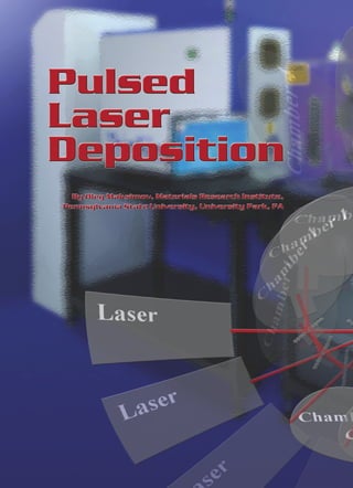
PLD, unlike many other deposition techniques, is based on the
very intuitive principles. A high-power pulsed laser is focused on
the target positioned in the vacuum chamber, as shown in
Figure 1. The target is ablated after each pulse forming a plume
Figure 1. The schematics of the PLD system. PLD chamber is equipped
with the substrate heater and a carousel housing a number of targets.
Laser beam is rastered over the target surface for better film uniformity.
59](https://image.slidesharecdn.com/pulsedlaserdeposition-130227114037-phpapp02/85/Pulsed-laser-deposition-2-320.jpg)
![highly energetic ions (100 eV-500 eV) and low energetic atoms
(10–50 eV). The high-energy fraction expands much faster reach-
ing the substrate first. When the high-energy ions hit the substrate,
they transfer kinetic energy activating diffusion of the surface
atoms, implanting atoms into the substrate, and re-sputtering
substrate atoms, as shown in Figure 5a. Next, re-sputtered
substrate atoms collide with the stream of slower-expanding
target atoms with lower kinetic energy. A high-temperature colli-
sion region characterized by high plasma and particle density
forms above the substrate, as shown in Figure 5b. Processes of
thermalization, condensation, and cluster formation start in this
region diminishing plasma density and finally dissolving the layer.
Finally, target atoms with the lowest kinetic energy (∼ 10 eV)
reach the substrate without interaction with the re-sputtered
substrate atoms, as shown in Figure 5c.
Therefore, film nucleation occurs under the heavy supersatu-
ration and the growth conditions are fare from the thermodynamic
equilibrium. The process can be separated into three steps:
a) High-energy ion implantation, surface diffusion activation,
and re-sputtering;
b) Cluster condensation from the collision zone;
c) Adsorption of the low-energy ablated species.
These steps are repeated after each laser pulse. While the high
degree of supersaturation favors two-dimensional (2D) nucleation
of highly dense and small clusters, high kinetic energy of arriving
species activates surface migration promoting layer-by-layer film
Figure 5. The schematic diagram of the plasma plume-substrate growth. Thus, films obtained by PLD are usually dense, exhibit
interaction high degree of texture, and demonstrate good adhesion proper-
Evaporating material forms a dense vapor layer above it. Laser ties. These properties are desirable both for the electronic materi-
beam interacts with the evaporated material dissociating molec- als and optical or tribological coatings.
ular species desorbed from the target. Photoionization (via the In spite of these advantages, a few shortcomings stalled broad
non-resonant multiphoton processes) causes plasma formation. industrial application of PLD. First, sub-surface boiling, expul-
Once formed, plasma attenuates laser beam by inelastic free elec- sion of the liquid layer by shock wave pressure recoil, and
tron scattering preventing further interaction between the laser exfoliation lead to the target splashing and particulate deposition.
beam and the target. These particulates vary in size from below hundred nanometers to
Due to the pressure differential, plasma expands from the tar- a few micrometers. They greatly affect growth of the subsequent
get surface forming the ''plasma plume". Internal thermal and ion- layers, degrade electrical properties of the films, and produce films
ization energies are converted into the kinetic energy reaching a with the rough surface. Second, plasma plume has a very narrow
few hundred electron volts (eV). The kinetic energy of the species angular distribution, which can be fitted by a cosnϕ curve (4 < n
and the spatial distribution of the plume strongly depend on the < 10 depending on the deposition pressure), resulting in the
chamber pressure. In general: non-uniform wafer coverage. Although this was not important for
academic research where 5×5 mm2 substrates were routinely used,
a) The plume is very narrow and forward directed at low pres- it made problematic industrial application where 4” wafer had to
sures (10-5 - 10-4 Torr). The kinetic energy of the species is be handled.
preserved since almost no scattering with the background gas However, these problems were mostly solved in the last years
occurs. by the joint efforts of a number of research groups.
b) Splitting of the high energy ions from the less energetic It was shown that particulates, which have much lower veloc-
species increases in the intermediate pressure range (1 - 10 ities than the atomic and ionic species, can be removed from
mTorr). The kinetic energy of the high energy ions is partially the plume using a mechanical velocity filter [12]. More elaborate
attenuated by the multiple collisions with the background gas. techniques involving collisions between two plasma plumes
c) Diffusion-like expansion of the ablated material occurs at (cross-beam PLD) [13], magnetic field filtering [14], and
higher pressures (> 0.1 Torr). High energy ions loose energy positioning the substrate edge-on inside the plume (off-axis
through the multiple scattering processes. deposition) instead of being directly perpendicular to it (on-axis
deposition) [15] were also developed.
As was previously mentioned, plasma plume consists of both A few schemes were implicated to improve film uniformity.
Vacuum Technology & Coating • July 2008 www.vactechmag.com or www.vtcmag.com 61](https://image.slidesharecdn.com/pulsedlaserdeposition-130227114037-phpapp02/85/Pulsed-laser-deposition-4-320.jpg)
![Figure 6. Principle of the multi-beam pulsed laser deposition approach Figure 7. The schematics of the multi-beam PLD integrated with the
(insert) and deviation of the deposition rate of TiCxN1−x over the de- commercial MBE system [20].
posited area [17].
2. H. M. Smith and A. F. Turner, Appl. 0pt., 4 147 (1965).
Rastering of the laser beam over the rotating target, which was 3. D. Dijkkamp, T. Venkatesan, X. D. Wu, S. A. Shaheen, N. Jasrawi,Y.
performed using a programmable kinematic mount installed on H. Min-Lee, W. L. McLean and M. Croft, Appl. Phys. Lett., 51, 619
the last mirror of the optical train, allowed deposition of the films (1987).
with the uniform coverage over the large wafer areas [16]. Other 4. T. Venkatesan, K. S. Harshavardhan, M. Strikovski, J. Kim in “Thin
Films and Heterostructures for Oxide Electronics” edited by S. B.
approaches included tilting of the rotating target during the laser
Ogale, Springer, (2005).
ablation, off-axis deposition, and positioning of the target with
5. G. Leggieri, A. P. Caricato, M. Fernandez, M. Martino, P. Mengucci,
the center of the plasma plume being slightly offset from the cen- G. Barucca, Recent Research Developments in Applied Physics, 5,
ter of the rotating substrate. In addition, a multi-beam PLD tech- 339 (2002).
nique produced films with a very low thickness deviation (∼ 5%) 6. M. Frumar, B. Frumarova, P. Nemec, T. Wagner, J. Jedelsky, M.
over the 4” wafers. In this case, three laser beams were focused on Hrdlicka, J. Non-Crystalline Solids, 352, 544 (2006).
the same target and the improved uniformity was achieved by the 7. A. J. Francis and P. A. Salvador, J. Mat. Res., 22, 89 (2007).
optimized superposition of the generated plasma plumes, as 8. A. Keffous, K. Bourenane, M. Kechouane, N. Gabouze, T. Kerdja,
shown in Figure 6 [17, 18]. Vacuum, 81, 632 (2007).
Multilayered coatings were deposited on the 4” wafers using 9. T. Hara, T. Yoshitake, T. Fukugawa, L. Y. Zhu, M. Itakura, N.
multi-beam PLD combined with the standard MBE into a novel Kuwano, Y. Tomokiyo, K. Nagayama, Diamond and Related Mate-
rials, 13, 679 (2004).
hybrid beam deposition [19,20]. The growth system was equipped
10. M. Lippmaa, T. Koida, H. Minami, Z. W. Jin, M. Kawasaki, H.
both with the effusion cells and multi-target carousel, quarts crys-
Koinuma, Appl. Surf. Sci., 189, 205 (2002).
tal monitor for flux calibration, ellipsometer and Reflective High 11. H. Koinuma, M. Kawasaki, M. Yoshimoto, Mat. Res. Soc. Symp.
Energy Electron Diffraction (RHEED) for in-situ monitoring, as Proc., 474, 303 (1997).
shown in Figure 7. Highly p-type doped ZnO, which is extremely 12. T.Yoshitake, G. Shiraishia, K. Nagayama, Appl. Surf. Sci., 197, 379
difficult to produce with other techniques, was also grown using (2002).
this technique [21]. While the ceramic target was used as a ZnO 13. A. Tselev, A. Gorbunov, W. Pompe, Rev. Sci. Instrum., 72, 2665
source, effusion cell was used to deliver Arsenic (p-type dopant) (2001).
and RF-plasma source was used to efficiently increase the flux 14. R. Jordan, D. Cole, J. G. Lunney, Appl. Surf. Sci., 109, 403 (1997).
density of available reactive oxygen. Hybrid beam deposition, al- 15. Z. Trajanovic, L. Senapati, R.P. Sharma, T. Venkatesan, Appl. Phys.
though lacking the simplicity of standard PLD, provides a real al- Lett., 66, 2418 (1995).
16. S. Boughaba, M. Islam, J. P. McCaffrey, G. I. Sproule, M. J. Graham,
ternative to the conventional vacuum deposition techniques.
Thin Solid Films, 371, 119 (2000).
Clearly, PLD has very exciting prospects and offers number of
17. J. M. Lackner, W. Waldhauser, R. Ebner, B. Major, Surf. Coat. Tech-
advantages over traditional vacuum deposition techniques like nol., 188, 519 (2005).
chemical vapor deposition, sputtering and e-beam evaporation. 18. J. M. Lackner, Thin Solid Films, 494, 302 (2006)
Since the problems of particulate deposition and non-uniform 19. M. Panzner, R. Dietsch, Th. Holz, H. Mai, S. Vdlmar, Appl. Surf.
wafer coverage are mostly solved, broader industrial application Sci., 96, 643 (1996).
of PLD is expected 20. M. Panzner, R. Dietsch, Th. Holz, H. Mai, S. Vdlmar, B. Wehner,
Appl. Surf. Sci., 127, 451 (1997).
References 21. Y. R. Ryu, T. S. Lee, H. W. White, J. Crystal Growth, 261, 4, 502
(2004).
1. “Pulsed Laser Deposition of Thin Films” edited D. B. Chrisey and G.
K. Hubler, Wiley-Interscience (1994).
62 vtcmag@optonline.net July 2008 • Vacuum Technology & Coating](https://image.slidesharecdn.com/pulsedlaserdeposition-130227114037-phpapp02/85/Pulsed-laser-deposition-5-320.jpg)

Pulsed laser deposition is a thin film growth technique where a high-power pulsed laser is focused on a target in a vacuum chamber, vaporizing the target material which then condenses on a substrate. It allows for the growth of a wide variety of oxide, nitride, metal and other films. The composition of the deposited film mimics that of the target. PLD systems are relatively inexpensive and easy to use, leading to its popularity in academic research. Key advantages include nearly stoichiometric transfer, flexibility in depositing different materials, and real-time thickness control. The laser-target interaction process involves rapid heating, vaporization and formation of an energetic plume that interacts strongly with the substrate during deposition.


![Thin_Film_Technology_introduction[1]](https://cdn.slidesharecdn.com/ss_thumbnails/1b4496c8-2102-411b-8465-a3dd3f398327-150205034538-conversion-gate02-thumbnail.jpg?width=640&height=640&fit=bounds)


