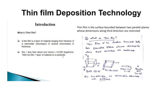
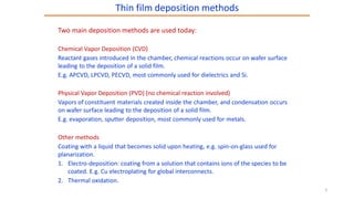
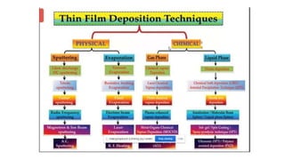
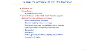
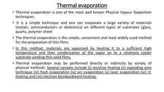
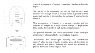
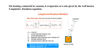
Thin film Deposition Technology
Thin film is the surface bounded between two parallel planes
whose dimensions along third direction are restricted
Two main deposition methods are used today:
Chemical Vapor Deposition (CVD)
Reactant gases introduced in the chamber, chemical reactions occur on wafer surface
leading to the deposition of a solid film.
E.g. APCVD, LPCVD, PECVD, most commonly used for dielectrics and Si.
Physical Vapor Deposition (PVD) (no chemical reaction involved)
Vapors of constituent materials created inside the chamber, and condensation occurs
on wafer surface leading to the deposition of a solid film.
E.g. evaporation, sputter deposition, most commonly used for metals.
Other methods
Coating with a liquid that becomes solid upon heating, e.g. spin-on-glass used for
planarization.
1. Electro-deposition: coating from a solution that contains ions of the species to be
coated. E.g. Cu electroplating for global interconnects.
2. Thermal oxidation.
Thin film deposition methods
3
• Deposition rate
• Film uniformity:
• Across wafer uniformity.
• Materials that can be deposited: metal, dielectric, polymer.
• Quality of film: Characterization techniques:
• Physical and chemical properties
• Electrical property, breakdown voltage
• Mechanical properties, stress and adhesion to substrate
• Optical properties, transparency, refractive index
• Composition
• Film density,
• Texture, grain size, boundary property, and orientation
• Impurity level, doping
General characteristics of thin film deposition
5
Thermal evaporation
• Thermal evaporation is one of the most well known Physical Vapour Deposition
techniques.
• It is a simple technique and one can evaporate a large variety of materials
(metals, semiconductors or dielectrics) on different types of substrates (glass,
quartz, polymer sheet
• The thermal evaporation is the simple, convenient and most widely used method
for the preparation of thin films.
• In this method, materials are vaporized by heating it to a sufficient high
temperature and then condensation of the vapor on to a relatively cooler
substrate yielding thin solid films.
• Thermal evaporation may be performed directly or indirectly by variety of
physical methods. Several variants include (i) resistive heating (ii) exploding wire
technique (iii) flash evaporation (iv) arc evaporation (v) laser evaporation (vi) r.f.
heating and (vii) electron bombardment heating.
A simple arrangement of thermal evaporation chamber is shown in
Figure.
The martial to be evaporated lies on the high inciting point
metallic boat through which a heating current is passed and the
evaporated material is deposited on the substrate S attached to the
heater H.
This arrangement is located in a vacuum chamber and the
chamber is pumped to a high vacuum through V. High-purity
films can be deposited from high-purity source material.
The possible problems that can be encountered in this technique
are the source of material to be vaporized and its purity.
Additionally, the line-of-sight trajectory and "limited-area
sources" allow the use of masks to define areas of deposition on
the substrate and shutters between the source and substrate to
prevent deposition on non-targeted areas.
On heating a material in vacuum, it evaporates at a rate given by the well known
Langmuire- Knudsen equation.
The vapour atoms thus formed are transported through to get scattered by collision
with gas atoms.
At pressures about 10-5 Torr the mean free path between collisions become large enough so
that the vapour beam arrives at the substrate unscattered.
The advantage of evaporation technique is the amount of impurities included in the
growing layer will be minimized and straight-line propagation will occur from the
source to the substrate.
The pressure that is required in a vacuum system to obtain satisfactory results, in
terms of reduction of included impurities and the fabrication of sharply defined
patterns, is about l x 10-6 Torr
Glow Discharge Sputtering
A glow discharge is a plasma formed by the passage of electric current through a
low-pressure gas. It is created by applying a voltage between two metal electrodes
in a glass tube containing gas. When the voltage exceeds a certain value called the
striking voltage, the gas in the tube ionizes, becoming a plasma, and begins
conducting electricity, causing it to glow with a colored light.
The simplest type of glow discharge is a direct-current glow discharge. In its simplest
form, it consists of two electrodes in a cell held at low pressure (1–10 torr).
The cell is typically filled with argon. A potential of several hundred volts is applied
between the two electrodes.
A small population of atoms within the cell is initially ionized through random
processes (collisions between atoms or with alpha particles, for example).
The ions (which are positively charged) are driven towards the cathode by the electric
potential, and the electrons are driven towards the anode by the same potential.
The initial population of ions and electrons collides with other atoms, ionizing them.
The fluorescent light bulb type of an arrangement is an evacuated glass tube with
circular disk electrodes at either end, connected to a high voltage DC power supply.
Once a sustainable DC glow discharge is established, it has a striking appearance of
alternating light and dark spaces. The structure of a typical low pressure glow discharge
is shown in Figure.
The Aston Dark Space (A) is a thin region close to the cathode. The electrical field is strong in this region
accelerating the electron away from the cathode. The Aston dark space has a negative space charge, meaning that
electrons outnumber the positive ions in this region
The description of various structures starts at the cathode and proceeds toward the anode:
In the Cathodic Glow, (B) next to the Aston dark space, the electrons are energetic enough to excite the neutral atoms
during collisions. The cathodic glow sometimes masks the Aston dark space as it approaches the cathode very closely.
The axial length of the cathode glow depends on the carrier gas, the pressure and temperature.
The Cathode (Crooks, Hittorf) dark space (C) is a relatively dark region that has a strong electric field, a positive space
charge and a relatively high ion density. Its axial extension depends on the pressure and the applied voltage. In this region
the electrons are accelerated by the electric field. Positive ions are accelerated towards the cathode. They cause the
pulverization of the cathode material and the emission of secondary electrons. These electrons will be accelerated and cause
the creation of new ions through collision with neutrals.
The Negative Glow NG (D) is the brightest intensity of the entire discharge. It extends typically for about 2-3 mm away
from the sample. Electrons carry almost the entire current in the negative glow region. Electrons that have been
accelerated in the cathode region to high speeds produce ionization. The NG is the region where most exciting and
ionizing collision processes occur because of the high density for both negative and positive charged particles in this area.
The Faraday dark space (E) separates the negative glow from the positive column. The electron
energy is low in this region. The net space charge is very low, and the axial electric field is small.
The Positive Column (F) is a luminous region that prolongs the negative glow to the anode. It
has a low net charge density, only a small electric field of typically 1 V/cm. The electric field is
just large enough to maintain the degree of ionization to reach the anode. As the length of the
discharge tube is increased at constant pressure, the cathode structures do not change in size. It is
the positive column that lengthens to form a long, uniform glow region.
The Anodic glow (G)is slightly brighter than the positive column. It is not always observed. The
anode glow is the boundary of the anode sheath.
The Anode dark space (H) or anode sheath is the space between the anode glow and the anode
itself. It has a negative space net charge density due to electrons traveling towards the anode. The
electric field is higher than in the positive column.
V-I (or) Ionization characteristics:
Electrodeposition technique is a process of coating a thin layer of one metal on top of a different metal to modify its
surface properties, by donating electrons to the ions in a solution.
This bottom-up fabrication technique is versatile and can be applied to a wide range of potential applications.
Electrodeposition is gaining popularity in recent years due to its capability in fabricating one-dimensional nano
structures such as nano rods, nano wires and nano tubes.
Electrodeposition is an electrochemical process that allows the preparation of solid deposits on the surface of
conductive materials. It is a commercially highly relevant process, providing the basis for many industrial
applications. such as metal plating. Metal plating is the process that has perhaps the closest contact with most
people’s everyday life, because we are surrounded by things that have a protective or decorative coating, such as
watches, buttons, belt buckles, doorknobs, handlebars, etc. Additionally and more recently, as will be seen below, not
only do the circuit boards and the packaging modules of computers,
but also the recording and reading heads of their hard disk drives and the microprocessor chip itself may have plated
material on them.
.
ELECTRODEPOSITION PROCESS
Electrodeposition is a process using electrical current to reduce cations of a desired material from a solution and coat
that material as a thin film onto a conductive substrate surface. Figure shows a simple electroplating system for the
deposition of copper from copper sulphate solution
Figure 1. Electrolytic cell for the deposition of copper from copper sulphate solution
The electrolytic solution contains positively charged copper ions (cations) and negatively charged sulphate ions (anions).
Under the applied external electric field, the cations migrate to the cathode where they are discharged and deposited as
metallic copper.
INFLUENCING FACTORS IN ELECTRODEPOSITION:
Conditions have to be provided so that the deposit will be fine grained and will have a smooth appearance. The
factors which affect the electro-deposition of metals are:
(i) Current Density
(ii) Electrolyte concentration
(iii) Temperature
(iv) Addition agents
(v) Nature of electrolyte
(vi) Nature of the metal on which the deposit is to be made
ADDITIONAL NOTES FOR ELECTRODEPOSITION METHOD FROM TEXT BOOKS

Thin film characterization techniques and tricks

  • 1.
    Thin film DepositionTechnology Thin film is the surface bounded between two parallel planes whose dimensions along third direction are restricted
  • 3.
    Two main depositionmethods are used today: Chemical Vapor Deposition (CVD) Reactant gases introduced in the chamber, chemical reactions occur on wafer surface leading to the deposition of a solid film. E.g. APCVD, LPCVD, PECVD, most commonly used for dielectrics and Si. Physical Vapor Deposition (PVD) (no chemical reaction involved) Vapors of constituent materials created inside the chamber, and condensation occurs on wafer surface leading to the deposition of a solid film. E.g. evaporation, sputter deposition, most commonly used for metals. Other methods Coating with a liquid that becomes solid upon heating, e.g. spin-on-glass used for planarization. 1. Electro-deposition: coating from a solution that contains ions of the species to be coated. E.g. Cu electroplating for global interconnects. 2. Thermal oxidation. Thin film deposition methods 3
  • 5.
    • Deposition rate •Film uniformity: • Across wafer uniformity. • Materials that can be deposited: metal, dielectric, polymer. • Quality of film: Characterization techniques: • Physical and chemical properties • Electrical property, breakdown voltage • Mechanical properties, stress and adhesion to substrate • Optical properties, transparency, refractive index • Composition • Film density, • Texture, grain size, boundary property, and orientation • Impurity level, doping General characteristics of thin film deposition 5
  • 6.
    Thermal evaporation • Thermalevaporation is one of the most well known Physical Vapour Deposition techniques. • It is a simple technique and one can evaporate a large variety of materials (metals, semiconductors or dielectrics) on different types of substrates (glass, quartz, polymer sheet • The thermal evaporation is the simple, convenient and most widely used method for the preparation of thin films. • In this method, materials are vaporized by heating it to a sufficient high temperature and then condensation of the vapor on to a relatively cooler substrate yielding thin solid films. • Thermal evaporation may be performed directly or indirectly by variety of physical methods. Several variants include (i) resistive heating (ii) exploding wire technique (iii) flash evaporation (iv) arc evaporation (v) laser evaporation (vi) r.f. heating and (vii) electron bombardment heating.
  • 7.
    A simple arrangementof thermal evaporation chamber is shown in Figure. The martial to be evaporated lies on the high inciting point metallic boat through which a heating current is passed and the evaporated material is deposited on the substrate S attached to the heater H. This arrangement is located in a vacuum chamber and the chamber is pumped to a high vacuum through V. High-purity films can be deposited from high-purity source material. The possible problems that can be encountered in this technique are the source of material to be vaporized and its purity. Additionally, the line-of-sight trajectory and "limited-area sources" allow the use of masks to define areas of deposition on the substrate and shutters between the source and substrate to prevent deposition on non-targeted areas.
  • 8.
    On heating amaterial in vacuum, it evaporates at a rate given by the well known Langmuire- Knudsen equation.
  • 9.
    The vapour atomsthus formed are transported through to get scattered by collision with gas atoms. At pressures about 10-5 Torr the mean free path between collisions become large enough so that the vapour beam arrives at the substrate unscattered. The advantage of evaporation technique is the amount of impurities included in the growing layer will be minimized and straight-line propagation will occur from the source to the substrate. The pressure that is required in a vacuum system to obtain satisfactory results, in terms of reduction of included impurities and the fabrication of sharply defined patterns, is about l x 10-6 Torr
  • 17.
    Glow Discharge Sputtering Aglow discharge is a plasma formed by the passage of electric current through a low-pressure gas. It is created by applying a voltage between two metal electrodes in a glass tube containing gas. When the voltage exceeds a certain value called the striking voltage, the gas in the tube ionizes, becoming a plasma, and begins conducting electricity, causing it to glow with a colored light.
  • 18.
    The simplest typeof glow discharge is a direct-current glow discharge. In its simplest form, it consists of two electrodes in a cell held at low pressure (1–10 torr). The cell is typically filled with argon. A potential of several hundred volts is applied between the two electrodes. A small population of atoms within the cell is initially ionized through random processes (collisions between atoms or with alpha particles, for example). The ions (which are positively charged) are driven towards the cathode by the electric potential, and the electrons are driven towards the anode by the same potential. The initial population of ions and electrons collides with other atoms, ionizing them. The fluorescent light bulb type of an arrangement is an evacuated glass tube with circular disk electrodes at either end, connected to a high voltage DC power supply. Once a sustainable DC glow discharge is established, it has a striking appearance of alternating light and dark spaces. The structure of a typical low pressure glow discharge is shown in Figure.
  • 19.
    The Aston DarkSpace (A) is a thin region close to the cathode. The electrical field is strong in this region accelerating the electron away from the cathode. The Aston dark space has a negative space charge, meaning that electrons outnumber the positive ions in this region The description of various structures starts at the cathode and proceeds toward the anode: In the Cathodic Glow, (B) next to the Aston dark space, the electrons are energetic enough to excite the neutral atoms during collisions. The cathodic glow sometimes masks the Aston dark space as it approaches the cathode very closely. The axial length of the cathode glow depends on the carrier gas, the pressure and temperature. The Cathode (Crooks, Hittorf) dark space (C) is a relatively dark region that has a strong electric field, a positive space charge and a relatively high ion density. Its axial extension depends on the pressure and the applied voltage. In this region the electrons are accelerated by the electric field. Positive ions are accelerated towards the cathode. They cause the pulverization of the cathode material and the emission of secondary electrons. These electrons will be accelerated and cause the creation of new ions through collision with neutrals. The Negative Glow NG (D) is the brightest intensity of the entire discharge. It extends typically for about 2-3 mm away from the sample. Electrons carry almost the entire current in the negative glow region. Electrons that have been accelerated in the cathode region to high speeds produce ionization. The NG is the region where most exciting and ionizing collision processes occur because of the high density for both negative and positive charged particles in this area.
  • 20.
    The Faraday darkspace (E) separates the negative glow from the positive column. The electron energy is low in this region. The net space charge is very low, and the axial electric field is small. The Positive Column (F) is a luminous region that prolongs the negative glow to the anode. It has a low net charge density, only a small electric field of typically 1 V/cm. The electric field is just large enough to maintain the degree of ionization to reach the anode. As the length of the discharge tube is increased at constant pressure, the cathode structures do not change in size. It is the positive column that lengthens to form a long, uniform glow region. The Anodic glow (G)is slightly brighter than the positive column. It is not always observed. The anode glow is the boundary of the anode sheath. The Anode dark space (H) or anode sheath is the space between the anode glow and the anode itself. It has a negative space net charge density due to electrons traveling towards the anode. The electric field is higher than in the positive column.
  • 21.
    V-I (or) Ionizationcharacteristics:
  • 25.
    Electrodeposition technique isa process of coating a thin layer of one metal on top of a different metal to modify its surface properties, by donating electrons to the ions in a solution. This bottom-up fabrication technique is versatile and can be applied to a wide range of potential applications. Electrodeposition is gaining popularity in recent years due to its capability in fabricating one-dimensional nano structures such as nano rods, nano wires and nano tubes. Electrodeposition is an electrochemical process that allows the preparation of solid deposits on the surface of conductive materials. It is a commercially highly relevant process, providing the basis for many industrial applications. such as metal plating. Metal plating is the process that has perhaps the closest contact with most people’s everyday life, because we are surrounded by things that have a protective or decorative coating, such as watches, buttons, belt buckles, doorknobs, handlebars, etc. Additionally and more recently, as will be seen below, not only do the circuit boards and the packaging modules of computers, but also the recording and reading heads of their hard disk drives and the microprocessor chip itself may have plated material on them. .
  • 26.
    ELECTRODEPOSITION PROCESS Electrodeposition isa process using electrical current to reduce cations of a desired material from a solution and coat that material as a thin film onto a conductive substrate surface. Figure shows a simple electroplating system for the deposition of copper from copper sulphate solution Figure 1. Electrolytic cell for the deposition of copper from copper sulphate solution The electrolytic solution contains positively charged copper ions (cations) and negatively charged sulphate ions (anions). Under the applied external electric field, the cations migrate to the cathode where they are discharged and deposited as metallic copper.
  • 27.
    INFLUENCING FACTORS INELECTRODEPOSITION: Conditions have to be provided so that the deposit will be fine grained and will have a smooth appearance. The factors which affect the electro-deposition of metals are: (i) Current Density (ii) Electrolyte concentration (iii) Temperature (iv) Addition agents (v) Nature of electrolyte (vi) Nature of the metal on which the deposit is to be made
  • 28.
    ADDITIONAL NOTES FORELECTRODEPOSITION METHOD FROM TEXT BOOKS