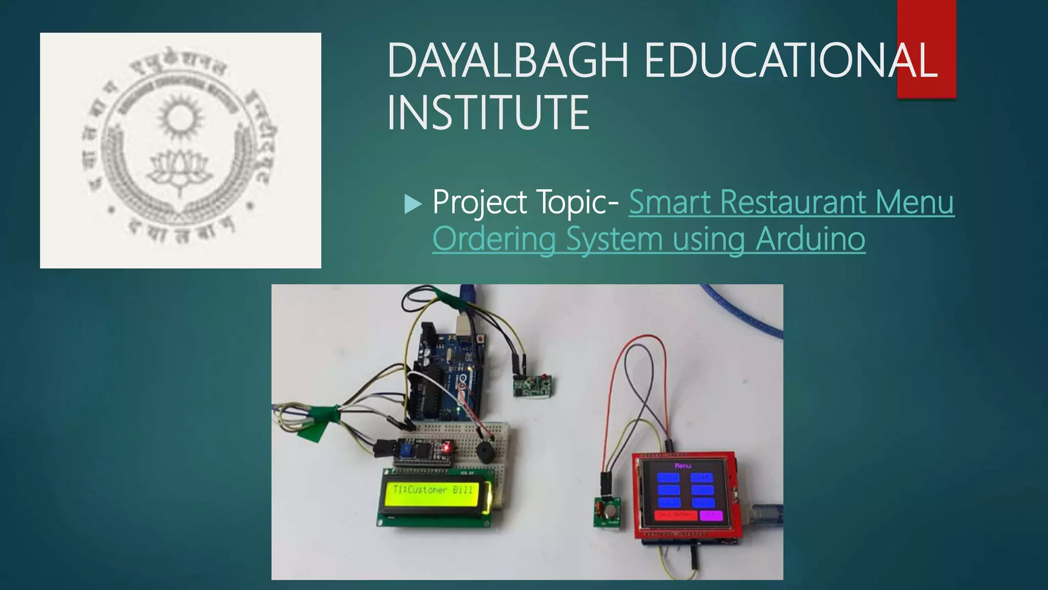
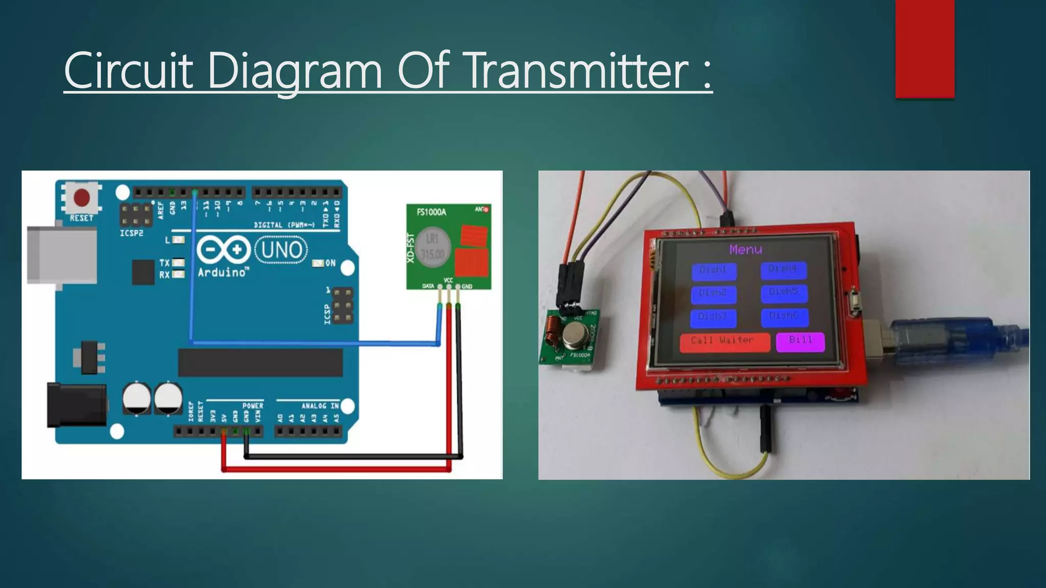
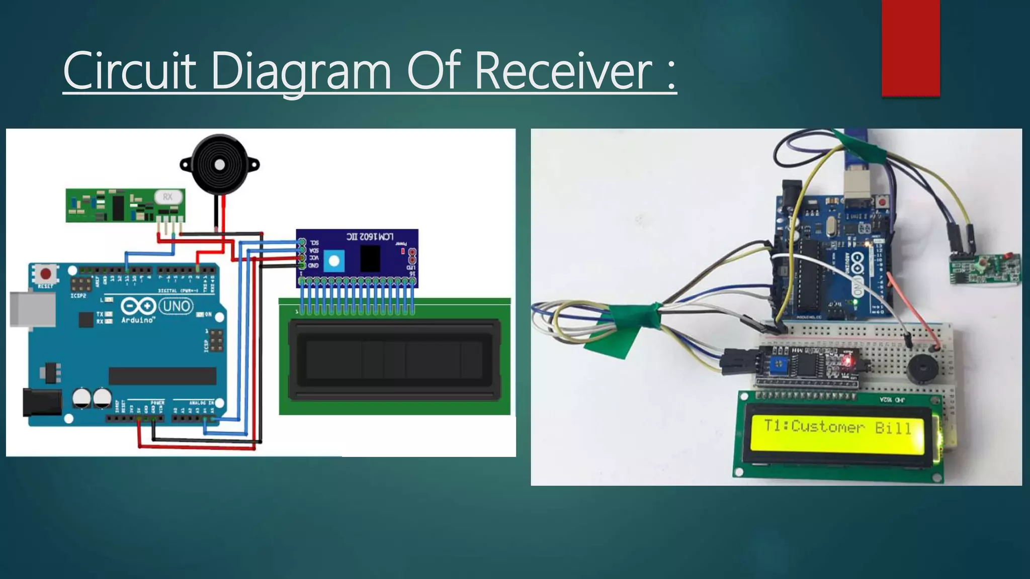
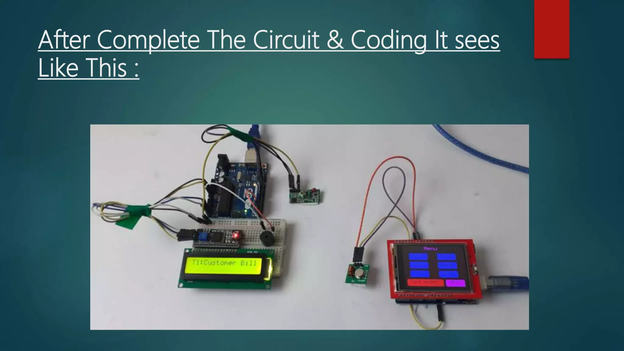
DAYALBAGH EDUCATIONAL
INSTITUTE
 Project Topic- Smart Restaurant Menu
Ordering System using Arduino
ITV-205
PROJECT
NAME –LALIT KUMAR
ROLL NO -1904801
CLASS-B.VOC(TELEMATICS)
Submitted To:
Mr. Hardik Sir
Submitted By:
Lalit Kumar
Topic-Smart Restaurant Menu
Ordering System using Arduino :
 Now day’s automation systems are everywhere
whether its home, office or any big industry, all are
equipped with automation systems.
Restaurants/Hotels are also adopting recent
automation trends and are installing robots to deliver
food and tablets for taking orders. Using these digital
menu cards like tablets, customers can easily select
the items. This information will be sent to the kitchen
of the Restaurant and also displayed on the display.
Components Required :
• Arduino Uno (2)
• 433MHz RF Transmitter & Receiver
• 2.4" TFT LCD Touch shield
• 16*2 LCD Module
• I2C Module
Photos Of Components :
About Circuit Diagram :
 Smart Restaurant Menu Ordering System
project consists of RF Transmitter and
Receiver section. Both the transmitter and receiver
side uses Arduino Uno for data processing. We
previously used the same 433 MHz RF modules with
Arduino for building projects like a wireless
doorbell, hand gesture controlled robot, etc.
Transmitter Section Circuit :
 The transmitter section of this project consists of an
Arduino Uno, RF Transmitter, and TFT display shield.
This section is used for ordering from the menu that
is shown on the TFT display. Arduino Uno is the
brain of the transmitter side that processes all the
data, and the RF transmitter module is used to
transmit the selected data to the receiver. The data
pin of the RF transmitter module is connected to
digital pin 12 of Arduino while VCC and GND pins are
connected to 5V and GND pin of Arduino.
Circuit Diagram Of Transmitter :
Receiver Section Circuit :
 The receiver section of this project consists of an Arduino Uno, RF
Receiver, 16*2 LCD module, and I2C module. RF receiver is used to
receive the data from the transmitter section, and the LCD module is used
to display the received data. A buzzer is used to make a sound whenever
a new order is placed. The data pin of the RF receiver is connected to
digital pin 11 of Arduino while VCC and GND pin is connected to the 5V
and GND pin of Arduino. The positive pin of Buzzer is connected to the
digital pin 2 of Arduino, and the negative pin is connected to the GND pin
of Arduino. SCL and SDA pins of the I2C module is connected to analog
pins A5 & A4 Arduino while VCC and GND pins are connected to 5V and
GND pins of Arduino.
Circuit Diagram Of Receiver :
Testing the Smart Restaurant Project using
Arduino :
 After connecting all the hardware and uploading the
code for both the transmitter and receiver section,
now it’s time to test the project. To test the project,
press a button on the TFT display, it should display
the dish name with table number that is T1 on the
LCD module connected to the receiver side. If the
receiver side LCD doesn’t display anything, then
check whether your TFT screen is working or not.
After Complete The Circuit & Coding It sees
Like This :
Thank You Sir.

Project(itv 205) smart restaurant menu ordering system using arduino

  • 1.
    DAYALBAGH EDUCATIONAL INSTITUTE  ProjectTopic- Smart Restaurant Menu Ordering System using Arduino
  • 2.
    ITV-205 PROJECT NAME –LALIT KUMAR ROLLNO -1904801 CLASS-B.VOC(TELEMATICS)
  • 3.
    Submitted To: Mr. HardikSir Submitted By: Lalit Kumar
  • 4.
    Topic-Smart Restaurant Menu OrderingSystem using Arduino :  Now day’s automation systems are everywhere whether its home, office or any big industry, all are equipped with automation systems. Restaurants/Hotels are also adopting recent automation trends and are installing robots to deliver food and tablets for taking orders. Using these digital menu cards like tablets, customers can easily select the items. This information will be sent to the kitchen of the Restaurant and also displayed on the display.
  • 5.
    Components Required : •Arduino Uno (2) • 433MHz RF Transmitter & Receiver • 2.4" TFT LCD Touch shield • 16*2 LCD Module • I2C Module
  • 6.
  • 7.
    About Circuit Diagram:  Smart Restaurant Menu Ordering System project consists of RF Transmitter and Receiver section. Both the transmitter and receiver side uses Arduino Uno for data processing. We previously used the same 433 MHz RF modules with Arduino for building projects like a wireless doorbell, hand gesture controlled robot, etc.
  • 8.
    Transmitter Section Circuit:  The transmitter section of this project consists of an Arduino Uno, RF Transmitter, and TFT display shield. This section is used for ordering from the menu that is shown on the TFT display. Arduino Uno is the brain of the transmitter side that processes all the data, and the RF transmitter module is used to transmit the selected data to the receiver. The data pin of the RF transmitter module is connected to digital pin 12 of Arduino while VCC and GND pins are connected to 5V and GND pin of Arduino.
  • 9.
    Circuit Diagram OfTransmitter :
  • 10.
    Receiver Section Circuit:  The receiver section of this project consists of an Arduino Uno, RF Receiver, 16*2 LCD module, and I2C module. RF receiver is used to receive the data from the transmitter section, and the LCD module is used to display the received data. A buzzer is used to make a sound whenever a new order is placed. The data pin of the RF receiver is connected to digital pin 11 of Arduino while VCC and GND pin is connected to the 5V and GND pin of Arduino. The positive pin of Buzzer is connected to the digital pin 2 of Arduino, and the negative pin is connected to the GND pin of Arduino. SCL and SDA pins of the I2C module is connected to analog pins A5 & A4 Arduino while VCC and GND pins are connected to 5V and GND pins of Arduino.
  • 11.
  • 12.
    Testing the SmartRestaurant Project using Arduino :  After connecting all the hardware and uploading the code for both the transmitter and receiver section, now it’s time to test the project. To test the project, press a button on the TFT display, it should display the dish name with table number that is T1 on the LCD module connected to the receiver side. If the receiver side LCD doesn’t display anything, then check whether your TFT screen is working or not.
  • 13.
    After Complete TheCircuit & Coding It sees Like This :
  • 14.