Download to read offline


![7| P a g e
CHAPTER 2
LITERATURE REVIEW
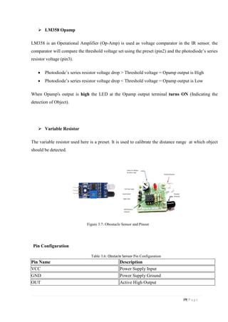
AUTONOMOUS ROBOT SYSTEM RESTAURNT [10]
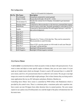
There are some basic requirements in creating an autonomous mobile robot: openness, abstraction
and modularity. These requirements are crucial so that a new function of robot can be constructed
from small changes of hardware and software design. Line following based on Infrared (IR)
photoelectric sensor is the basic knowledge to construct an autonomous mobile robot. It is an
intelligent system to ensure that the robot moves according to the line, in which if it moves out of
the line, the position corrective feedback will send data to the microcontroller. In order to perform a
good line following robot, the principle of IR sensor should be followed. The robot build has to
detect the line in the shortest time.
Thus, the IR sensor has to produce the best output so that the information can be sent to the
microcontroller, and gives faster reaction. In order to improve system reliability and accuracy, the
received reflected light will convert into output signal voltage, which directly affected by the
distance between the reflector and the sensor. There is a threshold voltage, where the distance of IR
sensor and reflector is optimum. The output received from IR sensor will pass through a comparator
in order to compare the voltage and send data to microcontroller. The sensor installation mode will
also affect the performance of sensor. Basically, the distance between the IR set sensor and the black
line should be more than 5mm. Also, the IR sensor will be fixed perpendicular to the reflector.
SMART RESTAURANT: SURVEY ON CUSTOMER DEMAND AND SALSE,
FORECASTING. [13]
Demand forecasting is one of the important inputs for a successful restaurant yield and revenue
management system. Sales forecasting is crucial for an independent restaurant and for restaurant
chains as well. In this chapter a comprehensive literature review and classification of restaurant sales
and consumer demand techniques are presented. Sales prediction is very complex due to the impact
of internal and external environment. However, a reliable sales forecasting methodology can
improve the quality of business strategy. A range of methodologies and models for forecasting are
given in the literature. These techniques are categorized here into seven categories, also including
hybrid models. The methodology for different kinds of analytical methods is briefly described, the](https://image.slidesharecdn.com/thesisbook-190905054804/85/Automated-Cafeteria-System-for-Efficient-Food-Serving-17-320.jpg)
![8| P a g e
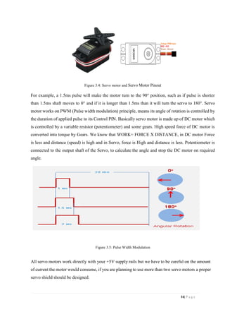
advantages and drawbacks are discussed, and relevant set of papers is selected. Conclusions and
comments are also made on future research directions.
AUTOMATION IN RESTAURANTS: ORDERING TO ROBOTS IN RESTAURANT
VIA SMART ORDERING SYSTEM [14]
Automation is everywhere; in one of our last paper we proposed a serving robot in restaurant to
automate the restaurants. In that paper we discussed some issues in existing serving robots in China
and Japan, and ordering to a robot is one from that issues. This paper is focusing on introducing
ordering system along with robotic waiter in restaurants in India. It is a web based application that a
customer can open on their smart phone. This system will help restaurants and hotels to increase
their star rating and reduce the human error at the time of taking orders. Already hotels are doing
new experiments to get notice by customers. For that they are registering in online applications also.
Our application is basically for the robotic restaurants to automate them.
INTELLIGENT RESTAURANT SYSTEM SMARTMENU. [15]
Digital technology is transforming business in many sectors, including restaurant systems and
service processes. Customers may recognize the replacement of paper-based menus with digital ones
as a first step of this process. Intelligent restaurant systems are an interesting application area for
merging and extension of cognitive capabilities with both intra-cognitive and inter-cognitive
communication. An intelligent restaurant system Smart menu, developed by Centria and Delitaz
Ltd., is an example of innovation which is based on merging and extending of cognitive capabilities.
These kinds of systems may change the everyday life in restaurants in the future. The system covers
the whole order process of a restaurant including the applications of the customer, the waiter, the
kitchen and the cashier. The first pilot systems were recently tested in several restaurants in Finland.
Piloting included also questionnaires and interviews analyzed by usability experts. In the future,
Smart menu may be extended to include also service robots in the system. The first demonstrations
of using service robot in a restaurant environment were already carried out.
DIGITAL ORDERING SYSTEM FOR RESTAURANT USING ANDROID. [10]
Nowadays web services technology is widely used to integrate heterogeneous systems and develop
new applications. Here an application of integration of hotel management systems by web services
technology is presented. Digital Hotel Management integrates lots of systems of hotel industry such](https://image.slidesharecdn.com/thesisbook-190905054804/85/Automated-Cafeteria-System-for-Efficient-Food-Serving-18-320.jpg)
![9| P a g e
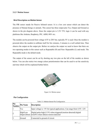
as Ordering System Kitchen Order Ticket (KOT), Billing System, Customer Relationship
Management system (CRM) together. This integration solution can add or expand hotel software
system in any size of hotel chains environment. This system increases quality and speed of service.
This system also increases attraction of place for large range of customers. Implementing this
system gives a cost-efficient opportunity to give your customers a personalized service experience
where they are in control choosing what they want, when they want it – from dining to ordering to
payment and feedback. We are implementing this system using android application for Tablet PC’s.
The front end will be developed using JAVA Android and the backend will work on MySQL
database.
SMART AUTOMATED RESTAURANT. [13]
Smart Automated Restaurant provides an efficient and user friendly system. This system will solve
key problems faced by restaurants today through the use of technologies such as Mobile and Web
applications, Android applications and cloud computing. Restaurants have much inefficiency due to
human limitations that can be resolved through automation. This Smart Automated Restaurant
accomplishes this by providing two interfaces for the two types of users in restaurants; an Android
mobile application for customers and a web application for restaurant staff members. The Android
mobile application allows customers to have a seamless dining experience with features such as
finding available parking spaces easier through Internet-connected infrared proximity sensors in the
parking lot. Also finding available tables at the restaurant gets easier through the use of sensors.
Ordering dishes through an interactive menu and being able to pay the bill from their Android
phones are some of the other features. The web application provides staff members benefits such as
collecting data and statistics on the restaurants performance in real time and automating the order
placement system for waiters and cooks.](https://image.slidesharecdn.com/thesisbook-190905054804/85/Automated-Cafeteria-System-for-Efficient-Food-Serving-19-320.jpg)
![29| P a g e
REFERENCES
Jun Zheng and Abbas Jamalipour, “Introduction to Wireless Sensor Networks”, Book: Wireless
Sensor Networks: A Networking Perspective, Wiley-IEEE Press, 2009.
Vijay Garg “Wireless Communication and Networking” 1st
Edition Imprint:Morgan Kaufmann
Print Book ISBN :9780123735805
Thirumurugan J, Kartheeswaran G, Vinoth M, Vishwanathan M. Line Following Robot for Library
Inventory Management System;2015. Coimbatore, India: Sri Ramakrishna Institute of Technology.
IEEE. p. 1-3.
Juhana Jauhiainen ,Sakari Pieska, , Antti Auno , Markus Liuska , Antti Auno Intelligent Restaurant
System Smart- menu CogInfoCom 2013, 4th
IEEE Conference on Cognitive Info communications,
December , 2013 , Budapest, Hungary.
Bajestani SEM & Vosoughinia A. Technical Report of Building a Line Follower Robot. 2015
International Conference on Electronics and Information Engineering (ICEIE 2010); 2015. p. V1-1
– V1-5.
Website: www.businessinsider.com, June-July 2019
A book named “Robot Restaurant Redux” written by Hunter.S.Thompson.
A book named “Robotics:A Refence guide to the new technology” written by Joseph A.Angelo Jr.
Ashutosh Bhargave, Niranjan Jadhav, Apurva Joshi, Prachi Oke, Prof. Mr. S. R Lahane,Department
of Computer Engineering, GES’s RHSCOE, International Journal of Scientific and Research
Publications, Volume 3, Issue 4, April 2013
Website: www.ijareeie.com Vol. 6, Issue 3, June-July 2019
Arduino Pro Mini pinout datasheet [Online] Available:
https://www.engineersgarage.com/electronic-components/arduino-pro-mini-pinout/
LCD working principal, Image, Pinout [Online] Available: https://www.elprocus.com/ever-
wondered-lcdworks/
Dhanashree Mirgal1, Pranjali Parab2, Amey Puro3, Bhawana Dakhare4, B.E Student1, 2, 3,
Assistant Professor4, Department of Information Technology, Bharati Vidyapeeth College of
Engineering, Mumbai, India.2018
A.Lasek,N.Cercone,J.Saunders Department of Electrical Engineering and Computer Science,
Lassonde School of Engineering, York University, Toronto, ON, Canada Fuseforward Solutions
Group, Vancouver, BC, Canada Available online 17 June 2016
International Journal of Converging Technologies & Management, Volume 4, Issue 1, 2018
1Neelima Mishra,2Dinesh Goyal,3Ashish Dutt Sharma
Juhana Jauhiainen at Centria University of Applied Sciences, Cognitive Infocommunications
(CogInfoCom), 2013 IEEE 4th International Conference on Cite this publication Sakari Pieskä at
Centria University of Applied Sciences, Ylivieska, Finland](https://image.slidesharecdn.com/thesisbook-190905054804/85/Automated-Cafeteria-System-for-Efficient-Food-Serving-39-320.jpg)
![30| P a g e
APPENDIX
INSTRUCTION CODE FOR PROGECT
sbit LCD_RS at RB3_bit;
sbit LCD_EN at RB2_bit;
sbit LCD_D4 at RB4_bit;
sbit LCD_D5 at RB5_bit;
sbit LCD_D6 at RB6_bit;
sbit LCD_D7 at RB7_bit;
sbit LCD_RS_Direction at TRISB3_bit;
sbit LCD_EN_Direction at TRISB2_bit;
sbit LCD_D4_Direction at TRISB4_bit;
sbit LCD_D5_Direction at TRISB5_bit;
sbit LCD_D6_Direction at TRISB6_bit;
sbit LCD_D7_Direction at TRISB7_bit;
#define servo RE0_bit
#define motorA RE1_bit
#define motorB RE2_bit
#define butt1 RD0_bit
#define butt2 RD1_bit
#define butt3 RD2_bit
#define butt4 RD3_bit
#define irSensor1 RD4_bit
#define irSensor2 RD5_bit
#define irSensor3 RD6_bit
#define irSensor4 RD7_bit
short checkpoint = 0;
const char txt1[] = "Welcome to Automated";
const char txt2[] = "Smart Cafeteria";
const char txt3[] = "Order Accepted";
const char txt4[] = "Wait for order";
const char txt5[] = "For return waste";
const char txt6[] = "press the button";
const char txt7[] = "For wait for";
const char txt8[] = "next order";
char txt[17];
void select_lcd(short n){
if(n == 1){
TRISB0_bit = 1;
TRISB1_bit = 0;
delay_ms(1);
lcd_init();
Lcd_Cmd(_LCD_CURSOR_OFF);](https://image.slidesharecdn.com/thesisbook-190905054804/85/Automated-Cafeteria-System-for-Efficient-Food-Serving-40-320.jpg)


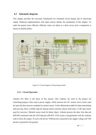
The document presents a project on an automated cafeteria system designed to enhance food ordering and serving efficiency using technology. It outlines the system's components, including a mobile app, LCD displays, and a conveyor belt for serving food, aimed at minimizing human error and improving customer satisfaction. The project, supervised by Mr. Md. Siddat Bin Nesar at Port City International University, discusses objectives, methodologies, and implications for future work in restaurant automation.


![Automatic power factor_improvement_and_monitoring_by_using_plc[1]](https://cdn.slidesharecdn.com/ss_thumbnails/automaticpowerfactorimprovementandmonitoringbyusingplc1-190905054934-thumbnail.jpg?width=640&height=640&fit=bounds)


