Download to read offline
![International Journal of Computer Science & Information Technology (IJCSIT) Vol 11, No 1, February 2019
62
2. LITERATURE REVIEW
2.1 E-TABLE: THE UNIQUE RESTAURANT INTERACTIVE ORDERING SYSTEM [1]
An ARM cortex-M3 is used for driving the Graphically Liquid Crystal Display (GLCD)screen
which is used for displaying the menu. The order will be sent using ZIGBEE module along with
the table number. A buzzer is then set to high in the kitchen's area. This system provides speech
recognition method as an input as shown in fig.1.
Figure 1. The E-Table's block diagram
2.2 WIRELESS TWO-WAY RESTAURANT ORDERING SYSTEM VIA TOUCH SCREEN
(WTROSTS) [2]
This system prioritizes the customers by "first come, first serve" and only one customer can
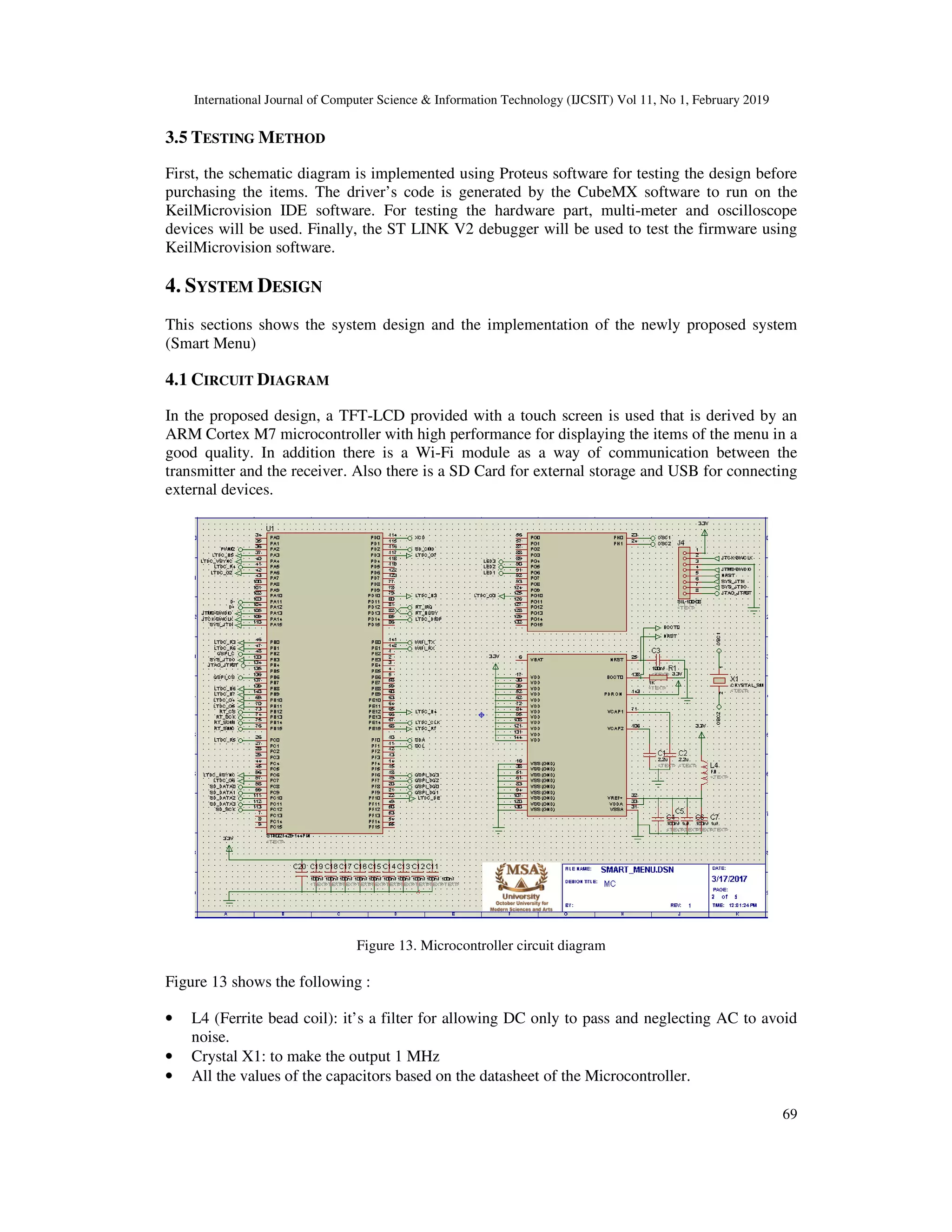
connect to the server at a time. The cooking room has a push button for sending back an
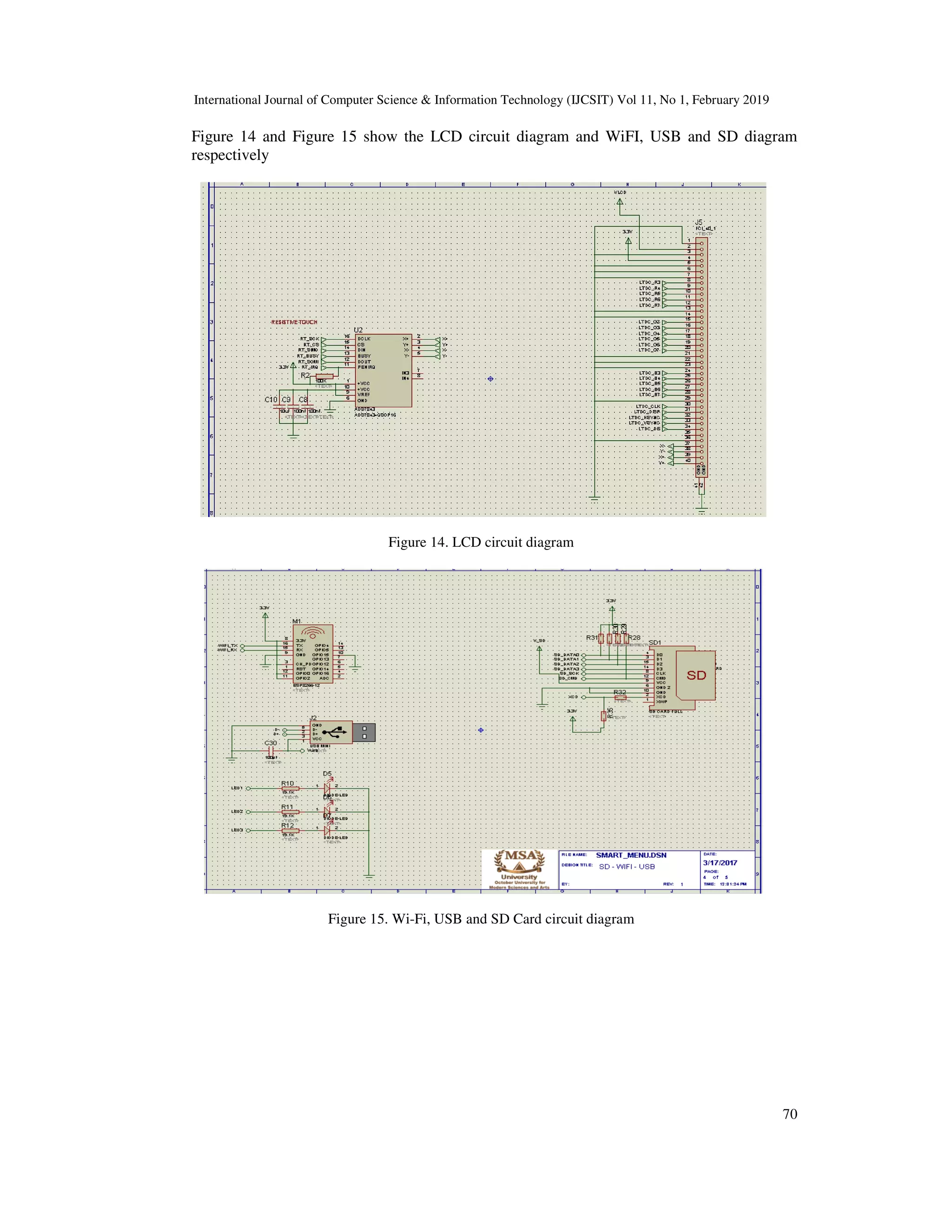
acknowledgment to the customer's table as an indication for placing the order as shown in fig 2
and fig 3.
Figure 2. The WTROSTS block diagram for the table](https://image.slidesharecdn.com/11119ijcsit05-190315112313/75/WI-FI-MICROCONTROLLER-BASED-SMART-MENU-2-2048.jpg)
![International Journal of Computer Science & Information Technology (IJCSIT) Vol 11, No 1, February 2019
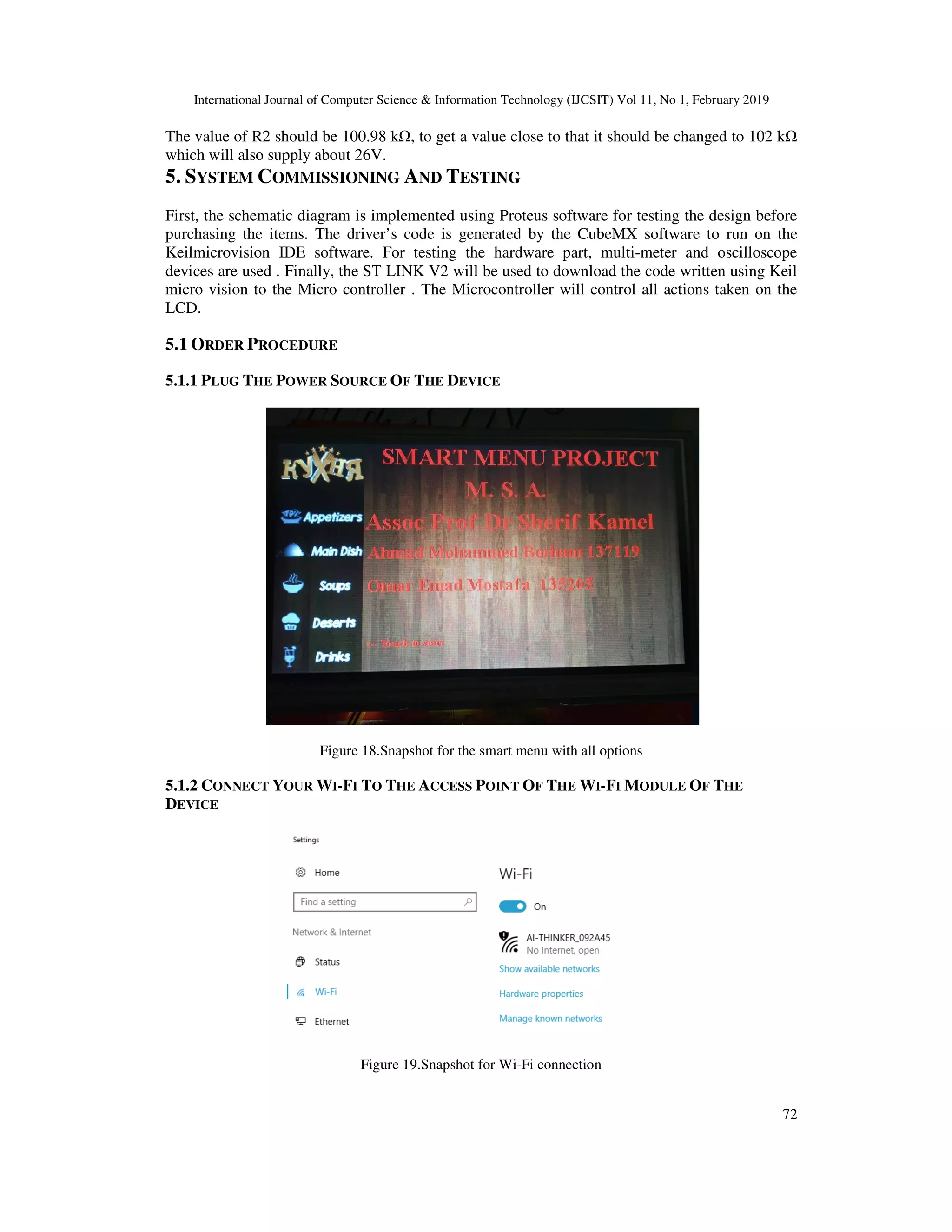
63
Figure 3. The WTROSTS block diagram for the kitchen
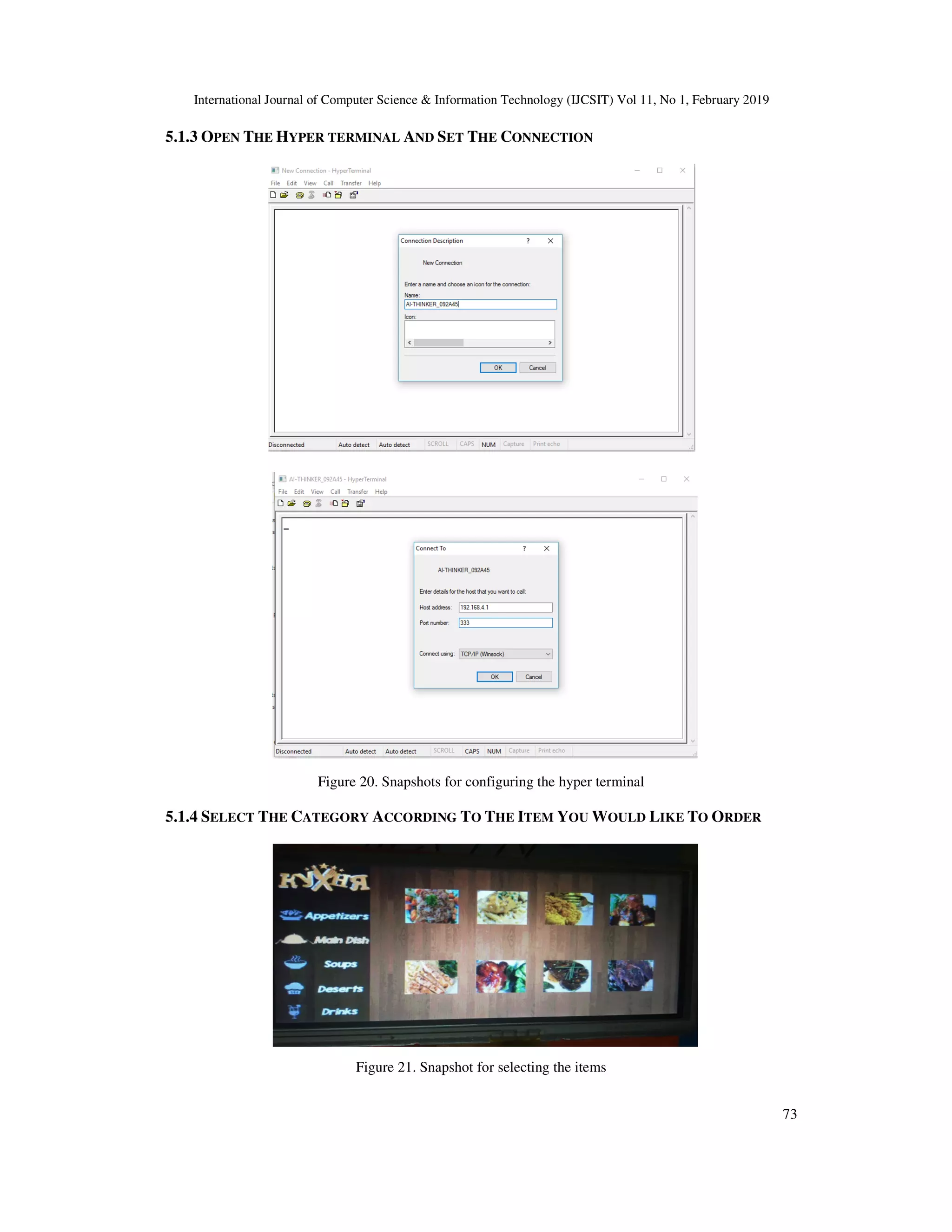
2.3 DESIGN AND DEVELOPMENT OF AN E-RESTAURANT USING RTOS PROGRAMMING
TO ENHANCE THE QUALITY OF SERVICE [3]
A touch screen graphical liquid crystal display (GLCD) acts as a menu recommender, the ARM
controller module is placed at the kitchen section and a PC with real time operating system
(RTOS) at the billing counter. The ZIGBEE technology is used for communication as shown in
fig 4.
Figure 4. ERRTOS frame work
2.4 DESIGN OF THE RESTAURANT SELF-ORDERING SYSTEM BASED ON ZIGBEE
TECHNOLOGY. (USING ARM CORTEX MICROCONTROLLER AND COLOR GLCD) [4]
This system includes two ARM microcontrollers one for the customer (transmitter) for making
orders and the other for the kitchen (receiver) to receive the order showing the information of the
order and the number of table that requested the order using ZigBee as the way of communication
between the transmitter and receiver as shown in fig 5 and 6](https://image.slidesharecdn.com/11119ijcsit05-190315112313/75/WI-FI-MICROCONTROLLER-BASED-SMART-MENU-3-2048.jpg)
![International Journal of Computer Science & Information Technology (IJCSIT) Vol 11, No 1, February 2019
64
Figure 5. Block diagram of RSOS's transmitter
Figure 6. Block diagram of RSOS's receiver
2.5 TOUCH SCREEN BASED ADVANCED MENU DISPLAY AND ORDERING SYSTEM FOR
RESTAURANTS [5]
The aim from this system from the cost wise aspect is to save spending a lot of money for similar
systems especially for restaurants that work on a small scale. A Graphically Liquid Crystal
Display (GLCD) provided with a touch screen that will display the menu items of the restaurant
and it connects with the receiver that contains Liquid Crystal Display (LCD) screen using RF
module as shown in fig 7 and fig 8.
Figure 7. AMDOS transmitter block diagram](https://image.slidesharecdn.com/11119ijcsit05-190315112313/75/WI-FI-MICROCONTROLLER-BASED-SMART-MENU-4-2048.jpg)
![International Journal of Computer Science & Information Technology (IJCSIT) Vol 11, No 1, February 2019
65
Figure 8. AMDOS receiver block diagram
2.6 SMART ORDERING SYSTEM VIA BLUETOOTH [6]
In this system the customer will make the order using keypad that will be placed on the table.
There will be a code with menu where the customer has to type the code to order the item he / she
wants and this code will be decrypted by the microcontroller. The order will be transmitted to the
computer in the kitchen through Bluetooth for preparing the order and to the counter computer for
the billing procedure as shown in fig 9
Figure 9. Block diagram of the Smart Ordering System
2. COMPARISON BETWEEN THE PROPOSED AND THE EXISTING SYSTEMS
Table 1 shows the features of the proposed system (Smart Menu) compared to the existing
systems.
Table 1. Performance comparison
Project Name
Calling
waiter
Feedback/
Rating
Order
status
Priority
Table
Number
Video
Display
Voice
Recognition
E-TABLE: ✗ ✗ ✗ ✗ ✗ ✗ ✓
WTROSTS ✓ ✗ ✓ ✓ ✗ ✗ ✓
ERRTOS ✗ ✗ ✓ ✗ ✗ ✗ ✗
RSOS ✗ ✗ ✓ ✗ ✓ ✗ ✗
AMDOS ✗ ✓ ✓ ✗ ✓ ✗ ✓
Smart Ordering
System
✗ ✗ ✗ ✗ ✓ ✗ ✗
Smart Menu ✓ ✓ ✓ ✓ ✓ ✓ ✓](https://image.slidesharecdn.com/11119ijcsit05-190315112313/75/WI-FI-MICROCONTROLLER-BASED-SMART-MENU-5-2048.jpg)
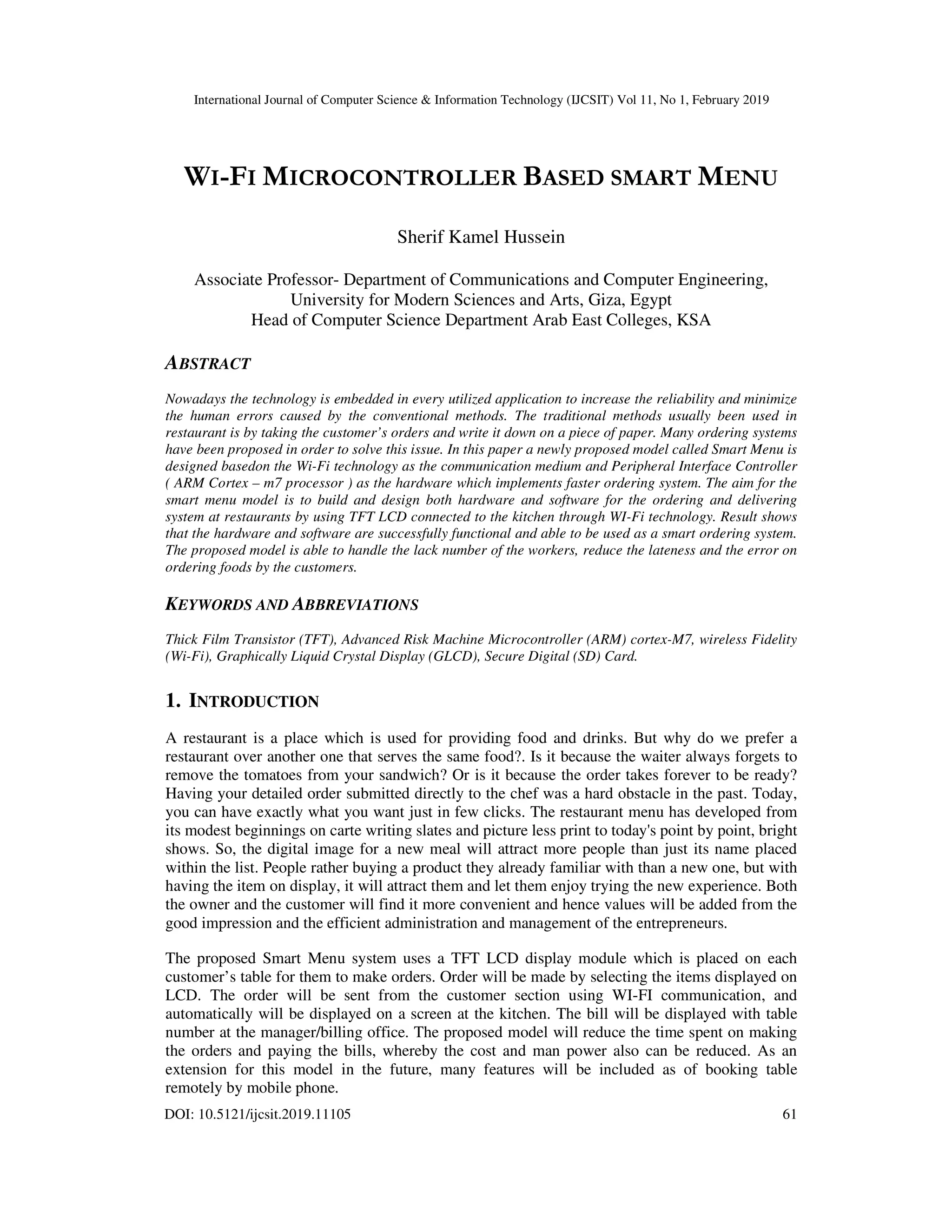
![International Journal of Computer Science & Information Technology (IJCSIT) Vol 11, No 1, February 2019
67
"controller" part is because they are used to control gadgets, machines and else. They are
designed for controlling machine applications, rather than a human interaction [7].
Microcontrollers are divided into categories according to their architecture, memory, number of
bits and the instruction sets used. Many microcontrollers have completely different features.
ARM Cortex-M7 microcontroller will be used in The proposed system which has many features
as shown below:
• A 6-stage pipeline that can execute up to two instructions per a clock cycle.
• Instruction cache from 4KB to 64KB
• Data cache from 4KB to 64KB
• Optional ECC (Error Correction Code) support for the cache memories
• A 64-bit AXI system bus interface
• A 64-bit instruction tightly coupled memory (ITCM)
• An optional dual 32-bit Data Tightly-Coupled Memory (TCM) with Error-Correcting
Code(ECC) support for customer and implementing the TCM memory arrays.
• Low latency Advanced High-Performance (AHB) peripheral bus interface that allows fast
access and deterministic to peripherals in real-time applications.
The reason for choosing this type of the microprocessor because of its specifications and
objectives mentioned before. Besides that, this item was available to be ordered online with a
great price according to its features. The ARM Cortex-M3 was another competitive for having
similar features but the ARM Cortex-M7 is chosen to be used in the proposed Smart Menu Model
3.3.2 THE LCD
As innovation included, a touch screen LCD will probably pull in more clients. The touch screens
are classified into two types’ single touch and multi touch. The single touch is not prone to be
utilized these days for its absence of capacities while the multi touch screens have two types,
capacitive touch screens and resistive touch screens [8]
The capacitive touch panels are made of n insulator which consists of glass coated with a
transparent conductor which is made of indium tin oxide (ITO) and since the body of a human
acts a good conductor of electricity therefore when contact is occurred between the human body
and the Capacitive Touch Panel that will cause a distortion to electrostatic field of the touch
panel. The display will respond according to the reading of touch panel’s distortion.
The resistive touch panel is made up of many different layers. Pressing down onto the touch panel
with a finger or a stylus, the layer on the top flexes and then pushes the layer behind it. As a
result, a complete circuit will be created and then it notifies the controller which part of the touch
panel has been press on.
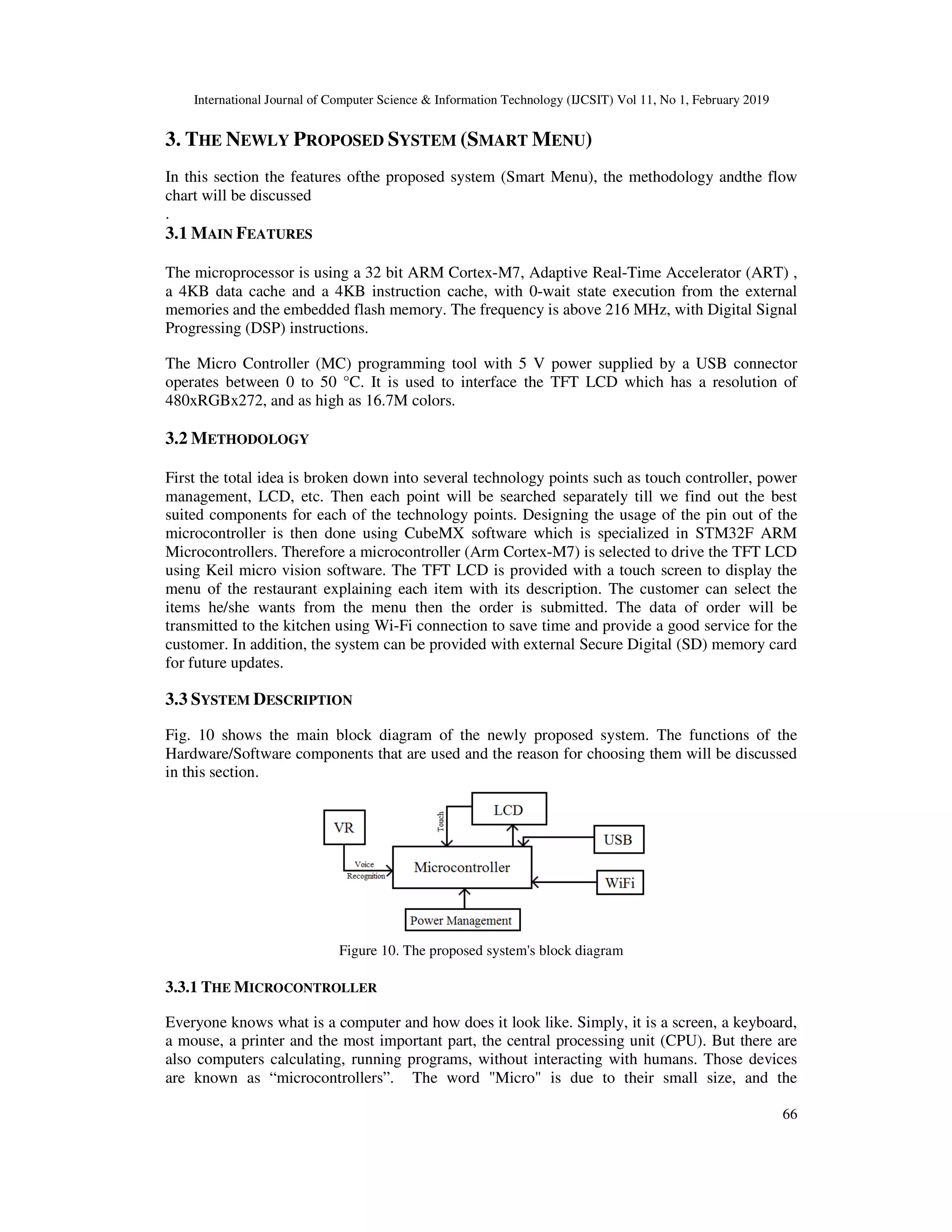
In the proposed system a TFT LCD will be used which is a resistive touch screen as seen in Fig
11. The most common TFT design is the inverse staggered structure. This structure presents high
electron mobility and many advantages of a simple fabrication process. The first step in the TFT
array fabrication consists of gate and storage-capacitor electrodes construction with 2000-3000 A
of a metal such as, chromium, aluminum, tungsten or tantalum layer deposition then a triple layer
of amorphous silicon and silicon nitride. It is then deposited using plasma-enhanced chemical
vapor deposition (PECVD).](https://image.slidesharecdn.com/11119ijcsit05-190315112313/75/WI-FI-MICROCONTROLLER-BASED-SMART-MENU-7-2048.jpg)


![International Journal of Computer Science & Information Techno
added too to the system. For example, adding a credit card payment to the system will make the
process easier for many customers. Also, adding
using the mobile phone will help the customers to reserve their table before arriving to the
restaurant.
REFERENCES
[1] V. Chandra Sekhara Santosh, A. Shanker“
International Journal of Engineering and Science, Vol.4, No.8, pp.644
[2] B.Vinodhini, K.Abinaya, R.Roja, M.Rajeshwari “Wireless Two
Touch Screen” The International Journal Of Engineering And Scienc
[3] B.Vinodhini, K.Abinaya, R.Roja, M.Rajeshwari,”
RTOS programming to Enhance the Quality of Service”, International Journal of Inventions in
Electronics & Electrical Engine
[4] Dr. ShaikMeeravali ,K.Sudhakar, M.Swathi “Design of the Restaurant Self
on ZigBee Technology. (Using ARM cortex microcontroller and color GLCD)” International Journal
of Engineering Research & Technology, Vol.2, No.9, pp.730
[5] Venmathi.V, Eswari.M, Jasmine Jenita.R, Jayasri.S, Kavitha.R “Touch Screen Based Advanced
Menu Display and Ordering System for Restaurants” International Journal of Engineering Science
and Computing, Vol.6, No.4, pp.3482
[6] N. M. Z.Hashim, N. A. Ali, A.S. Jaafar, N.R.Mohamad, L.Salahuddin, N. A. Ishak, “Smart Ordering
System via Bluetooth”, International Journal of Computer Trends and Technology,pp.2253
2256,2013.
[7] Gracia, D. and Yiu, J. (2015) Exploring the ARM® Cortex®
Internet of Tomorrow. Available at: http://www.nxp.com/assets/documents/data/en/white
papers/CORTEXM7WP.pdf
[8] Lagerstam, C. (2016) Newhaven display international, Inc., high
LCDs and VFDs. Available at: http://www.newhavendisplay.com/app_notes/TPcompare.pdf
AUTHOR
Sherif Kamel Hussein Hassan Ratib
1989 Communications and Electronics
Diploma, MSc, and Doctorate in Computer Science
Technology and Networking. He has been working in many private and governmental
universities inside and outside Egypt for almost 15 years.
of many industrial courses. His research interest is GSM Based Control and Macro
mobility based Mobile IP. He is an Associate Professor and Faculty Member at
Communications and Computer Engineering department in October Universit
Modern Sciences and Arts - Egypt. Now he is working as head of Computer Science
department in Arab East Colleges for Postgraduate Studies in Riyadh
International Journal of Computer Science & Information Technology (IJCSIT) Vol 11, No 1, February 2019
added too to the system. For example, adding a credit card payment to the system will make the
for many customers. Also, adding the possibility of booking the table remotely
help the customers to reserve their table before arriving to the
V. Chandra Sekhara Santosh, A. Shanker“ The Unique Restaurant Interactive Ordering System
International Journal of Engineering and Science, Vol.4, No.8, pp.644-650, Aug 2014.
B.Vinodhini, K.Abinaya, R.Roja, M.Rajeshwari “Wireless Two-way Restaurant Ordering System via
Touch Screen” The International Journal Of Engineering And Science, Vol.3, No.7, pp. 01
B.Vinodhini, K.Abinaya, R.Roja, M.Rajeshwari,” Design and Development of an E- Restaurant using
RTOS programming to Enhance the Quality of Service”, International Journal of Inventions in
Electronics & Electrical Engineering, Vol.1, pp. 1-9, Jan-Dec 2015.
Dr. ShaikMeeravali ,K.Sudhakar, M.Swathi “Design of the Restaurant Self-Ordering System Based
on ZigBee Technology. (Using ARM cortex microcontroller and color GLCD)” International Journal
Technology, Vol.2, No.9, pp.730-733, Sep 2013.
Venmathi.V, Eswari.M, Jasmine Jenita.R, Jayasri.S, Kavitha.R “Touch Screen Based Advanced
Menu Display and Ordering System for Restaurants” International Journal of Engineering Science
.6, No.4, pp.3482-3485, Apr 2016.
N. M. Z.Hashim, N. A. Ali, A.S. Jaafar, N.R.Mohamad, L.Salahuddin, N. A. Ishak, “Smart Ordering
System via Bluetooth”, International Journal of Computer Trends and Technology,pp.2253
, J. (2015) Exploring the ARM® Cortex®-M7 Core: Providing Adaptability for the
Internet of Tomorrow. Available at: http://www.nxp.com/assets/documents/data/en/white
Lagerstam, C. (2016) Newhaven display international, Inc., high quality standard and custom OLEDs,
LCDs and VFDs. Available at: http://www.newhavendisplay.com/app_notes/TPcompare.pdf
Sherif Kamel Hussein Hassan Ratib: Graduated from the faculty of engineering in
1989 Communications and Electronics Department, Helwan University. He received his
and Doctorate in Computer Science-2007, Major Information
Technology and Networking. He has been working in many private and governmental
universities inside and outside Egypt for almost 15 years. He shared in the development
of many industrial courses. His research interest is GSM Based Control and Macro
mobility based Mobile IP. He is an Associate Professor and Faculty Member at
Communications and Computer Engineering department in October University for
Egypt. Now he is working as head of Computer Science
department in Arab East Colleges for Postgraduate Studies in Riyadh- KSA.
logy (IJCSIT) Vol 11, No 1, February 2019
76
added too to the system. For example, adding a credit card payment to the system will make the
the possibility of booking the table remotely
help the customers to reserve their table before arriving to the
The Unique Restaurant Interactive Ordering System”, The
way Restaurant Ordering System via
e, Vol.3, No.7, pp. 01-05, 2014.
Restaurant using
RTOS programming to Enhance the Quality of Service”, International Journal of Inventions in
Ordering System Based
on ZigBee Technology. (Using ARM cortex microcontroller and color GLCD)” International Journal
Venmathi.V, Eswari.M, Jasmine Jenita.R, Jayasri.S, Kavitha.R “Touch Screen Based Advanced
Menu Display and Ordering System for Restaurants” International Journal of Engineering Science
N. M. Z.Hashim, N. A. Ali, A.S. Jaafar, N.R.Mohamad, L.Salahuddin, N. A. Ishak, “Smart Ordering
System via Bluetooth”, International Journal of Computer Trends and Technology,pp.2253-
M7 Core: Providing Adaptability for the
Internet of Tomorrow. Available at: http://www.nxp.com/assets/documents/data/en/white-
quality standard and custom OLEDs,
LCDs and VFDs. Available at: http://www.newhavendisplay.com/app_notes/TPcompare.pdf](https://image.slidesharecdn.com/11119ijcsit05-190315112313/75/WI-FI-MICROCONTROLLER-BASED-SMART-MENU-16-2048.jpg)

The document details the development of a Wi-Fi microcontroller-based smart menu system for restaurants, designed to enhance the ordering and billing process using a TFT LCD interface. The system aims to reduce human error, improve service efficiency, and allow customers to place orders more conveniently. It features an ARM Cortex M7 processor and uses Wi-Fi for communication between customer tables and the kitchen.