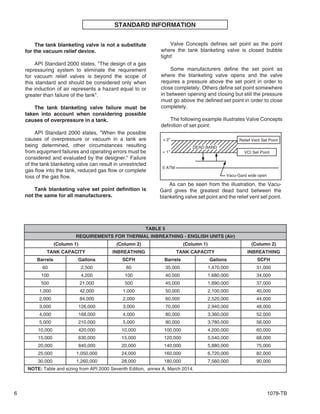
SlideShare a Scribd company logo
1 of 14
Download to read offline
TECHNICAL BULLETIN
Model 1078
Vacu-Gard®
Tank Blanketing Valve
1” & 2” (DN25 & DN50)
The Model 1078 is a pilot-operated valve, specifically
designed to reduce blanketing gas losses on low-
pressure storage tanks. It opens and closes automatically
as required, to maintain a closely controlled blanket
pressure. The simple design, increases reliability and
lowers maintenance cost.
1078 - TB
02-16
1" Model 1078
U.S. Pat. No. 4991620, 5067522 and 5094267
Valve Concepts, Inc.
Application
On many low-pressure storage tanks the operating
range is very low, which makes blanketing and venting
system selection/design a challenge for the engineer.
The Vacu-Gard®
makes the job much easier. First, the
Vacu-Gard®
set point definition is where the blanketing
valve closes bubble tight. This gives the largest dead
band between the blanketing valve set point and the set
point of the relieving device, and therefore will reduce
losses. Second, the Vacu-Gard®
has a wide range of
available settings, from vacuum to 14 psig, that make
proper selection easier.
Versatile:
Top entry
Design:
Stability:
Performance:
Shutoff:
Lower
Maintenance
Costs:
Single valve system offers wide
variety of configurations to meet
every blanketing application. Self
cleaning flow design.
Compact and light weight yet
allows complete access to the valve
internalswithoutbeingremovedfrom
the tank. Only time the diaphragm
case needs to be disassembled is
when replacing the diaphragm.
Pressurebalancedpilot. Fluctuations
insupplypressuredoesnotaffectset
point.
Valve set point can be verified
100% on the tank, without removal
and without flowing supply gas into
the tank. Temperature changes
have no appreciable effect on set
point
Bubble tight at set point, prevents
waste of blanketing gases.
Uses standard o-rings for seat and
seals.
FEATURES
ISO Registered Company
2 1078-TB
GENERAL SPECIFICATIONS
Sizes
1” (DN25) Body
2" (DN50) Body
Connections
1" & 2" FNPT (screwed)
1" 150# integral RF flanges'
1" 300# weldneck RF flange
2" 150# & 300# RF weldneck flanges
DN25 (PN40), DN50 (PN16) & DN50 (PN40)
weldneck flanges.
Special configurations are available on request:
Any combination of above.
Larger size reducing flanges .
Outlet Configurations
Horizontal or Vertical
Valves with FNPT connections can be configured
in the field. Valves with weldneck flange connec
tions, configuration must be specified at time of
order.
Sensing Options
Remote sensing
Integral dip tube sensing (Vertical Outlet Only)
Supply Pressures
Minimum: 20 psig (1.38 Bar)
Maximum: 200 psig (13.83 Bar)
Capacities
See Table 6
Outlet Pressure Ranges
See Table 3
Maximum Back Pressures
25 psig (1.7 Bar)
Materials of Construction
Diaphragm Case Material:
Carbon Steel (Powder Coated)
Stainless Steel
Hastelloy C®
Trim Material:
316 Stainless Steel
Hastelloy C®
Diaphragm Material:
PTFE
Soft Seat & Seals:
FKM is standard;
Buna-N, EPDM,
FFKM 1 - Similar to Chemraz
FFKM 2 - Similar to Kalrez
Temperature Limits
Seat & Seal Materials
FKM (Fluorocarbon Elastomer):
-15° to 300° F (-26° to 149° C)
Buna-N (Nitrile-NBR):
-40° F to 212° F (-40° C to 100° C)
EPDM (Ethylenepropylene):
-55° F to 212° F (-48° C to 100° C)
FFKM 1 (Perfluoroelastomer):
-22° F to 400° F (-30° C to 204° C)
FFKM 2 (Perfluoroelastomer):
-40° F to 400° F (-40° C to 204° C)
Hastelloy®
is a registered trade name:
Hastelloy®
is a mark owned by Stelite Div., Cabot Corp.
Pressure - Temperature Specifications
Body
Material
End
Connection
Inlet
Pressure
Temperature
F(C)*
Carbon
Steel **
NPT, 150# &
300#Flange
200 psig
(13.8 Barg)
-20 to 400
(-29 to 204)
Stainless
Steel
A352
CF3M
NPT & 300#
Flange
200 psig
(13.8 Barg)
-50 to 400
(-45 to 204)
150# Flange
200
(13.8 Barg)
-325 to 300
(-198 to 149)
195
(13.4 Barg)
-325 to 400
(-198 to 204)
Hastelloy
C ®
NPT, 150# &
300#Flange
200
(13.8 Barg)
-50 to 400
(-45 to 204)
* Design temperature limits maybe restricted by trim
selection
** Only available in 2" (DN50) Size.
Standard: Exterior coating will be a
combination of Cashco Paint Specs #S-
1777 epoxy and #S-1743 powder coated.
Tubing,fasteners,seatsurfaces-corrosion
resistant parts excluded.
Alternate Paint: See Opt-95OS.
Paint
1078-TB 3
CAPACITY REQUIREMENTS
The capacity requirement of the tank blanketing
valve is the sum of two components. The first being
inbreathing due to liquid or product movement out
of the tank and the second being inbreathing due to
contraction of the vapors/product because of weather
changes.
Inbreathing due to maximum liquid or product
movement out of the tank equals 8.0 SCFH of air for
each US gallon per minute of maximum emptying
rate or 0.94 Nm3
/h of air for each m3
/h of maximum
emptying rate.
Qdisplacement(SCFH)=Max.PumpoutRate(gpm)x8.0
or
Qdisplacement(Nm3
/h)=Max.PumpoutRate(m3
/h)x.94
The second component, inbreathing due to
weather changes, is selected from Table 5 (Table
5A). The tank capacity is found in column 1 and the
corresponding inbreathing requirement is selected
from column 2.
The two components are added together to give
the total inbreathing requirement and the capacity
requirement of the tank blanketing valve.
Q total = Q displacement + Q thermal
VALVE SELECTION
If the tank blanketing supply pressure varies, use
the minimum supply pressure in selecting the tank
blanketing valve and the maximum supply pressure
to determine blanketing valve failure capacity. Using
the minimum supply pressure, select the size value
from Table 6 that will meet the Total Inbreathing
Requirement (Q total). Next determine if a reducing
"flow plug" can be used to make the capacity of
the tank blanketing valve more closely match the
inbreathing requirements. This will also reduce the
fail open capacity of the blanketing valve. This is done
by dividing the required inbreathing (Q total) by the
full capacity of the size valve selected and multiplying
by 100. Now from Table 2, choose the flow plug that
is greater than the calculated percentage.
Example:
Total inbreathing requirement (Q total) = 25,850 SCFH
Maximum supply pressure = 100 psig
Minimum supply pressure = 80 psig
Next divide the total inbreathing requirement
of 25,850 SCFH by the 1" valve capacity of 35,990
SCFH (at 80 psig) and multiply by 100.
(25,850 SCFH / 35,990 SCFH) x 100 = 71.8%
From Table 2, a 75% flow plug would be chosen
for a 1" valve. With the 75% flow plug, the blanketing
valve will flow 26,993 SCFH at 80 psig and at the
maximum supply pressure of 100 psig it will flow
32,693 SCFH. The 32,693 SCFH also represents
the fail open flow of the blanketing valve and will
be used in sizing the pressure relieving device.
NORMAL INSTALLATION
1078-TB4
VALVE OPERATION
Figure 1 shows the Vacu-Gard®
in the closed
position. This occurs when the tank pressure
satisfies or exceeds the set pressure of the pilot.
When the sensed pressure is sufficient to overcome
the downward force of the set pressure spring, the
pilot will close and there is no flow out of the pilot.
This causes full supply pressure to accumulate in
the chamber above the main valve piston. Since the
piston area is larger than the seat area at the lower
end of the piston, when the pressure above the piston
is equal to the supply pressure the piston will move
downward to close the valve due to the presence of a
higher downward force.
Figure 2 shows the Vacu-Gard®
in the open
position. When the tank pressure, that is sensed
in the sense chamber below the diaphragm, is
insufficient to hold against the downward force of the
set pressure spring, the spindle in the pilot chamber
will be forced downward. As the spindle unseats, the
pressure in the pilot chamber will be discharged into
the outlet of the valve. A small orifice restricts the gas
flow into the pilot chamber from the supply pressure.
Therefore, as soon as the pilot spindle opens, the
pilot chamber pressure will drop significantly and will
not be able to hold the main valve piston down. The
piston will now be pushed full open by the supply
pressure, allowing a maximum flow of the blanketing
gas into the tank.
Once the tank pressure is back to set point, the
spindle will close and the pilot pressure will rise to full
supply pressure, pushing the main valve piston back
down into the fully closed position.
Open Position
Closed Position
Figure 1
Figure 2
1078-TB 5
TABLE 1
STANDARD MATERIALS OF CONSTRUCTION
SIZE
MAIN BODY
*
PILOT
BODY
DIAPHRAGM
CASES
SPRING
BONNET
TRIM
SENSE
DIAPH
SPRING
(3 places)
TUBING
FITTINGS
TUBING
1"
316 SST (C) 303 SST CS CS
316 SST PTFE 302 SST 316 SST 316 SST
316 SST (D) 303 SST CS CS
316 SST (S)
316 SST
304 SST **
304 SST
316 SST (W)
CS (upper)
304 SST (lower)**
2"
CS (C) 303 SST CS CS
316 SST PTFE 302 SST 316 SST 316 SST
CS (D) 303 SST CS CS
316 SST (S)
316 SST
304 SST **
304 SST
316 SST (W)
CS (upper)
304 SST (lower)**
1" &
2"
Ni-Mo-Cr (H)
Hastelloy C®
Hastelloy
C ®
CS (upper)
CS
Hastelloy
C® PTFE
302 SST
(upper 1) Hastelloy
C®
Hastelloy
C®
Hastelloy C®
Hastelloy
* Character within ( ) is material code from Position 5 of Coder.
** 316 SST Material for NACE construction
TABLE 2
STANDARD FLOW PLUG
FLOW COEFFICIENTS for RELIEF SIZING (WIDE-OPEN Cv)
FLOW PLUG
PERCENTAGE (%)
1" SIZE 2" SIZE
100 11.1 48
80 - 38
75 8.3 -
60 - 29
50 5.6 -
40 - 19
25 2.8 -
20 - 10
10 1.1 -
TABLE 3
OUTLET PRESSURE RANGES
0.50" to 5" WC (1.24 - 12.4 mbar)
5" to 14" WC (12.4 - 34.8 mbar)
14" to 30" WC (34.8 - 74.7 mbar)
1.0 to 1.5 psig (69 - 103 mbar)
1.5 to 3.0 psig (103 - 207 mbar)
3.0 to 14.0 psig (0.2 - 0.96 bar)
0" to 1-1/2" WC (vac) (0 - 3.7 mbar)
1-1/2" to 6" WC (vac) (3.7 - 14.8 mbar)
TABLE 4
SET POINT
MAXIMUM INLET PRESSURE
(Consult Factory for Higher Inlet Pressures)
1" SIZE 2" SIZE
0.50" - 0.70" w.c.
(1.24 - 1.8 mbarg)
(Please consult the factory.)
100 psig
(6.9 barg)
N/A
0.75" - 1.00" w.c.
(1.9 - 2.5 mbarg)
125 psig
(8.6 barg)
100 psig
(6.9 barg)
1.05" - 14" w.c.
(2.6 - 34.5 mbarg)
200 psig
(13.8 barg)
150 psig
(10.3 barg)
0.51 - 14.0 psig
(0.035 - 0.96 barg)
200 psig
(13.8 barg)
200 psig
(13.8 barg)
INLET PRESSURE
MINIMUM 20 psig (1.38 barg)
RECOMMENDED ≥35 psig (2.41 barg)
6 1078-TB
STANDARD INFORMATION
The tank blanketing valve is not a substitute
for the vacuum relief device.
API Standard 2000 states, "The design of a gas
repressuring system to eliminate the requirement
for vacuum relief valves is beyond the scope of
this standard and should be considered only when
the induction of air represents a hazard equal to or
greater than failure of the tank".
The tank blanketing valve failure must be
taken into account when considering possible
causes of overpressure in a tank.
API Standard 2000 states, "When the possible
causes of overpressure or vacuum in a tank are
being determined, other circumstances resulting
from equipment failures and operating errors must be
considered and evaluated by the designer." Failure
of the tank blanketing valve can result in unrestricted
gas flow into the tank, reduced gas flow or complete
loss of the gas flow.
Tank blanketing valve set point definition is
not the same for all manufacturers.
Relief Vent Set Point+ 2"
VCI Set Point+ 1"
0 ATM
Vacu-Gard wide open
As can be seen from the illustration, the Vacu-
Gard gives the greatest dead band between the
blanketing valve set point and the relief vent set point.
DEAD BAND
Valve Concepts defines set point as the point
where the tank blanketing valve is closed bubble
tight!
Some manufacturers define the set point as
where the blanketing valve opens and the valve
requires a pressure above the set point in order to
close completely. Others define set point somewhere
in between opening and closing but still the pressure
must go above the defined set point in order to close
completely.
The following example illustrates Valve Concepts
definition of set point:
TABLE 5
REQUIREMENTS FOR THERMAL INBREATHING - ENGLISH UNITS (Air)
(Column 1) (Column 2) (Column 1) (Column 2)
TANK CAPACITY INBREATHING TANK CAPACITY INBREATHING
Barrels Gallons SCFH Barrels Gallons SCFH
60 2,500 60 35,000 1,470,000 31,000
100 4,200 100 40,000 1,680,000 34,000
500 21,000 500 45,000 1,890,000 37,000
1,000 42,000 1,000 50,000 2,100,000 40,000
2,000 84,000 2,000 60,000 2,520,000 44,000
3,000 126,000 3,000 70,000 2,940,000 48,000
4,000 168,000 4,000 80,000 3,360,000 52,000
5,000 210,000 5,000 90,000 3,780,000 56,000
10,000 420,000 10,000 100,000 4,200,000 60,000
15,000 630,000 15,000 120,000 5,040,000 68,000
20,000 840,000 20,000 140,000 5,880,000 75,000
25,000 1,050,000 24,000 160,000 6,720,000 82,000
30,000 1,260,000 28,000 180,000 7,560,000 90,000
NOTE: Table and sizing from API 2000 Seventh Edition, annex A, March 2014.
1078-TB 7
TABLE 5A
REQUIREMENTS FOR THERMAL INBREATHING - METRIC UNITS (Air)
(Column 1) (Column 2) (Column 1) (Column 2)
TANK CAPACITY INBREATHING TANK CAPACITY INBREATHING
CUBIC METERS Nm3/H CUBIC METERS Nm3/H
10 1.69 5000 787
20 3.37 6000 896
100 16.9 7000 1003
200 33.7 8000 1077
300 50.6 9000 1136
500 84.3 10000 1210
700 118 12000 1345
1000 169 14000 1480
1500 253 16000 1615
2000 337 18000 1745
3000 506 20000 1877
3180 536 25000 2179
4000 647 30000 2495
NOTE: Table and sizing from API 2000 Seventh Edition, annex A, March 2014.
TABLE 6
TANK BLANKETING VALVE CAPACITIES
INLET PRESSURE
psig (Barg)
CAPACITIES IN SCFH (Nm3
/h)
AIR NITROGEN
1" Size 2" Size 1" Size 2" Size
20 (1.4) 13,188 (353) 57,186 (1533) 13,422 (359) 58,192 (1559)
30 (2.1) 16,990 (455) 73,666 (1974) 17,290 (463) 74,962 (2009)
40 (2.8) 20,790 (557) 90,146 (2416) 21158 (567) 91,732 (2458)
50 (3.4) 24,590 (659) 106,626 (2858) 25,026 (670) 108,502 (2907)
60 (4.1) 28,390 (761) 123,106 (3299) 28,894 (774) 125,272 (3357)
70 (4.8) 32,190 (863) 139,586 (3741) 32,762 (878) 142,042 (3806)
80 (5.5) 35,990 (965) 156,066 (4183) 36,630 (981) 158,812 (4256)
90 (6.2) 39,790 (1066) 172,546 (4624) 40,498 (1085) 175,582 (4705)
100 (6.9) 43,590 (1168) 189,026 (5066) 44,366 (1189) 192,352 (5155)
110 (7.6) 47,390 (1270) 205,506 (5508) 48,234 (1292) 209,122 (5604)
120 (8.3) 51,190 (1372) 221,986 (5949) 52,102 (1396) 225,892 (6054)
130 (9.0) 54,990 (1474) 238,466 (6391) 55,970 (1499) 242,662 (6503)
140 (9.6) 58,790 (1576) 254,949 (6833) 59,838 (1603) 259,432 (6952)
150 (10.3) 62,590 (1677) 271,426 (7274) 63,706 (1707) 276,202 (7402)
160 (11.0) 66,390 (1779) 287,906 (7716) 67,574 (1811) 292,972 (7851)
170 (11.7) 70,190 (1881) 304,386 (8158) 71,442 (1914) 309,742 (8301)
180 (12.4) 73,990 (1983) 320,866 (8599) 75,310 (2018) 326,512 (8750)
190 (13.1) 77,790 (2085) 337,346 (9041) 79,178 (2122) 343,282 (9200)
200 (13.8) 81,590 (2187) 353,826 (9483) 83,046 (2225) 360,052 (9649)
NOTE: To reduce flow capacity, use the flows plugs listed in Table 2. Reduced capacity will equal the flow
plug percentage times the full flow capacity listed above.
8 1078-TB
1" Model 1078 DIMENSIONS
RF FLANGES A B C D
1" - 150# Integral 5.39" (136.9 mm) 3.07" (78.0 mm) 9.88" (250.9 mm) 3.69" (93.7 mm)
1" - 300# Weldneck 5.64" (143.3 mm) 3.32" (84.3 mm) 10.38" (263.6 mm) 3.94" (100.0 mm)
Dip Tube
If Required
Approximate Weight
FNPT:
18 lbs (8.2 kg)
Flanged:
23 lbs (10.5 kg)
Horizontal (Outlet), Weldneck RF Flange
NPT Connections
Vertical (Outlet), Weldneck RF Flange
External
Filter
Pilot
Discharge
Pipe
Plug
1078-TB 9
1" Model 1078 DIMENSIONS (cont.)
Hotizontal (Outlet), Integral 150# RF Flange Body
Integral 150# RF Flange Body with Tank and Pressure Gauges
10 1078-TB
1" Model 1078 DIMENSIONS (cont.)
Integral 150# RF Flange Body with Purge Meter
Integral 150# RF Flange Body with Gauges and Purge Meter
1078-TB 11
RF FLANGES A B
2" - 150# Weldneck 8.57" (217.6 mm) 4.90" (124.5 mm)
2" - 300# Weldneck 8.82" (224.0 mm) 5.15" (130.8 mm)
RF FLANGES C D
2" - 150# Weldneck 14.69" (373.1 mm) 5.70" (144.8 mm)
2" - 300# Weldneck 15.19" (385.8 mm) 5.95" (151.1 mm)
2" Model 1078 DIMENSIONS
Approximate Weight
FNPT:
43 lbs (20 kg)
Flanged:
55 lbs (25 kg)
NPT Connections
Vertical (Outlet), Weldneck RF Flange
Horizontal (Outlet), Weldneck RF Flange
Pipe
Plug
12 1078-TB
OPTIONAL FEATURES & ACCESSORIES
Supply Pressure Gauge
To provide local indication of supply pressure.
• Standard ABS gauge with SST fitting.
• Stainless gauge with SST fitting.
Control Pressure Gauge
To provide local indication of actual tank pressure.
• Standard Magnehelic®
gauge with SST fitting.
• Stainless gauge with SST fitting.
Purge
A purge is used to prevent tank vapors from
entering into the valve, specifically the pilot. One
Variable Area Flow meter (Rotameter) is used
to purge both the sense line and the outlet. The
combined flow is 1 - 1.5 SCFH. VCI advises the
use of a purge when tank vapors may solidify or
crystallize when cooled to ambient temperature.
A purge will also extend the service life of the
valve if 316 SST is not compatible with the tank
vapors.
• Standard Rotameter used has a 316 SST body
with glass tube.
Sense with Dip Tube (patented)
This option provides a sense connection into the
tank through the vertical outlet of the valve. This
can be useful when no tank connection is available
for the standard external sense.
• The dip tube length should be sized so that it
protrudes 6" to 8" below the tank roof into the tank.
• The dip tube diameter is 0.375" (9.52 mm).
• Standard material is 316 SST.
PV-Gard Manifold
The PV-Manifold allows for a very compact
installation of a blanketing valve and vent valve on
one single tank nozzle. Normally, an installation of this
type requires at least three different nozzles; one for
the blanketing valve, one for the vent valve, and one
for the remote sensing for the blanketing valve. Using
the PV-Manifold, only one tank nozzle is required.
Inline Filter
The valve comes standard with a pre-filter and a
pilot filter in the pilot supply line. Therefore the use of
an in-line filter is not required for regular blanketing
gases. An in-line strainer or filter can be provided on
request.
NOTE: Customer must specify length of Dip Tube.
OFFSHORE installations. Coating of
all exterior surfaces will be per Cashco
Paint Specs #S-1777 epoxy. Tubing,
fasteners, seat surfaces - corrosion
resistant parts excluded. Painting of
tubing and fasteners optional upon
special request.
Option -95OS:
Option -40: NACE CONSTRUCTION. Internal
wetted portions meet NACE standard
MR0175, when exterior of the vent
is not directly exposed to a sour gas
environment, buried, insulated or
otherwise denied direct atmospheric
exposure. SSTbodyandTrim-Buna-N
or FKM Seat and Seal materials only.
NPT or Flanged Connection. (Flanged
version requires post-weld stress
relievingbyheattreating.)SSTexternal
Filter with or without purge meter.
1078-TB 13
The contents of this publication are presented for informational purposes only, and while every effort has been made to ensure their accuracy, they are not to be
construed as warranties or guarantees, express or implied, regarding the products or services described herein or their use or applicability. We reserve the right to
modify or improve the designs or specifications of such product at any time without notice.
Cashco, Inc. does not assume responsibility for the selection, use or maintenance of any product. Responsibility for proper selection, use and maintenance of any
Cashco, Inc. product remains solely with the purchaser.
Model 1078 PRODUCT CODE 02/10/16
PILOT OPERATED VACU-GARD®
POSITION 8 - FLOW PLUG SIZES
1" Size CODE 2" Size CODE
10% 1 20% D
25% 2 40% 4
50% 5 60% 6
75% 7 80% 8
100% C 100% C
POSITION 11 - EXTERNAL PILOT FILTER / OPTION
Description
Std.
Paint
Opt-
95OS
CODE
SST Filter w/Purge A 6
NACE Const. SST Filter w/Purge F 7
Special Aluminum Filter (UCC/Dow) B -
Alum/Zinc Filter w/Check Valve C -
Alum/Zinc Filter w/Check Valve & Purge M -
SST Filter w/Check Valve D 8
Opt-40 NACE Const. SST Filter w/Check Valve 2 9
SST Filter w/Check Valve & Purge L G
Opt-40 NACE Const. SST Filter w/Check Valve & Purge 3 J
Alum/Zinc Filter w/Purge P -
SST Filter S T
NACE Const. SST Filter E U
Alum/Zinc Filter W -
Hastelloy Screen (Filter) H -
POSITION 5 - MATERIALS
Body/Trim/Diaphragm Case Material CODE
1" Only - SST Body w/SST Trim & CS Diaphragm Cases
2" Only - CS Body w/SST Trim& CS Diaphragm Case
With SST Fittings & Tubing 1
(Standard Steel Gauges )
(Recommend Aluminum Pilot Filter from Position 11)
C
1" Only - SST Body w/SST Trim & CS Diaphragm Cases
2" Only - CS Body w/SST Trim& CS Diaphragm Case
With SST Fittings & Tubing 2
(Special SST Gauges
(Recommend Aluminum Pilot Filter from Position 11)
D
Hastelloy C
®
Body & Trim; CS Upper Diaphragm Case
(Select Hastelloy Pilot Filter fromPosition 11)
H
SST Body, Trim, Diaphragm Case, Fittings & Tubing 2
(Select SST Pilot Filter from Position 11)
S
SST Body w/ SST Trim, CS Upper Diaphragm Case,
All Wetted Surface, Fittings & Tubing SST 2
(Select SST Pilot Filter from Position 11)
W
1
When Steel Gauge(s) required, select pressure range(s) from Position 6.
2
When SST Gauge(s) required, select pressure range(s) from Position 6.
POSITION 3 - OUTLET
Outlet CODE
Horizontal
Remote Sensing
J
Vertical
Remote Sensing
R
Vertical
Integral Dip-Tube
W
Must indicate length of dip
tube in Special Instructions
on Order Entry Transmittal
Form & on
Customer PO.
See page 11 of TB
POSITION 9 - SEATS & SEALS
Material CODE
Buna-N * B
FFKM 1 C
EPDM E
FFKM 2 K
FKM (std) * V
* Use with NACE Construction.
POSITION 10 - RANGE SPRINGS
Spring Range CODE
0.50" - 5.0" wc (1.24-12.4 mbar) ** 3
5" - 14" wc (12.4-34.8 mbar) 6
14" - 30" wc (34.8-74.7 mbar) 7
1 - 1.5 psig (69-103 mbar) 8
1.5 - 3 psig (103-207 mbar) 9
3 - 14 psig (0.2-0.96 bar) H
0" - 1.5" wc vac (0-3.7 mbar) * A
1.5" - 6" wc vac (3.7-14.8 mbar) * C
* SST Tank gauge is not available for these
ranges
** 0.50" - 0.70" w.c.(1.24 - 1.8 mbarg) not
available in 2". See Table 4.
P POS
4
POS
3
POS
5
POS
7
POS
10
POS
9
POS
11
POS
8
POSITION 2
SIZES
Size CODE
1" 1
2" 2
POS
2
POS
6
B
Last 6 Characters reserved for SPQ drawing numbers assigned by Cashco Inc.
(Format as - # # # # #)
0 0 0 0 0 0
POSITION 7 - End Connections
End Connections
(Flanges are Weldneck Design Un-
less Stated Otherwise)
1" Body
size
(P1)only
2" Body
size
(P2)only
CODE CODE
FNPT Connection T T
150# RF Threaded Flgs w / nipples A A
300# RF Threaded Flgs w / nipples B -
150# RF Flgs ( 1" body size has
integral flanges)
D D
300# RF Flgs E E
1-1/2" 150# RF Reducing Flgs K -
1-1/2" 300# RF Reducing Flgs J -
2" 150# RF Reducing Flgs F -
2" 300# RF Reducing Flgs G -
FNPT Inlet w/1" 150# RF Threaded
Flange attached w/Nipple on Outlet
L -
DN25 / PN40 Flgs M -
DN50 / PN16 Flgs - P
DN50 / PN40 Flgs - R
DN50 / PN40 Reducing Flgs S -
POSITION 6 - GAUGE OPTION CODE
No Gauges 0
Supply
Gauge
Pressure
Range
psig (Barg)
Supply
Gauge
ONLY
Supply Pressure Gauge plus Tank Gauge
for Low Pressure Range
0 - 5"wc
(0 - 15 mbar)
0 - 10"wc
(0 - 25 mbar)
0 - 15"wc
(0 - 40 mbar)
0 - 1psig
(0 - 80 mbar)
0 - 5psig
(0 - 350 mbar)
0 - 15psig
(0 - 1.03 barg)
0 - 20psig
(0 - 2 barg)
CODE CODE CODE CODE CODE CODE CODE CODE
0 - 100 (0 - 6.9) 1 A D G K N S W
0 - 160 (0 - 11.0) 2 B E H L P T Y
0 - 200 (0 - 13.8) 3 C F J M R V #
NO Supply Gauge 4 5 6 7 8 9 Z
NOTE: Hastelloy Gauges are not available.
POSITION 4 - Product Classification
Under European "Pressure Equipment Directive"
PRODUCT
DESTINATION
HAZARD
CATEGORY
CODE
Anywhere except
Europe
N/A 0
European
Countries * (CE Mark
does not apply to DN25
and below)
Sound
Engineering
Practice (SEP)
S
CE Marked
Hazard Cat I or II
E
ATEX A
* For products to be placed in service in Europe .
Ref to Directive 97/23/EC.
Forward Completed "EU" Application Recorder
prior to quotation. (Without Recorder- Processing
of Purchase Order will be delayed).
Contact Cashco for Assistance.
Cashco, Inc.
P.O. Box 6
Ellsworth, KS 67439-0006
PH (785) 472-4461
Fax. # (785) 472-3539
www.cashco.com
email: sales@cashco.com
Printed in U.S.A. 1078-TB
Cashco do Brasil, Ltda.
Al.Venus, 340
Indaiatuba - Sao Paulo, Brazil
PH +55 11 99677 7177
Fax. No.
www.cashco.com
email: brazil@cashco.com
Cashco GmbH
Handwerkerstrasse 15
15366 Hoppegarten, Germany
PH +49 3342 30968 0
Fax. No. +49 3342 30968 29
www.cashco.com
email: germany@cashco.com

More Related Content

What's hot

Cyclone Seperator
Cyclone SeperatorCyclone Seperator
Cyclone SeperatorRajat Verma
 
pipes fittings &valves
 pipes fittings &valves pipes fittings &valves
pipes fittings &valvesYoga Sathish
 
Cyclone separator
Cyclone separatorCyclone separator
Cyclone separatorWaqas Ahmed
 
Pressure Safety Valve Sizing - API 520/521/526
Pressure Safety Valve Sizing - API 520/521/526Pressure Safety Valve Sizing - API 520/521/526
Pressure Safety Valve Sizing - API 520/521/526Vijay Sarathy
 
Design of pressure vessel
Design of pressure vesselDesign of pressure vessel
Design of pressure vesselKJ Savaliya
 
Distillation Column
Distillation ColumnDistillation Column
Distillation ColumnKhalid Nawaz
 
Cyclone separator
Cyclone separatorCyclone separator
Cyclone separatorUsman Shah
 
Dimethyl Ether Production
Dimethyl Ether ProductionDimethyl Ether Production
Dimethyl Ether ProductionAziz Albattah
 
Safety valve in process industry1
Safety valve in process industry1Safety valve in process industry1
Safety valve in process industry1Nitesh Chauhan
 
Nitrogen Generation Presentation 1
Nitrogen Generation Presentation 1Nitrogen Generation Presentation 1
Nitrogen Generation Presentation 1Bryan Cook
 
Storage vessel design
Storage vessel designStorage vessel design
Storage vessel designMASUKUMARA1
 
Flooding of a distillation column
Flooding of a distillation columnFlooding of a distillation column
Flooding of a distillation columnKarnav Rana
 
Design Of Pressure Vessel
Design Of  Pressure VesselDesign Of  Pressure Vessel
Design Of Pressure VesselFasih Khan
 
Factors affecting distillation column operation
Factors affecting distillation column operationFactors affecting distillation column operation
Factors affecting distillation column operationKarnav Rana
 
Basic piping for freshers Engineer
Basic piping for freshers EngineerBasic piping for freshers Engineer
Basic piping for freshers EngineerVaibhav Paydelwar
 

What's hot (20)

design and analysis of pressure vessel
design and analysis of pressure vesseldesign and analysis of pressure vessel
design and analysis of pressure vessel
 
Cyclone Seperator
Cyclone SeperatorCyclone Seperator
Cyclone Seperator
 
Tray vs packed column
Tray  vs packed columnTray  vs packed column
Tray vs packed column
 
pipes fittings &valves
 pipes fittings &valves pipes fittings &valves
pipes fittings &valves
 
Cyclone separator
Cyclone separatorCyclone separator
Cyclone separator
 
Heat Exchanger
Heat ExchangerHeat Exchanger
Heat Exchanger
 
Pressure Safety Valve Sizing - API 520/521/526
Pressure Safety Valve Sizing - API 520/521/526Pressure Safety Valve Sizing - API 520/521/526
Pressure Safety Valve Sizing - API 520/521/526
 
Design of pressure vessel
Design of pressure vesselDesign of pressure vessel
Design of pressure vessel
 
Introduction to piping design
Introduction to piping designIntroduction to piping design
Introduction to piping design
 
Distillation Column
Distillation ColumnDistillation Column
Distillation Column
 
Pipeline Strainers - A Tutorial
Pipeline Strainers - A TutorialPipeline Strainers - A Tutorial
Pipeline Strainers - A Tutorial
 
Cyclone separator
Cyclone separatorCyclone separator
Cyclone separator
 
Dimethyl Ether Production
Dimethyl Ether ProductionDimethyl Ether Production
Dimethyl Ether Production
 
Safety valve in process industry1
Safety valve in process industry1Safety valve in process industry1
Safety valve in process industry1
 
Nitrogen Generation Presentation 1
Nitrogen Generation Presentation 1Nitrogen Generation Presentation 1
Nitrogen Generation Presentation 1
 
Storage vessel design
Storage vessel designStorage vessel design
Storage vessel design
 
Flooding of a distillation column
Flooding of a distillation columnFlooding of a distillation column
Flooding of a distillation column
 
Design Of Pressure Vessel
Design Of  Pressure VesselDesign Of  Pressure Vessel
Design Of Pressure Vessel
 
Factors affecting distillation column operation
Factors affecting distillation column operationFactors affecting distillation column operation
Factors affecting distillation column operation
 
Basic piping for freshers Engineer
Basic piping for freshers EngineerBasic piping for freshers Engineer
Basic piping for freshers Engineer
 

Viewers also liked

Compressed Air Dryer Products for Industrial Applications
Compressed Air Dryer Products for Industrial ApplicationsCompressed Air Dryer Products for Industrial Applications
Compressed Air Dryer Products for Industrial ApplicationsMiller Energy, Inc.
 
Industrial Solenoid Valves, Bronze and Stainless Steel
Industrial Solenoid Valves, Bronze and Stainless SteelIndustrial Solenoid Valves, Bronze and Stainless Steel
Industrial Solenoid Valves, Bronze and Stainless SteelMiller Energy, Inc.
 
Magnetic liquid level gauge for process measurement and control
Magnetic liquid level gauge for process measurement and controlMagnetic liquid level gauge for process measurement and control
Magnetic liquid level gauge for process measurement and controlMiller Energy, Inc.
 
High velocity forming
High velocity formingHigh velocity forming
High velocity formingN.Prakasan
 
Flow, Pressure & Vapor Instrumentation
Flow, Pressure & Vapor InstrumentationFlow, Pressure & Vapor Instrumentation
Flow, Pressure & Vapor InstrumentationMiller Energy, Inc.
 
Fired Heater and Combustion Optimization From Yokogawa
Fired Heater and Combustion Optimization From YokogawaFired Heater and Combustion Optimization From Yokogawa
Fired Heater and Combustion Optimization From YokogawaMiller Energy, Inc.
 
Technotech Airflow Systems, Nagpur, HVAC & Clean Room Solutions
Technotech Airflow Systems, Nagpur, HVAC & Clean Room SolutionsTechnotech Airflow Systems, Nagpur, HVAC & Clean Room Solutions
Technotech Airflow Systems, Nagpur, HVAC & Clean Room SolutionsIndiaMART InterMESH Limited
 

Viewers also liked (10)

Compressed Air Dryer Products for Industrial Applications
Compressed Air Dryer Products for Industrial ApplicationsCompressed Air Dryer Products for Industrial Applications
Compressed Air Dryer Products for Industrial Applications
 
Industrial Solenoid Valves, Bronze and Stainless Steel
Industrial Solenoid Valves, Bronze and Stainless SteelIndustrial Solenoid Valves, Bronze and Stainless Steel
Industrial Solenoid Valves, Bronze and Stainless Steel
 
Magnetic liquid level gauge for process measurement and control
Magnetic liquid level gauge for process measurement and controlMagnetic liquid level gauge for process measurement and control
Magnetic liquid level gauge for process measurement and control
 
High velocity forming
High velocity formingHigh velocity forming
High velocity forming
 
Hydro forming
Hydro formingHydro forming
Hydro forming
 
Hydro forming
Hydro formingHydro forming
Hydro forming
 
Flow, Pressure & Vapor Instrumentation
Flow, Pressure & Vapor InstrumentationFlow, Pressure & Vapor Instrumentation
Flow, Pressure & Vapor Instrumentation
 
Fired Heater and Combustion Optimization From Yokogawa
Fired Heater and Combustion Optimization From YokogawaFired Heater and Combustion Optimization From Yokogawa
Fired Heater and Combustion Optimization From Yokogawa
 
HydroForming
HydroForming HydroForming
HydroForming
 
Technotech Airflow Systems, Nagpur, HVAC & Clean Room Solutions
Technotech Airflow Systems, Nagpur, HVAC & Clean Room SolutionsTechnotech Airflow Systems, Nagpur, HVAC & Clean Room Solutions
Technotech Airflow Systems, Nagpur, HVAC & Clean Room Solutions
 

Similar to Process Tank Blanketing Valve

Kammer Severe Service Valves For Industry
Kammer Severe Service Valves For IndustryKammer Severe Service Valves For Industry
Kammer Severe Service Valves For IndustryCTi Controltech
 
IRJET- Design Modifications in Cryogenic Pressure Relief Valve to Elimina...
IRJET-  	  Design Modifications in Cryogenic Pressure Relief Valve to Elimina...IRJET-  	  Design Modifications in Cryogenic Pressure Relief Valve to Elimina...
IRJET- Design Modifications in Cryogenic Pressure Relief Valve to Elimina...IRJET Journal
 
heat exchangers | column components | couplings
heat exchangers | column components | couplingsheat exchangers | column components | couplings
heat exchangers | column components | couplingsGoel Scientific
 
Deluge valve angel 6 inch merk viking
Deluge valve angel 6 inch merk vikingDeluge valve angel 6 inch merk viking
Deluge valve angel 6 inch merk vikingAbdul Jalil
 
Pressure Reliveing Devices1
Pressure Reliveing Devices1Pressure Reliveing Devices1
Pressure Reliveing Devices1Om Pratap Singh
 
3800 series -prv-installation-and-maint-instructions_-802_t_-r2
3800 series -prv-installation-and-maint-instructions_-802_t_-r23800 series -prv-installation-and-maint-instructions_-802_t_-r2
3800 series -prv-installation-and-maint-instructions_-802_t_-r2roberto de la cruz
 
Catálogo Williams _ X series
Catálogo Williams _ X series Catálogo Williams _ X series
Catálogo Williams _ X series Vibropac
 
Turbo Generator & Its auxiliaries.ppt
Turbo Generator & Its auxiliaries.pptTurbo Generator & Its auxiliaries.ppt
Turbo Generator & Its auxiliaries.pptNarhari1
 
Bubbler Method Liquid Tank Level Measurement Instruments
Bubbler Method Liquid Tank Level Measurement InstrumentsBubbler Method Liquid Tank Level Measurement Instruments
Bubbler Method Liquid Tank Level Measurement InstrumentsMiller Energy, Inc.
 
anaesthesia machine-140810030802-pptx.pptx
anaesthesia machine-140810030802-pptx.pptxanaesthesia machine-140810030802-pptx.pptx
anaesthesia machine-140810030802-pptx.pptxRaj Kumar
 
IRJET- A Review of Design and Analysis of Retainerless Dual Plate Check Valve...
IRJET- A Review of Design and Analysis of Retainerless Dual Plate Check Valve...IRJET- A Review of Design and Analysis of Retainerless Dual Plate Check Valve...
IRJET- A Review of Design and Analysis of Retainerless Dual Plate Check Valve...IRJET Journal
 
Asco 8210 Series RedHat Solenoid Valve
Asco 8210 Series RedHat Solenoid ValveAsco 8210 Series RedHat Solenoid Valve
Asco 8210 Series RedHat Solenoid ValveCarotek
 

Similar to Process Tank Blanketing Valve (20)

Kammer Severe Service Valves For Industry
Kammer Severe Service Valves For IndustryKammer Severe Service Valves For Industry
Kammer Severe Service Valves For Industry
 
IRJET- Design Modifications in Cryogenic Pressure Relief Valve to Elimina...
IRJET-  	  Design Modifications in Cryogenic Pressure Relief Valve to Elimina...IRJET-  	  Design Modifications in Cryogenic Pressure Relief Valve to Elimina...
IRJET- Design Modifications in Cryogenic Pressure Relief Valve to Elimina...
 
Catalogo dorot
Catalogo dorotCatalogo dorot
Catalogo dorot
 
heat exchangers | column components | couplings
heat exchangers | column components | couplingsheat exchangers | column components | couplings
heat exchangers | column components | couplings
 
Gas street
Gas streetGas street
Gas street
 
Deluge valve angel 6 inch merk viking
Deluge valve angel 6 inch merk vikingDeluge valve angel 6 inch merk viking
Deluge valve angel 6 inch merk viking
 
Pressure Reliveing Devices1
Pressure Reliveing Devices1Pressure Reliveing Devices1
Pressure Reliveing Devices1
 
045
045045
045
 
HCK5D
HCK5DHCK5D
HCK5D
 
3800 series -prv-installation-and-maint-instructions_-802_t_-r2
3800 series -prv-installation-and-maint-instructions_-802_t_-r23800 series -prv-installation-and-maint-instructions_-802_t_-r2
3800 series -prv-installation-and-maint-instructions_-802_t_-r2
 
LINSample
LINSampleLINSample
LINSample
 
Catálogo Williams _ X series
Catálogo Williams _ X series Catálogo Williams _ X series
Catálogo Williams _ X series
 
Turbo Generator & Its auxiliaries.ppt
Turbo Generator & Its auxiliaries.pptTurbo Generator & Its auxiliaries.ppt
Turbo Generator & Its auxiliaries.ppt
 
Bubbler Method Liquid Tank Level Measurement Instruments
Bubbler Method Liquid Tank Level Measurement InstrumentsBubbler Method Liquid Tank Level Measurement Instruments
Bubbler Method Liquid Tank Level Measurement Instruments
 
anaesthesia machine-140810030802-pptx.pptx
anaesthesia machine-140810030802-pptx.pptxanaesthesia machine-140810030802-pptx.pptx
anaesthesia machine-140810030802-pptx.pptx
 
IRJET- A Review of Design and Analysis of Retainerless Dual Plate Check Valve...
IRJET- A Review of Design and Analysis of Retainerless Dual Plate Check Valve...IRJET- A Review of Design and Analysis of Retainerless Dual Plate Check Valve...
IRJET- A Review of Design and Analysis of Retainerless Dual Plate Check Valve...
 
Asco 8210 Series RedHat Solenoid Valve
Asco 8210 Series RedHat Solenoid ValveAsco 8210 Series RedHat Solenoid Valve
Asco 8210 Series RedHat Solenoid Valve
 
PLFY-PVFM-E.pdf
PLFY-PVFM-E.pdfPLFY-PVFM-E.pdf
PLFY-PVFM-E.pdf
 
PLFY-PVFM-E.pdf
PLFY-PVFM-E.pdfPLFY-PVFM-E.pdf
PLFY-PVFM-E.pdf
 
Titan Suction Diffuser - Pump Protection
Titan Suction Diffuser - Pump ProtectionTitan Suction Diffuser - Pump Protection
Titan Suction Diffuser - Pump Protection
 

More from Miller Energy, Inc.

Flow & Pressure Instrumentation for Biopharmaceuticals & Life Sciences
Flow & Pressure Instrumentation for Biopharmaceuticals & Life SciencesFlow & Pressure Instrumentation for Biopharmaceuticals & Life Sciences
Flow & Pressure Instrumentation for Biopharmaceuticals & Life SciencesMiller Energy, Inc.
 
One Series Safety Transmitter - Pressure and Temperature Transmitter-Switch
One Series Safety Transmitter - Pressure and Temperature Transmitter-SwitchOne Series Safety Transmitter - Pressure and Temperature Transmitter-Switch
One Series Safety Transmitter - Pressure and Temperature Transmitter-SwitchMiller Energy, Inc.
 
Magnetrol Guide Wave Radar Level Transmitter For Hygienic Applications
Magnetrol Guide Wave Radar Level Transmitter For Hygienic ApplicationsMagnetrol Guide Wave Radar Level Transmitter For Hygienic Applications
Magnetrol Guide Wave Radar Level Transmitter For Hygienic ApplicationsMiller Energy, Inc.
 
Solenoid Valves for Water Conditioning and Purification Systems and Equipment
Solenoid Valves for Water Conditioning and Purification Systems and EquipmentSolenoid Valves for Water Conditioning and Purification Systems and Equipment
Solenoid Valves for Water Conditioning and Purification Systems and EquipmentMiller Energy, Inc.
 
Special RTD Temperature Sensor Configuration for Heat Trace Applications
Special RTD Temperature Sensor Configuration for Heat Trace ApplicationsSpecial RTD Temperature Sensor Configuration for Heat Trace Applications
Special RTD Temperature Sensor Configuration for Heat Trace ApplicationsMiller Energy, Inc.
 
Maintenance Procedures for Yokogawa ADMAG TI Series AXW Magnetic Flow Meter
Maintenance Procedures for Yokogawa ADMAG TI Series AXW Magnetic Flow MeterMaintenance Procedures for Yokogawa ADMAG TI Series AXW Magnetic Flow Meter
Maintenance Procedures for Yokogawa ADMAG TI Series AXW Magnetic Flow MeterMiller Energy, Inc.
 
Asco Safety Systems Solenoid Valve Selection Guide
Asco Safety Systems Solenoid Valve Selection GuideAsco Safety Systems Solenoid Valve Selection Guide
Asco Safety Systems Solenoid Valve Selection GuideMiller Energy, Inc.
 
Eclipse Model 706 High Performance Guided Wave Radar Level Transmitter
Eclipse Model 706 High Performance Guided Wave Radar Level TransmitterEclipse Model 706 High Performance Guided Wave Radar Level Transmitter
Eclipse Model 706 High Performance Guided Wave Radar Level TransmitterMiller Energy, Inc.
 
Schubert & Salzer Product Overview
Schubert & Salzer Product OverviewSchubert & Salzer Product Overview
Schubert & Salzer Product OverviewMiller Energy, Inc.
 
Mass Flow Controller - Quantim Series
Mass Flow Controller - Quantim SeriesMass Flow Controller - Quantim Series
Mass Flow Controller - Quantim SeriesMiller Energy, Inc.
 
RACO Verbation Alarm Monitoring System Schematic
RACO Verbation Alarm Monitoring System SchematicRACO Verbation Alarm Monitoring System Schematic
RACO Verbation Alarm Monitoring System SchematicMiller Energy, Inc.
 
Quick Coupling Products Guide - Commercial & Industrial
Quick Coupling Products Guide - Commercial & IndustrialQuick Coupling Products Guide - Commercial & Industrial
Quick Coupling Products Guide - Commercial & IndustrialMiller Energy, Inc.
 
Temperature, Pressure, Vacuum, and Differential Switches
Temperature, Pressure, Vacuum, and Differential SwitchesTemperature, Pressure, Vacuum, and Differential Switches
Temperature, Pressure, Vacuum, and Differential SwitchesMiller Energy, Inc.
 
WirelessHART Gas Detector for Toxic and Combustible Gas
WirelessHART Gas Detector for Toxic and Combustible GasWirelessHART Gas Detector for Toxic and Combustible Gas
WirelessHART Gas Detector for Toxic and Combustible GasMiller Energy, Inc.
 
Life Science Applications and Products - Magnetrol
Life Science Applications and Products - MagnetrolLife Science Applications and Products - Magnetrol
Life Science Applications and Products - MagnetrolMiller Energy, Inc.
 
Pump Protection Using Thermal Dispersion Switches
Pump Protection Using Thermal Dispersion SwitchesPump Protection Using Thermal Dispersion Switches
Pump Protection Using Thermal Dispersion SwitchesMiller Energy, Inc.
 
Metal Tube Variable Area Flow Meter
Metal Tube Variable Area Flow MeterMetal Tube Variable Area Flow Meter
Metal Tube Variable Area Flow MeterMiller Energy, Inc.
 
Industrial Valves for Gas Distribution, CNG, LNG
Industrial Valves for Gas Distribution, CNG, LNGIndustrial Valves for Gas Distribution, CNG, LNG
Industrial Valves for Gas Distribution, CNG, LNGMiller Energy, Inc.
 
Magnetrol Non-Contact Radar Level Transmitter Pulsar R86
Magnetrol Non-Contact Radar Level Transmitter Pulsar R86Magnetrol Non-Contact Radar Level Transmitter Pulsar R86
Magnetrol Non-Contact Radar Level Transmitter Pulsar R86Miller Energy, Inc.
 

More from Miller Energy, Inc. (20)

Flow & Pressure Instrumentation for Biopharmaceuticals & Life Sciences
Flow & Pressure Instrumentation for Biopharmaceuticals & Life SciencesFlow & Pressure Instrumentation for Biopharmaceuticals & Life Sciences
Flow & Pressure Instrumentation for Biopharmaceuticals & Life Sciences
 
One Series Safety Transmitter - Pressure and Temperature Transmitter-Switch
One Series Safety Transmitter - Pressure and Temperature Transmitter-SwitchOne Series Safety Transmitter - Pressure and Temperature Transmitter-Switch
One Series Safety Transmitter - Pressure and Temperature Transmitter-Switch
 
Magnetrol Guide Wave Radar Level Transmitter For Hygienic Applications
Magnetrol Guide Wave Radar Level Transmitter For Hygienic ApplicationsMagnetrol Guide Wave Radar Level Transmitter For Hygienic Applications
Magnetrol Guide Wave Radar Level Transmitter For Hygienic Applications
 
Solenoid Valves for Water Conditioning and Purification Systems and Equipment
Solenoid Valves for Water Conditioning and Purification Systems and EquipmentSolenoid Valves for Water Conditioning and Purification Systems and Equipment
Solenoid Valves for Water Conditioning and Purification Systems and Equipment
 
Special RTD Temperature Sensor Configuration for Heat Trace Applications
Special RTD Temperature Sensor Configuration for Heat Trace ApplicationsSpecial RTD Temperature Sensor Configuration for Heat Trace Applications
Special RTD Temperature Sensor Configuration for Heat Trace Applications
 
Maintenance Procedures for Yokogawa ADMAG TI Series AXW Magnetic Flow Meter
Maintenance Procedures for Yokogawa ADMAG TI Series AXW Magnetic Flow MeterMaintenance Procedures for Yokogawa ADMAG TI Series AXW Magnetic Flow Meter
Maintenance Procedures for Yokogawa ADMAG TI Series AXW Magnetic Flow Meter
 
Asco Safety Systems Solenoid Valve Selection Guide
Asco Safety Systems Solenoid Valve Selection GuideAsco Safety Systems Solenoid Valve Selection Guide
Asco Safety Systems Solenoid Valve Selection Guide
 
Eclipse Model 706 High Performance Guided Wave Radar Level Transmitter
Eclipse Model 706 High Performance Guided Wave Radar Level TransmitterEclipse Model 706 High Performance Guided Wave Radar Level Transmitter
Eclipse Model 706 High Performance Guided Wave Radar Level Transmitter
 
Schubert & Salzer Product Overview
Schubert & Salzer Product OverviewSchubert & Salzer Product Overview
Schubert & Salzer Product Overview
 
Mass Flow Controller - Quantim Series
Mass Flow Controller - Quantim SeriesMass Flow Controller - Quantim Series
Mass Flow Controller - Quantim Series
 
RACO Verbation Alarm Monitoring System Schematic
RACO Verbation Alarm Monitoring System SchematicRACO Verbation Alarm Monitoring System Schematic
RACO Verbation Alarm Monitoring System Schematic
 
Quick Coupling Products Guide - Commercial & Industrial
Quick Coupling Products Guide - Commercial & IndustrialQuick Coupling Products Guide - Commercial & Industrial
Quick Coupling Products Guide - Commercial & Industrial
 
Temperature, Pressure, Vacuum, and Differential Switches
Temperature, Pressure, Vacuum, and Differential SwitchesTemperature, Pressure, Vacuum, and Differential Switches
Temperature, Pressure, Vacuum, and Differential Switches
 
Current to Pneumatic Converter
Current to Pneumatic ConverterCurrent to Pneumatic Converter
Current to Pneumatic Converter
 
WirelessHART Gas Detector for Toxic and Combustible Gas
WirelessHART Gas Detector for Toxic and Combustible GasWirelessHART Gas Detector for Toxic and Combustible Gas
WirelessHART Gas Detector for Toxic and Combustible Gas
 
Life Science Applications and Products - Magnetrol
Life Science Applications and Products - MagnetrolLife Science Applications and Products - Magnetrol
Life Science Applications and Products - Magnetrol
 
Pump Protection Using Thermal Dispersion Switches
Pump Protection Using Thermal Dispersion SwitchesPump Protection Using Thermal Dispersion Switches
Pump Protection Using Thermal Dispersion Switches
 
Metal Tube Variable Area Flow Meter
Metal Tube Variable Area Flow MeterMetal Tube Variable Area Flow Meter
Metal Tube Variable Area Flow Meter
 
Industrial Valves for Gas Distribution, CNG, LNG
Industrial Valves for Gas Distribution, CNG, LNGIndustrial Valves for Gas Distribution, CNG, LNG
Industrial Valves for Gas Distribution, CNG, LNG
 
Magnetrol Non-Contact Radar Level Transmitter Pulsar R86
Magnetrol Non-Contact Radar Level Transmitter Pulsar R86Magnetrol Non-Contact Radar Level Transmitter Pulsar R86
Magnetrol Non-Contact Radar Level Transmitter Pulsar R86
 

Recently uploaded

Introduction-To-Agricultural-Surveillance-Rover.pptx
Introduction-To-Agricultural-Surveillance-Rover.pptxIntroduction-To-Agricultural-Surveillance-Rover.pptx
Introduction-To-Agricultural-Surveillance-Rover.pptxk795866
 
Application of Residue Theorem to evaluate real integrations.pptx
Application of Residue Theorem to evaluate real integrations.pptxApplication of Residue Theorem to evaluate real integrations.pptx
Application of Residue Theorem to evaluate real integrations.pptx959SahilShah
 
Effects of rheological properties on mixing
Effects of rheological properties on mixingEffects of rheological properties on mixing
Effects of rheological properties on mixingviprabot1
 
Arduino_CSE ece ppt for working and principal of arduino.ppt
Arduino_CSE ece ppt for working and principal of arduino.pptArduino_CSE ece ppt for working and principal of arduino.ppt
Arduino_CSE ece ppt for working and principal of arduino.pptSAURABHKUMAR892774
 
VICTOR MAESTRE RAMIREZ - Planetary Defender on NASA's Double Asteroid Redirec...
VICTOR MAESTRE RAMIREZ - Planetary Defender on NASA's Double Asteroid Redirec...VICTOR MAESTRE RAMIREZ - Planetary Defender on NASA's Double Asteroid Redirec...
VICTOR MAESTRE RAMIREZ - Planetary Defender on NASA's Double Asteroid Redirec...VICTOR MAESTRE RAMIREZ
 
Call Us ≽ 8377877756 ≼ Call Girls In Shastri Nagar (Delhi)
Call Us ≽ 8377877756 ≼ Call Girls In Shastri Nagar (Delhi)Call Us ≽ 8377877756 ≼ Call Girls In Shastri Nagar (Delhi)
Call Us ≽ 8377877756 ≼ Call Girls In Shastri Nagar (Delhi)dollysharma2066
 
Gfe Mayur Vihar Call Girls Service WhatsApp -> 9999965857 Available 24x7 ^ De...
Gfe Mayur Vihar Call Girls Service WhatsApp -> 9999965857 Available 24x7 ^ De...Gfe Mayur Vihar Call Girls Service WhatsApp -> 9999965857 Available 24x7 ^ De...
Gfe Mayur Vihar Call Girls Service WhatsApp -> 9999965857 Available 24x7 ^ De...srsj9000
 
UNIT III ANALOG ELECTRONICS (BASIC ELECTRONICS)
UNIT III ANALOG ELECTRONICS (BASIC ELECTRONICS)UNIT III ANALOG ELECTRONICS (BASIC ELECTRONICS)
UNIT III ANALOG ELECTRONICS (BASIC ELECTRONICS)Dr SOUNDIRARAJ N
 
HARMONY IN THE NATURE AND EXISTENCE - Unit-IV
HARMONY IN THE NATURE AND EXISTENCE - Unit-IVHARMONY IN THE NATURE AND EXISTENCE - Unit-IV
HARMONY IN THE NATURE AND EXISTENCE - Unit-IVRajaP95
 
Architect Hassan Khalil Portfolio for 2024
Architect Hassan Khalil Portfolio for 2024Architect Hassan Khalil Portfolio for 2024
Architect Hassan Khalil Portfolio for 2024hassan khalil
 
Gurgaon ✡️9711147426✨Call In girls Gurgaon Sector 51 escort service
Gurgaon ✡️9711147426✨Call In girls Gurgaon Sector 51 escort serviceGurgaon ✡️9711147426✨Call In girls Gurgaon Sector 51 escort service
Gurgaon ✡️9711147426✨Call In girls Gurgaon Sector 51 escort servicejennyeacort
 
main PPT.pptx of girls hostel security using rfid
main PPT.pptx of girls hostel security using rfidmain PPT.pptx of girls hostel security using rfid
main PPT.pptx of girls hostel security using rfidNikhilNagaraju
 
DATA ANALYTICS PPT definition usage example
DATA ANALYTICS PPT definition usage exampleDATA ANALYTICS PPT definition usage example
DATA ANALYTICS PPT definition usage examplePragyanshuParadkar1
 
CCS355 Neural Network & Deep Learning UNIT III notes and Question bank .pdf
CCS355 Neural Network & Deep Learning UNIT III notes and Question bank .pdfCCS355 Neural Network & Deep Learning UNIT III notes and Question bank .pdf
CCS355 Neural Network & Deep Learning UNIT III notes and Question bank .pdfAsst.prof M.Gokilavani
 
Decoding Kotlin - Your guide to solving the mysterious in Kotlin.pptx
Decoding Kotlin - Your guide to solving the mysterious in Kotlin.pptxDecoding Kotlin - Your guide to solving the mysterious in Kotlin.pptx
Decoding Kotlin - Your guide to solving the mysterious in Kotlin.pptxJoão Esperancinha
 

Recently uploaded (20)

Introduction-To-Agricultural-Surveillance-Rover.pptx
Introduction-To-Agricultural-Surveillance-Rover.pptxIntroduction-To-Agricultural-Surveillance-Rover.pptx
Introduction-To-Agricultural-Surveillance-Rover.pptx
 
Application of Residue Theorem to evaluate real integrations.pptx
Application of Residue Theorem to evaluate real integrations.pptxApplication of Residue Theorem to evaluate real integrations.pptx
Application of Residue Theorem to evaluate real integrations.pptx
 
POWER SYSTEMS-1 Complete notes examples
POWER SYSTEMS-1 Complete notes  examplesPOWER SYSTEMS-1 Complete notes  examples
POWER SYSTEMS-1 Complete notes examples
 
Effects of rheological properties on mixing
Effects of rheological properties on mixingEffects of rheological properties on mixing
Effects of rheological properties on mixing
 
Arduino_CSE ece ppt for working and principal of arduino.ppt
Arduino_CSE ece ppt for working and principal of arduino.pptArduino_CSE ece ppt for working and principal of arduino.ppt
Arduino_CSE ece ppt for working and principal of arduino.ppt
 
VICTOR MAESTRE RAMIREZ - Planetary Defender on NASA's Double Asteroid Redirec...
VICTOR MAESTRE RAMIREZ - Planetary Defender on NASA's Double Asteroid Redirec...VICTOR MAESTRE RAMIREZ - Planetary Defender on NASA's Double Asteroid Redirec...
VICTOR MAESTRE RAMIREZ - Planetary Defender on NASA's Double Asteroid Redirec...
 
Call Us ≽ 8377877756 ≼ Call Girls In Shastri Nagar (Delhi)
Call Us ≽ 8377877756 ≼ Call Girls In Shastri Nagar (Delhi)Call Us ≽ 8377877756 ≼ Call Girls In Shastri Nagar (Delhi)
Call Us ≽ 8377877756 ≼ Call Girls In Shastri Nagar (Delhi)
 
Gfe Mayur Vihar Call Girls Service WhatsApp -> 9999965857 Available 24x7 ^ De...
Gfe Mayur Vihar Call Girls Service WhatsApp -> 9999965857 Available 24x7 ^ De...Gfe Mayur Vihar Call Girls Service WhatsApp -> 9999965857 Available 24x7 ^ De...
Gfe Mayur Vihar Call Girls Service WhatsApp -> 9999965857 Available 24x7 ^ De...
 
young call girls in Rajiv Chowk🔝 9953056974 🔝 Delhi escort Service
young call girls in Rajiv Chowk🔝 9953056974 🔝 Delhi escort Serviceyoung call girls in Rajiv Chowk🔝 9953056974 🔝 Delhi escort Service
young call girls in Rajiv Chowk🔝 9953056974 🔝 Delhi escort Service
 
UNIT III ANALOG ELECTRONICS (BASIC ELECTRONICS)
UNIT III ANALOG ELECTRONICS (BASIC ELECTRONICS)UNIT III ANALOG ELECTRONICS (BASIC ELECTRONICS)
UNIT III ANALOG ELECTRONICS (BASIC ELECTRONICS)
 
HARMONY IN THE NATURE AND EXISTENCE - Unit-IV
HARMONY IN THE NATURE AND EXISTENCE - Unit-IVHARMONY IN THE NATURE AND EXISTENCE - Unit-IV
HARMONY IN THE NATURE AND EXISTENCE - Unit-IV
 
Architect Hassan Khalil Portfolio for 2024
Architect Hassan Khalil Portfolio for 2024Architect Hassan Khalil Portfolio for 2024
Architect Hassan Khalil Portfolio for 2024
 
9953056974 Call Girls In South Ex, Escorts (Delhi) NCR.pdf
9953056974 Call Girls In South Ex, Escorts (Delhi) NCR.pdf9953056974 Call Girls In South Ex, Escorts (Delhi) NCR.pdf
9953056974 Call Girls In South Ex, Escorts (Delhi) NCR.pdf
 
Gurgaon ✡️9711147426✨Call In girls Gurgaon Sector 51 escort service
Gurgaon ✡️9711147426✨Call In girls Gurgaon Sector 51 escort serviceGurgaon ✡️9711147426✨Call In girls Gurgaon Sector 51 escort service
Gurgaon ✡️9711147426✨Call In girls Gurgaon Sector 51 escort service
 
main PPT.pptx of girls hostel security using rfid
main PPT.pptx of girls hostel security using rfidmain PPT.pptx of girls hostel security using rfid
main PPT.pptx of girls hostel security using rfid
 
DATA ANALYTICS PPT definition usage example
DATA ANALYTICS PPT definition usage exampleDATA ANALYTICS PPT definition usage example
DATA ANALYTICS PPT definition usage example
 
CCS355 Neural Network & Deep Learning UNIT III notes and Question bank .pdf
CCS355 Neural Network & Deep Learning UNIT III notes and Question bank .pdfCCS355 Neural Network & Deep Learning UNIT III notes and Question bank .pdf
CCS355 Neural Network & Deep Learning UNIT III notes and Question bank .pdf
 
young call girls in Green Park🔝 9953056974 🔝 escort Service
young call girls in Green Park🔝 9953056974 🔝 escort Serviceyoung call girls in Green Park🔝 9953056974 🔝 escort Service
young call girls in Green Park🔝 9953056974 🔝 escort Service
 
Design and analysis of solar grass cutter.pdf
Design and analysis of solar grass cutter.pdfDesign and analysis of solar grass cutter.pdf
Design and analysis of solar grass cutter.pdf
 
Decoding Kotlin - Your guide to solving the mysterious in Kotlin.pptx
Decoding Kotlin - Your guide to solving the mysterious in Kotlin.pptxDecoding Kotlin - Your guide to solving the mysterious in Kotlin.pptx
Decoding Kotlin - Your guide to solving the mysterious in Kotlin.pptx
 

Process Tank Blanketing Valve

  • 1. TECHNICAL BULLETIN Model 1078 Vacu-Gard® Tank Blanketing Valve 1” & 2” (DN25 & DN50) The Model 1078 is a pilot-operated valve, specifically designed to reduce blanketing gas losses on low- pressure storage tanks. It opens and closes automatically as required, to maintain a closely controlled blanket pressure. The simple design, increases reliability and lowers maintenance cost. 1078 - TB 02-16 1" Model 1078 U.S. Pat. No. 4991620, 5067522 and 5094267 Valve Concepts, Inc. Application On many low-pressure storage tanks the operating range is very low, which makes blanketing and venting system selection/design a challenge for the engineer. The Vacu-Gard® makes the job much easier. First, the Vacu-Gard® set point definition is where the blanketing valve closes bubble tight. This gives the largest dead band between the blanketing valve set point and the set point of the relieving device, and therefore will reduce losses. Second, the Vacu-Gard® has a wide range of available settings, from vacuum to 14 psig, that make proper selection easier. Versatile: Top entry Design: Stability: Performance: Shutoff: Lower Maintenance Costs: Single valve system offers wide variety of configurations to meet every blanketing application. Self cleaning flow design. Compact and light weight yet allows complete access to the valve internalswithoutbeingremovedfrom the tank. Only time the diaphragm case needs to be disassembled is when replacing the diaphragm. Pressurebalancedpilot. Fluctuations insupplypressuredoesnotaffectset point. Valve set point can be verified 100% on the tank, without removal and without flowing supply gas into the tank. Temperature changes have no appreciable effect on set point Bubble tight at set point, prevents waste of blanketing gases. Uses standard o-rings for seat and seals. FEATURES ISO Registered Company
  • 2. 2 1078-TB GENERAL SPECIFICATIONS Sizes 1” (DN25) Body 2" (DN50) Body Connections 1" & 2" FNPT (screwed) 1" 150# integral RF flanges' 1" 300# weldneck RF flange 2" 150# & 300# RF weldneck flanges DN25 (PN40), DN50 (PN16) & DN50 (PN40) weldneck flanges. Special configurations are available on request: Any combination of above. Larger size reducing flanges . Outlet Configurations Horizontal or Vertical Valves with FNPT connections can be configured in the field. Valves with weldneck flange connec tions, configuration must be specified at time of order. Sensing Options Remote sensing Integral dip tube sensing (Vertical Outlet Only) Supply Pressures Minimum: 20 psig (1.38 Bar) Maximum: 200 psig (13.83 Bar) Capacities See Table 6 Outlet Pressure Ranges See Table 3 Maximum Back Pressures 25 psig (1.7 Bar) Materials of Construction Diaphragm Case Material: Carbon Steel (Powder Coated) Stainless Steel Hastelloy C® Trim Material: 316 Stainless Steel Hastelloy C® Diaphragm Material: PTFE Soft Seat & Seals: FKM is standard; Buna-N, EPDM, FFKM 1 - Similar to Chemraz FFKM 2 - Similar to Kalrez Temperature Limits Seat & Seal Materials FKM (Fluorocarbon Elastomer): -15° to 300° F (-26° to 149° C) Buna-N (Nitrile-NBR): -40° F to 212° F (-40° C to 100° C) EPDM (Ethylenepropylene): -55° F to 212° F (-48° C to 100° C) FFKM 1 (Perfluoroelastomer): -22° F to 400° F (-30° C to 204° C) FFKM 2 (Perfluoroelastomer): -40° F to 400° F (-40° C to 204° C) Hastelloy® is a registered trade name: Hastelloy® is a mark owned by Stelite Div., Cabot Corp. Pressure - Temperature Specifications Body Material End Connection Inlet Pressure Temperature F(C)* Carbon Steel ** NPT, 150# & 300#Flange 200 psig (13.8 Barg) -20 to 400 (-29 to 204) Stainless Steel A352 CF3M NPT & 300# Flange 200 psig (13.8 Barg) -50 to 400 (-45 to 204) 150# Flange 200 (13.8 Barg) -325 to 300 (-198 to 149) 195 (13.4 Barg) -325 to 400 (-198 to 204) Hastelloy C ® NPT, 150# & 300#Flange 200 (13.8 Barg) -50 to 400 (-45 to 204) * Design temperature limits maybe restricted by trim selection ** Only available in 2" (DN50) Size. Standard: Exterior coating will be a combination of Cashco Paint Specs #S- 1777 epoxy and #S-1743 powder coated. Tubing,fasteners,seatsurfaces-corrosion resistant parts excluded. Alternate Paint: See Opt-95OS. Paint
  • 3. 1078-TB 3 CAPACITY REQUIREMENTS The capacity requirement of the tank blanketing valve is the sum of two components. The first being inbreathing due to liquid or product movement out of the tank and the second being inbreathing due to contraction of the vapors/product because of weather changes. Inbreathing due to maximum liquid or product movement out of the tank equals 8.0 SCFH of air for each US gallon per minute of maximum emptying rate or 0.94 Nm3 /h of air for each m3 /h of maximum emptying rate. Qdisplacement(SCFH)=Max.PumpoutRate(gpm)x8.0 or Qdisplacement(Nm3 /h)=Max.PumpoutRate(m3 /h)x.94 The second component, inbreathing due to weather changes, is selected from Table 5 (Table 5A). The tank capacity is found in column 1 and the corresponding inbreathing requirement is selected from column 2. The two components are added together to give the total inbreathing requirement and the capacity requirement of the tank blanketing valve. Q total = Q displacement + Q thermal VALVE SELECTION If the tank blanketing supply pressure varies, use the minimum supply pressure in selecting the tank blanketing valve and the maximum supply pressure to determine blanketing valve failure capacity. Using the minimum supply pressure, select the size value from Table 6 that will meet the Total Inbreathing Requirement (Q total). Next determine if a reducing "flow plug" can be used to make the capacity of the tank blanketing valve more closely match the inbreathing requirements. This will also reduce the fail open capacity of the blanketing valve. This is done by dividing the required inbreathing (Q total) by the full capacity of the size valve selected and multiplying by 100. Now from Table 2, choose the flow plug that is greater than the calculated percentage. Example: Total inbreathing requirement (Q total) = 25,850 SCFH Maximum supply pressure = 100 psig Minimum supply pressure = 80 psig Next divide the total inbreathing requirement of 25,850 SCFH by the 1" valve capacity of 35,990 SCFH (at 80 psig) and multiply by 100. (25,850 SCFH / 35,990 SCFH) x 100 = 71.8% From Table 2, a 75% flow plug would be chosen for a 1" valve. With the 75% flow plug, the blanketing valve will flow 26,993 SCFH at 80 psig and at the maximum supply pressure of 100 psig it will flow 32,693 SCFH. The 32,693 SCFH also represents the fail open flow of the blanketing valve and will be used in sizing the pressure relieving device. NORMAL INSTALLATION
  • 4. 1078-TB4 VALVE OPERATION Figure 1 shows the Vacu-Gard® in the closed position. This occurs when the tank pressure satisfies or exceeds the set pressure of the pilot. When the sensed pressure is sufficient to overcome the downward force of the set pressure spring, the pilot will close and there is no flow out of the pilot. This causes full supply pressure to accumulate in the chamber above the main valve piston. Since the piston area is larger than the seat area at the lower end of the piston, when the pressure above the piston is equal to the supply pressure the piston will move downward to close the valve due to the presence of a higher downward force. Figure 2 shows the Vacu-Gard® in the open position. When the tank pressure, that is sensed in the sense chamber below the diaphragm, is insufficient to hold against the downward force of the set pressure spring, the spindle in the pilot chamber will be forced downward. As the spindle unseats, the pressure in the pilot chamber will be discharged into the outlet of the valve. A small orifice restricts the gas flow into the pilot chamber from the supply pressure. Therefore, as soon as the pilot spindle opens, the pilot chamber pressure will drop significantly and will not be able to hold the main valve piston down. The piston will now be pushed full open by the supply pressure, allowing a maximum flow of the blanketing gas into the tank. Once the tank pressure is back to set point, the spindle will close and the pilot pressure will rise to full supply pressure, pushing the main valve piston back down into the fully closed position. Open Position Closed Position Figure 1 Figure 2
  • 5. 1078-TB 5 TABLE 1 STANDARD MATERIALS OF CONSTRUCTION SIZE MAIN BODY * PILOT BODY DIAPHRAGM CASES SPRING BONNET TRIM SENSE DIAPH SPRING (3 places) TUBING FITTINGS TUBING 1" 316 SST (C) 303 SST CS CS 316 SST PTFE 302 SST 316 SST 316 SST 316 SST (D) 303 SST CS CS 316 SST (S) 316 SST 304 SST ** 304 SST 316 SST (W) CS (upper) 304 SST (lower)** 2" CS (C) 303 SST CS CS 316 SST PTFE 302 SST 316 SST 316 SST CS (D) 303 SST CS CS 316 SST (S) 316 SST 304 SST ** 304 SST 316 SST (W) CS (upper) 304 SST (lower)** 1" & 2" Ni-Mo-Cr (H) Hastelloy C® Hastelloy C ® CS (upper) CS Hastelloy C® PTFE 302 SST (upper 1) Hastelloy C® Hastelloy C® Hastelloy C® Hastelloy * Character within ( ) is material code from Position 5 of Coder. ** 316 SST Material for NACE construction TABLE 2 STANDARD FLOW PLUG FLOW COEFFICIENTS for RELIEF SIZING (WIDE-OPEN Cv) FLOW PLUG PERCENTAGE (%) 1" SIZE 2" SIZE 100 11.1 48 80 - 38 75 8.3 - 60 - 29 50 5.6 - 40 - 19 25 2.8 - 20 - 10 10 1.1 - TABLE 3 OUTLET PRESSURE RANGES 0.50" to 5" WC (1.24 - 12.4 mbar) 5" to 14" WC (12.4 - 34.8 mbar) 14" to 30" WC (34.8 - 74.7 mbar) 1.0 to 1.5 psig (69 - 103 mbar) 1.5 to 3.0 psig (103 - 207 mbar) 3.0 to 14.0 psig (0.2 - 0.96 bar) 0" to 1-1/2" WC (vac) (0 - 3.7 mbar) 1-1/2" to 6" WC (vac) (3.7 - 14.8 mbar) TABLE 4 SET POINT MAXIMUM INLET PRESSURE (Consult Factory for Higher Inlet Pressures) 1" SIZE 2" SIZE 0.50" - 0.70" w.c. (1.24 - 1.8 mbarg) (Please consult the factory.) 100 psig (6.9 barg) N/A 0.75" - 1.00" w.c. (1.9 - 2.5 mbarg) 125 psig (8.6 barg) 100 psig (6.9 barg) 1.05" - 14" w.c. (2.6 - 34.5 mbarg) 200 psig (13.8 barg) 150 psig (10.3 barg) 0.51 - 14.0 psig (0.035 - 0.96 barg) 200 psig (13.8 barg) 200 psig (13.8 barg) INLET PRESSURE MINIMUM 20 psig (1.38 barg) RECOMMENDED ≥35 psig (2.41 barg)
  • 6. 6 1078-TB STANDARD INFORMATION The tank blanketing valve is not a substitute for the vacuum relief device. API Standard 2000 states, "The design of a gas repressuring system to eliminate the requirement for vacuum relief valves is beyond the scope of this standard and should be considered only when the induction of air represents a hazard equal to or greater than failure of the tank". The tank blanketing valve failure must be taken into account when considering possible causes of overpressure in a tank. API Standard 2000 states, "When the possible causes of overpressure or vacuum in a tank are being determined, other circumstances resulting from equipment failures and operating errors must be considered and evaluated by the designer." Failure of the tank blanketing valve can result in unrestricted gas flow into the tank, reduced gas flow or complete loss of the gas flow. Tank blanketing valve set point definition is not the same for all manufacturers. Relief Vent Set Point+ 2" VCI Set Point+ 1" 0 ATM Vacu-Gard wide open As can be seen from the illustration, the Vacu- Gard gives the greatest dead band between the blanketing valve set point and the relief vent set point. DEAD BAND Valve Concepts defines set point as the point where the tank blanketing valve is closed bubble tight! Some manufacturers define the set point as where the blanketing valve opens and the valve requires a pressure above the set point in order to close completely. Others define set point somewhere in between opening and closing but still the pressure must go above the defined set point in order to close completely. The following example illustrates Valve Concepts definition of set point: TABLE 5 REQUIREMENTS FOR THERMAL INBREATHING - ENGLISH UNITS (Air) (Column 1) (Column 2) (Column 1) (Column 2) TANK CAPACITY INBREATHING TANK CAPACITY INBREATHING Barrels Gallons SCFH Barrels Gallons SCFH 60 2,500 60 35,000 1,470,000 31,000 100 4,200 100 40,000 1,680,000 34,000 500 21,000 500 45,000 1,890,000 37,000 1,000 42,000 1,000 50,000 2,100,000 40,000 2,000 84,000 2,000 60,000 2,520,000 44,000 3,000 126,000 3,000 70,000 2,940,000 48,000 4,000 168,000 4,000 80,000 3,360,000 52,000 5,000 210,000 5,000 90,000 3,780,000 56,000 10,000 420,000 10,000 100,000 4,200,000 60,000 15,000 630,000 15,000 120,000 5,040,000 68,000 20,000 840,000 20,000 140,000 5,880,000 75,000 25,000 1,050,000 24,000 160,000 6,720,000 82,000 30,000 1,260,000 28,000 180,000 7,560,000 90,000 NOTE: Table and sizing from API 2000 Seventh Edition, annex A, March 2014.
  • 7. 1078-TB 7 TABLE 5A REQUIREMENTS FOR THERMAL INBREATHING - METRIC UNITS (Air) (Column 1) (Column 2) (Column 1) (Column 2) TANK CAPACITY INBREATHING TANK CAPACITY INBREATHING CUBIC METERS Nm3/H CUBIC METERS Nm3/H 10 1.69 5000 787 20 3.37 6000 896 100 16.9 7000 1003 200 33.7 8000 1077 300 50.6 9000 1136 500 84.3 10000 1210 700 118 12000 1345 1000 169 14000 1480 1500 253 16000 1615 2000 337 18000 1745 3000 506 20000 1877 3180 536 25000 2179 4000 647 30000 2495 NOTE: Table and sizing from API 2000 Seventh Edition, annex A, March 2014. TABLE 6 TANK BLANKETING VALVE CAPACITIES INLET PRESSURE psig (Barg) CAPACITIES IN SCFH (Nm3 /h) AIR NITROGEN 1" Size 2" Size 1" Size 2" Size 20 (1.4) 13,188 (353) 57,186 (1533) 13,422 (359) 58,192 (1559) 30 (2.1) 16,990 (455) 73,666 (1974) 17,290 (463) 74,962 (2009) 40 (2.8) 20,790 (557) 90,146 (2416) 21158 (567) 91,732 (2458) 50 (3.4) 24,590 (659) 106,626 (2858) 25,026 (670) 108,502 (2907) 60 (4.1) 28,390 (761) 123,106 (3299) 28,894 (774) 125,272 (3357) 70 (4.8) 32,190 (863) 139,586 (3741) 32,762 (878) 142,042 (3806) 80 (5.5) 35,990 (965) 156,066 (4183) 36,630 (981) 158,812 (4256) 90 (6.2) 39,790 (1066) 172,546 (4624) 40,498 (1085) 175,582 (4705) 100 (6.9) 43,590 (1168) 189,026 (5066) 44,366 (1189) 192,352 (5155) 110 (7.6) 47,390 (1270) 205,506 (5508) 48,234 (1292) 209,122 (5604) 120 (8.3) 51,190 (1372) 221,986 (5949) 52,102 (1396) 225,892 (6054) 130 (9.0) 54,990 (1474) 238,466 (6391) 55,970 (1499) 242,662 (6503) 140 (9.6) 58,790 (1576) 254,949 (6833) 59,838 (1603) 259,432 (6952) 150 (10.3) 62,590 (1677) 271,426 (7274) 63,706 (1707) 276,202 (7402) 160 (11.0) 66,390 (1779) 287,906 (7716) 67,574 (1811) 292,972 (7851) 170 (11.7) 70,190 (1881) 304,386 (8158) 71,442 (1914) 309,742 (8301) 180 (12.4) 73,990 (1983) 320,866 (8599) 75,310 (2018) 326,512 (8750) 190 (13.1) 77,790 (2085) 337,346 (9041) 79,178 (2122) 343,282 (9200) 200 (13.8) 81,590 (2187) 353,826 (9483) 83,046 (2225) 360,052 (9649) NOTE: To reduce flow capacity, use the flows plugs listed in Table 2. Reduced capacity will equal the flow plug percentage times the full flow capacity listed above.
  • 8. 8 1078-TB 1" Model 1078 DIMENSIONS RF FLANGES A B C D 1" - 150# Integral 5.39" (136.9 mm) 3.07" (78.0 mm) 9.88" (250.9 mm) 3.69" (93.7 mm) 1" - 300# Weldneck 5.64" (143.3 mm) 3.32" (84.3 mm) 10.38" (263.6 mm) 3.94" (100.0 mm) Dip Tube If Required Approximate Weight FNPT: 18 lbs (8.2 kg) Flanged: 23 lbs (10.5 kg) Horizontal (Outlet), Weldneck RF Flange NPT Connections Vertical (Outlet), Weldneck RF Flange External Filter Pilot Discharge Pipe Plug
  • 9. 1078-TB 9 1" Model 1078 DIMENSIONS (cont.) Hotizontal (Outlet), Integral 150# RF Flange Body Integral 150# RF Flange Body with Tank and Pressure Gauges
  • 10. 10 1078-TB 1" Model 1078 DIMENSIONS (cont.) Integral 150# RF Flange Body with Purge Meter Integral 150# RF Flange Body with Gauges and Purge Meter
  • 11. 1078-TB 11 RF FLANGES A B 2" - 150# Weldneck 8.57" (217.6 mm) 4.90" (124.5 mm) 2" - 300# Weldneck 8.82" (224.0 mm) 5.15" (130.8 mm) RF FLANGES C D 2" - 150# Weldneck 14.69" (373.1 mm) 5.70" (144.8 mm) 2" - 300# Weldneck 15.19" (385.8 mm) 5.95" (151.1 mm) 2" Model 1078 DIMENSIONS Approximate Weight FNPT: 43 lbs (20 kg) Flanged: 55 lbs (25 kg) NPT Connections Vertical (Outlet), Weldneck RF Flange Horizontal (Outlet), Weldneck RF Flange Pipe Plug
  • 12. 12 1078-TB OPTIONAL FEATURES & ACCESSORIES Supply Pressure Gauge To provide local indication of supply pressure. • Standard ABS gauge with SST fitting. • Stainless gauge with SST fitting. Control Pressure Gauge To provide local indication of actual tank pressure. • Standard Magnehelic® gauge with SST fitting. • Stainless gauge with SST fitting. Purge A purge is used to prevent tank vapors from entering into the valve, specifically the pilot. One Variable Area Flow meter (Rotameter) is used to purge both the sense line and the outlet. The combined flow is 1 - 1.5 SCFH. VCI advises the use of a purge when tank vapors may solidify or crystallize when cooled to ambient temperature. A purge will also extend the service life of the valve if 316 SST is not compatible with the tank vapors. • Standard Rotameter used has a 316 SST body with glass tube. Sense with Dip Tube (patented) This option provides a sense connection into the tank through the vertical outlet of the valve. This can be useful when no tank connection is available for the standard external sense. • The dip tube length should be sized so that it protrudes 6" to 8" below the tank roof into the tank. • The dip tube diameter is 0.375" (9.52 mm). • Standard material is 316 SST. PV-Gard Manifold The PV-Manifold allows for a very compact installation of a blanketing valve and vent valve on one single tank nozzle. Normally, an installation of this type requires at least three different nozzles; one for the blanketing valve, one for the vent valve, and one for the remote sensing for the blanketing valve. Using the PV-Manifold, only one tank nozzle is required. Inline Filter The valve comes standard with a pre-filter and a pilot filter in the pilot supply line. Therefore the use of an in-line filter is not required for regular blanketing gases. An in-line strainer or filter can be provided on request. NOTE: Customer must specify length of Dip Tube. OFFSHORE installations. Coating of all exterior surfaces will be per Cashco Paint Specs #S-1777 epoxy. Tubing, fasteners, seat surfaces - corrosion resistant parts excluded. Painting of tubing and fasteners optional upon special request. Option -95OS: Option -40: NACE CONSTRUCTION. Internal wetted portions meet NACE standard MR0175, when exterior of the vent is not directly exposed to a sour gas environment, buried, insulated or otherwise denied direct atmospheric exposure. SSTbodyandTrim-Buna-N or FKM Seat and Seal materials only. NPT or Flanged Connection. (Flanged version requires post-weld stress relievingbyheattreating.)SSTexternal Filter with or without purge meter.
  • 13. 1078-TB 13 The contents of this publication are presented for informational purposes only, and while every effort has been made to ensure their accuracy, they are not to be construed as warranties or guarantees, express or implied, regarding the products or services described herein or their use or applicability. We reserve the right to modify or improve the designs or specifications of such product at any time without notice. Cashco, Inc. does not assume responsibility for the selection, use or maintenance of any product. Responsibility for proper selection, use and maintenance of any Cashco, Inc. product remains solely with the purchaser.
  • 14. Model 1078 PRODUCT CODE 02/10/16 PILOT OPERATED VACU-GARD® POSITION 8 - FLOW PLUG SIZES 1" Size CODE 2" Size CODE 10% 1 20% D 25% 2 40% 4 50% 5 60% 6 75% 7 80% 8 100% C 100% C POSITION 11 - EXTERNAL PILOT FILTER / OPTION Description Std. Paint Opt- 95OS CODE SST Filter w/Purge A 6 NACE Const. SST Filter w/Purge F 7 Special Aluminum Filter (UCC/Dow) B - Alum/Zinc Filter w/Check Valve C - Alum/Zinc Filter w/Check Valve & Purge M - SST Filter w/Check Valve D 8 Opt-40 NACE Const. SST Filter w/Check Valve 2 9 SST Filter w/Check Valve & Purge L G Opt-40 NACE Const. SST Filter w/Check Valve & Purge 3 J Alum/Zinc Filter w/Purge P - SST Filter S T NACE Const. SST Filter E U Alum/Zinc Filter W - Hastelloy Screen (Filter) H - POSITION 5 - MATERIALS Body/Trim/Diaphragm Case Material CODE 1" Only - SST Body w/SST Trim & CS Diaphragm Cases 2" Only - CS Body w/SST Trim& CS Diaphragm Case With SST Fittings & Tubing 1 (Standard Steel Gauges ) (Recommend Aluminum Pilot Filter from Position 11) C 1" Only - SST Body w/SST Trim & CS Diaphragm Cases 2" Only - CS Body w/SST Trim& CS Diaphragm Case With SST Fittings & Tubing 2 (Special SST Gauges (Recommend Aluminum Pilot Filter from Position 11) D Hastelloy C ® Body & Trim; CS Upper Diaphragm Case (Select Hastelloy Pilot Filter fromPosition 11) H SST Body, Trim, Diaphragm Case, Fittings & Tubing 2 (Select SST Pilot Filter from Position 11) S SST Body w/ SST Trim, CS Upper Diaphragm Case, All Wetted Surface, Fittings & Tubing SST 2 (Select SST Pilot Filter from Position 11) W 1 When Steel Gauge(s) required, select pressure range(s) from Position 6. 2 When SST Gauge(s) required, select pressure range(s) from Position 6. POSITION 3 - OUTLET Outlet CODE Horizontal Remote Sensing J Vertical Remote Sensing R Vertical Integral Dip-Tube W Must indicate length of dip tube in Special Instructions on Order Entry Transmittal Form & on Customer PO. See page 11 of TB POSITION 9 - SEATS & SEALS Material CODE Buna-N * B FFKM 1 C EPDM E FFKM 2 K FKM (std) * V * Use with NACE Construction. POSITION 10 - RANGE SPRINGS Spring Range CODE 0.50" - 5.0" wc (1.24-12.4 mbar) ** 3 5" - 14" wc (12.4-34.8 mbar) 6 14" - 30" wc (34.8-74.7 mbar) 7 1 - 1.5 psig (69-103 mbar) 8 1.5 - 3 psig (103-207 mbar) 9 3 - 14 psig (0.2-0.96 bar) H 0" - 1.5" wc vac (0-3.7 mbar) * A 1.5" - 6" wc vac (3.7-14.8 mbar) * C * SST Tank gauge is not available for these ranges ** 0.50" - 0.70" w.c.(1.24 - 1.8 mbarg) not available in 2". See Table 4. P POS 4 POS 3 POS 5 POS 7 POS 10 POS 9 POS 11 POS 8 POSITION 2 SIZES Size CODE 1" 1 2" 2 POS 2 POS 6 B Last 6 Characters reserved for SPQ drawing numbers assigned by Cashco Inc. (Format as - # # # # #) 0 0 0 0 0 0 POSITION 7 - End Connections End Connections (Flanges are Weldneck Design Un- less Stated Otherwise) 1" Body size (P1)only 2" Body size (P2)only CODE CODE FNPT Connection T T 150# RF Threaded Flgs w / nipples A A 300# RF Threaded Flgs w / nipples B - 150# RF Flgs ( 1" body size has integral flanges) D D 300# RF Flgs E E 1-1/2" 150# RF Reducing Flgs K - 1-1/2" 300# RF Reducing Flgs J - 2" 150# RF Reducing Flgs F - 2" 300# RF Reducing Flgs G - FNPT Inlet w/1" 150# RF Threaded Flange attached w/Nipple on Outlet L - DN25 / PN40 Flgs M - DN50 / PN16 Flgs - P DN50 / PN40 Flgs - R DN50 / PN40 Reducing Flgs S - POSITION 6 - GAUGE OPTION CODE No Gauges 0 Supply Gauge Pressure Range psig (Barg) Supply Gauge ONLY Supply Pressure Gauge plus Tank Gauge for Low Pressure Range 0 - 5"wc (0 - 15 mbar) 0 - 10"wc (0 - 25 mbar) 0 - 15"wc (0 - 40 mbar) 0 - 1psig (0 - 80 mbar) 0 - 5psig (0 - 350 mbar) 0 - 15psig (0 - 1.03 barg) 0 - 20psig (0 - 2 barg) CODE CODE CODE CODE CODE CODE CODE CODE 0 - 100 (0 - 6.9) 1 A D G K N S W 0 - 160 (0 - 11.0) 2 B E H L P T Y 0 - 200 (0 - 13.8) 3 C F J M R V # NO Supply Gauge 4 5 6 7 8 9 Z NOTE: Hastelloy Gauges are not available. POSITION 4 - Product Classification Under European "Pressure Equipment Directive" PRODUCT DESTINATION HAZARD CATEGORY CODE Anywhere except Europe N/A 0 European Countries * (CE Mark does not apply to DN25 and below) Sound Engineering Practice (SEP) S CE Marked Hazard Cat I or II E ATEX A * For products to be placed in service in Europe . Ref to Directive 97/23/EC. Forward Completed "EU" Application Recorder prior to quotation. (Without Recorder- Processing of Purchase Order will be delayed). Contact Cashco for Assistance. Cashco, Inc. P.O. Box 6 Ellsworth, KS 67439-0006 PH (785) 472-4461 Fax. # (785) 472-3539 www.cashco.com email: sales@cashco.com Printed in U.S.A. 1078-TB Cashco do Brasil, Ltda. Al.Venus, 340 Indaiatuba - Sao Paulo, Brazil PH +55 11 99677 7177 Fax. No. www.cashco.com email: brazil@cashco.com Cashco GmbH Handwerkerstrasse 15 15366 Hoppegarten, Germany PH +49 3342 30968 0 Fax. No. +49 3342 30968 29 www.cashco.com email: germany@cashco.com