Download to read offline


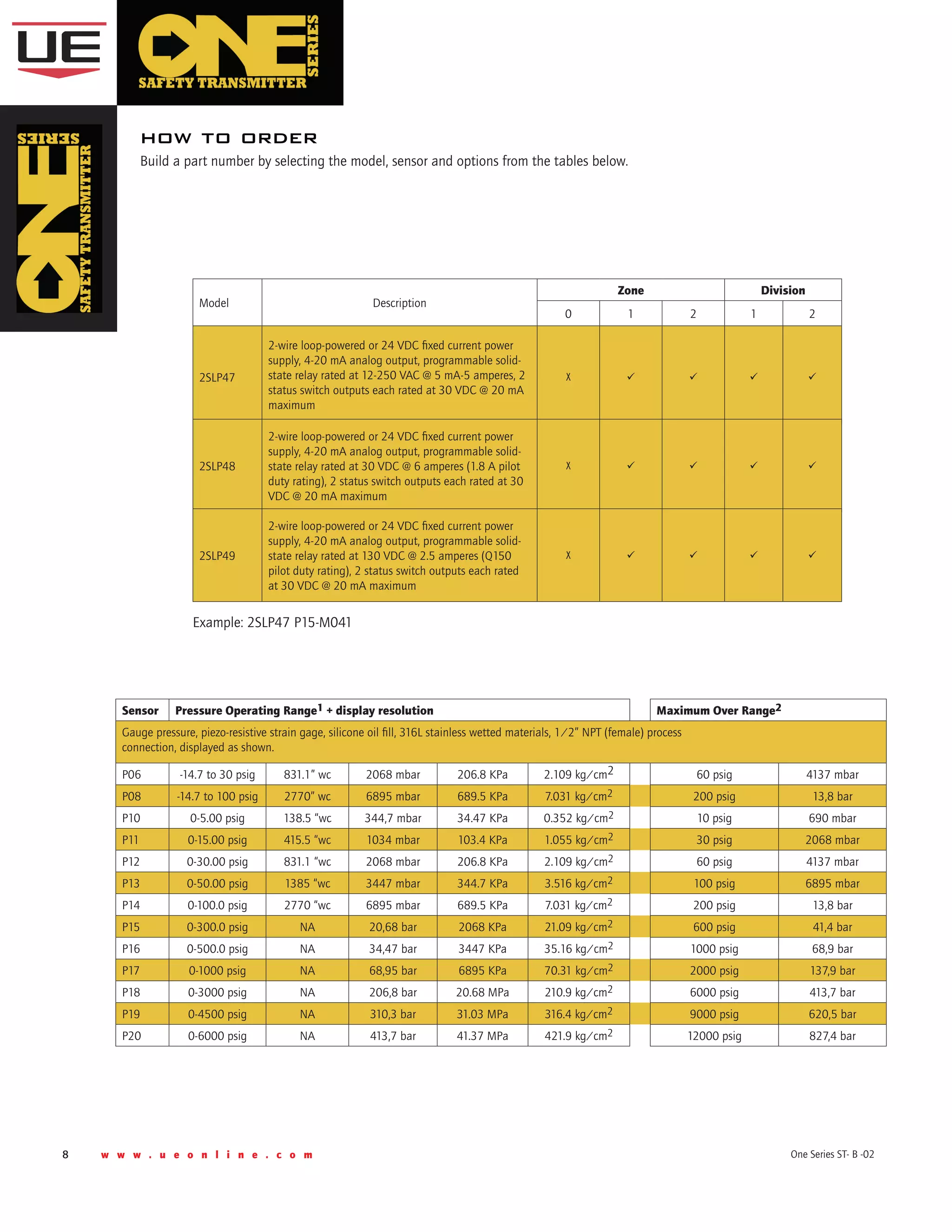

![w w w . u e o n l i n e . c o m 11One Series ST- B -02
ONE Series Safety Transmitter
temperature sensors and fittings compatibility chart
W073 W0741.77"
Ø0.250"
2.285"
Ø0.125"
2.36"
Model (Table 1)
W073
1/2” NPT compression fitting with
ferrule to fit 0.25” sensor sheath
W074
1/2” NPT union connection to fit 0.125” sensor extension
cable
2SLP TLx TRx, THx, TCx
3/4
[19mm]
1
[25.4mm]
2 1/2
[63.5mm]
1/4
[6.4mm]
1/2 NPT
L
P Q
U
Ø.260
BORE
Ø1/2
[12.7mm]
Thermowell
UE Part #
Length (L)
Inches
Local Temperature Sensors w/
0.25” Sensor Sheath1
Remote
Temperature
Sensors w/
0.125” Diameter
MI Cable1
P (NPT) Q U TL1 (4”) TL2 (6”) TL3 (10”) TR, TH & TC
1S260L2.5-316 2.5 1/2 5/8 1 W073 W073 W073 W074
1S260 L4-316 4 1/2 5/8 2.5 NA W073 W073 W074
1S260 L4.5-316 4.5 1/2 5/8 3 NA W073 W073 W074
1S260 L5.5-316 5.5 1/2 5/8 4 NA NA W073 W074
1S260 L6-316 6 1/2 5/8 4.5 NA NA W073 W074
1S260 L6.5-316 6.5 1/2 5/8 5 NA NA W073 W074
1S260 L9-316 9 1/2 5/8 7.5 NA NA NA W074
1S260 L9.5-316 9.5 1/2 5/8 8 NA NA NA W074
1S260 L12-316 12 1/2 5/8 10.5 NA NA NA W074
1S260 L15-316 15 1/2 5/8 13.5 NA NA NA W074
1S260 L18-316 18 1/2 5/8 16.5 NA NA NA W074
1S260 L24-316 24 1/2 5/8 22.5 NA NA NA W074
2S260L2.5-316 2.5 3/4 3/4 1 W073 W073 W073 W074
2S260 L4-316 4 3/4 3/4 2.5 NA W073 W073 W074
2S260 L6-316 6 3/4 3/4 4.5 NA NA W073 W074
2S260 L9-316 9 3/4 3/4 7.5 NA NA NA W074
2S260 L12-316 12 3/4 3/4 10.5 NA NA NA W074
2S260 L15-316 15 3/4 3/4 13.5 NA NA NA W074
2S260 L18-316 18 3/4 3/4 16.5 NA NA NA W074
2S260 L24-316 24 3/4 3/4 22.5 NA NA NA W074
fittings for Thermowells
0.375 REF
0.250
REF
2.50
REF
SENSOR
THERMOWELL ADAPTER
thermowell Adapter option W081 Thermowell](https://image.slidesharecdn.com/one-series-safety-transmitter-switch-180404191657/75/One-Series-Safety-Transmitter-Pressure-and-Temperature-Transmitter-Switch-11-2048.jpg)
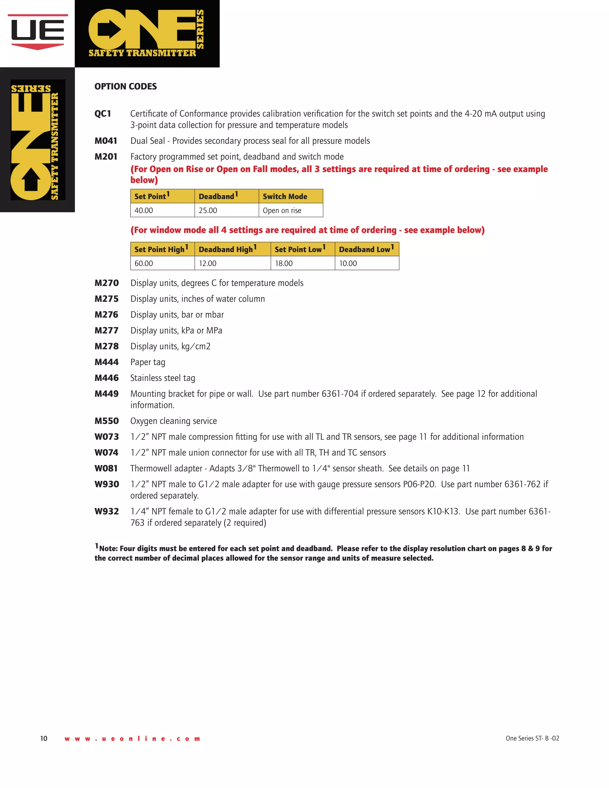
![12 w w w . u e o n l i n e . c o m One Series ST- B -02
2" PIPE
(NOT INCLUDED)
USE 11/32 WIDE SLOTS FOR
WALL OR PIPE MOUNTING
(4 PL)
1X ENCLOSURE SHOWN
(REFERENCE ONLY)
1/4-20
MOUNTING SCREW
QTY (4)
A
C
C
B
B
B
B
PIPE CLAMP NUT
QTY (4)
1/4 LOCKWASHER
QTY (4)
1/4-20 NUT
QTY (4)
PIPE MOUNTING CLAMPS
QTY (2)
A
dimensional drawings
enclosure AND SENSOR details
Wall or Pipe Mounting Bracket
Option M449 or part #6361-704
WARNING: The One Series unit must be
secured to a wall or pipe. Do not use the
sensor to support the instrument. Contact
UE Technical Support at 617-923-6977 or
email at techsupport@ueonline.com.
8.7"
[220.98 mm]
5.3"
[135.62 mm]
1/2 NPT
Pressure
Connection
1/8 NPT
Breather
vent
2.3"
[58.42 mm]
Shown with gauge pressure sensor and Dual Seal option M041
2.9"
[74.48 mm]
4.7"
[119.2 mm]](https://image.slidesharecdn.com/one-series-safety-transmitter-switch-180404191657/75/One-Series-Safety-Transmitter-Pressure-and-Temperature-Transmitter-Switch-12-2048.jpg)
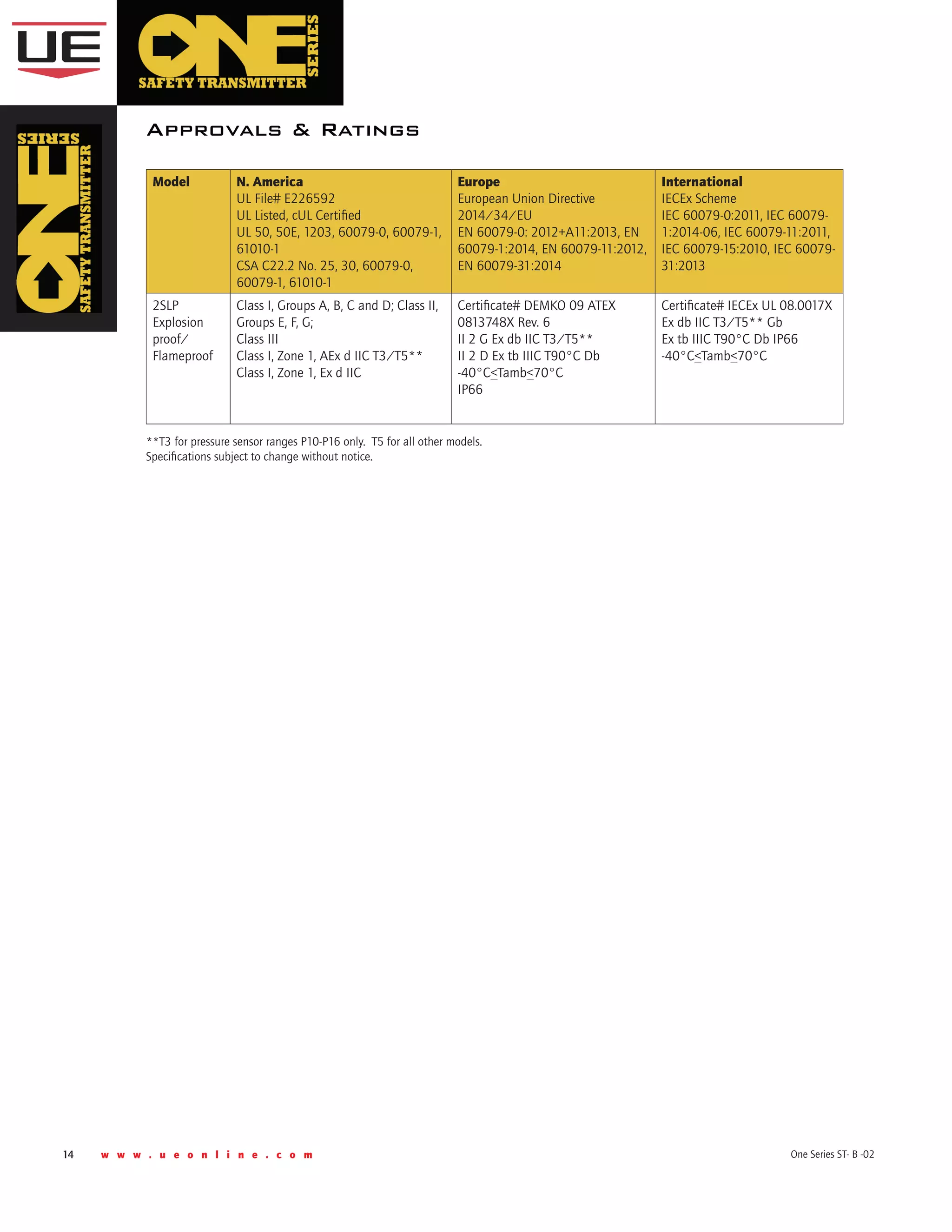
![w w w . u e o n l i n e . c o m 13One Series ST- B -02
ONE Series Safety Transmitter
4.50
[114.3mm]
Ø0.250
[6.4mm]
2.50
[63.5mm]
L 2.00
[50.8mm]
4.50
[114.3mm]
Ø0.125
[3.2mm]
0.50
[12.7mm]
L
0.50
[12.7mm]
L NUN 4.50
[114.3mm]
0.25
[6.35mm]
SPRING
LOAD
TL1-TL3 Sensors
Remote sensors
TTC Sensors
Ø0.250
[6.4mm]
Ø0.250
[6.4mm] L=60”max.,NUN=4”to 10”in 1”increments
TEMPERATURE sensors
DIFFERENTIAL
Pressure SENSORS
GAUGE
PRESSURE SENSORS
1.06
[26.9mm]
1/2”-14 NPT (FEMALE)
1/4”-18 NPT (MALE)
BOTH ENDS3.0
[76.2mm]
1.06
[26.9mm]
dimensional drawings (continued)](https://image.slidesharecdn.com/one-series-safety-transmitter-switch-180404191657/75/One-Series-Safety-Transmitter-Pressure-and-Temperature-Transmitter-Switch-13-2048.jpg)


The One Series Safety Transmitter is designed for monitoring pressure and temperature with features that enhance safety, uptime, and compatibility, meeting SIL 2 and SIL 3 safety standards. It includes rapid response capabilities for emergency shutdowns and programmable features for alarms, ensuring reliable operation in various harsh environments. With self-diagnostics and a robust design, this transmitter can be utilized for diverse applications such as pumps, compressors, and lubricating oil monitoring.


