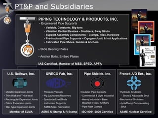
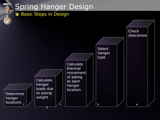
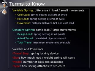
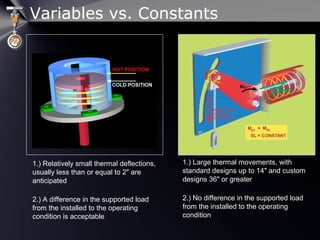
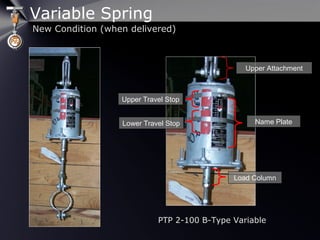
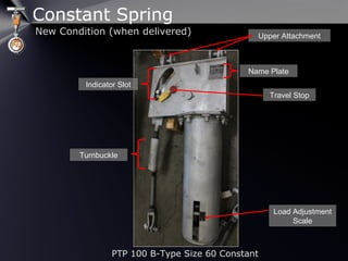
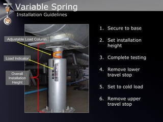
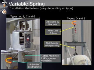
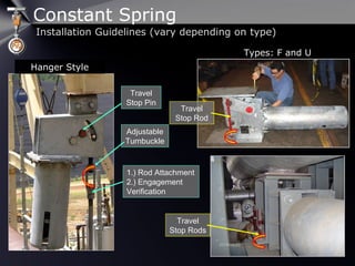
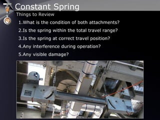
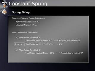
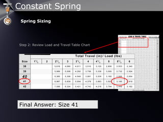
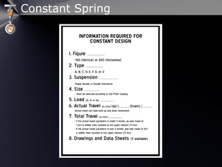
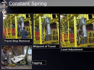
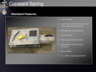
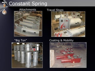
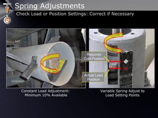
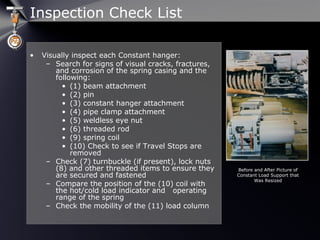
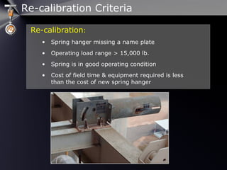
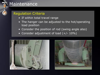
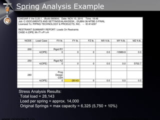
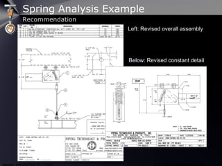
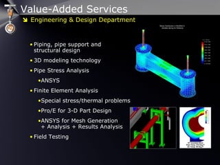
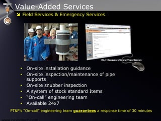
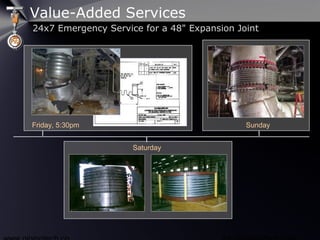
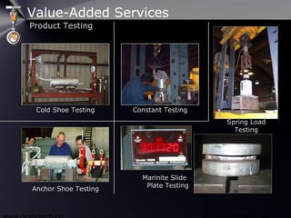
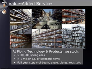
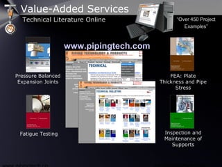
Piping Technology & Products, Inc.
and wholly owned subsidiaries:
US Bellows Sweco Fab Pipe Shields
Anchor/Darling Ent.
Presents:
Engineered Spring SupportsEngineered Spring Supports
A Practical, Hands-on Approach
Presenter: Jerry Godina
Attention Attendees: to listen to the audio portion,
check that your speakers or headset are on and turned
up OR dial the number and use the access code listed
in your confirmation email.
Attention P.E.’s: this Webinar is worth 1 PDH credit for
TX P.E.’s (send request to enews@pipingtech.com)
PT&P and Subsidiaries
U.S. Bellows, Inc.
 Metallic Expansion Joints
 Thin-Wall and Thick-Wall
 Rectangular Expansion Joints
 Fabric Expansion Joints
 Slip-Type Expansion Joints
PIPING TECHNOLOGY & PRODUCTS, INC.
- Engineered Pipe Supports
- Variable, Constants, Big-tons
- Vibration Control Devices – Snubbers, Sway Struts
- Support Assembly Components – Clamps, misc. Hardware
- Pre-insulated Pipe Supports – Cryogenic/cold & Hot Applications
- Fabricated Pipe Shoes, Guides & Anchors
- Slide Bearing Plates
- Anchor Bolts, Embed Plates
IAS Certified, Member of MSS, SPED, APFA
Member of EJMA
SWECO Fab, Inc.
 Pressure Vessels
 Pig Launchers/Receivers
 Spectacle/Line Blinds
 Instrument Supports
 ASME/Misc. Fabrication
ASME U-Stamp & R-Stamp
Pipe Shields, Inc.
Insulated Pipe Supports
 Commercial & Light Industrial
 Heavy Industrial – Base
Mounted Types, Anchors
 Pipe Riser Clamps
ISO 9001-2000 Certified
Fronek A/D Ent., Inc.
 Hydraulic Snubbers
- Short & Adjustable Strut
 Mechanical Snubbers
 dynA/Damp Compensating
Strut
ASME Nuclear Certified
Spring Hanger Design
Calculate
hanger
loads due
to piping
weight
Calculate
thermal
movement
of piping
at each
hanger
location
Determine
hanger
locations
Select
hanger
type
Check
clearances
1 2 3 41 2 3 4
55
 Basic Steps in Design
Terms to Know
Variable Spring: difference in load / small movements
• Cold Load: spring setting at start of cycle
• Hot Load: spring setting at end of cycle
• Movement: distance between hot and cold load
Constant Spring: same load / large movements
• Design Load: spring setting at all points
• Actual Travel: calculated pipe movement
• Total Travel: maximum movement available
Variable and Constants
•Travel Stop: spring locking device
•Size: how much load / weight spring will carry
•Model: number of coils and sequence
•Type: how spring attaches to structure
Variables vs. Constants
1.) Relatively small thermal deflections,
usually less than or equal to 2" are
anticipated
2.) A difference in the supported load
from the installed to the operating
condition is acceptable
1.1.) Large thermal movements, with
standard designs up to 14" and custom
designs 36" or greater
2.2.) No difference in the supported load
from the installed to the operating
condition
Upper Travel Stop
Name Plate
Upper Attachment
Lower Travel Stop
Load Column
Variable Spring
New Condition (when delivered)
PTP 2-100 B-Type Variable
Travel Stop
Name Plate
Upper Attachment
Indicator Slot
Turnbuckle
Constant Spring
New Condition (when delivered)
PTP 100 B-Type Size 60 Constant
Load Adjustment
Scale
Variable Spring
Installation Guidelines
Adjustable Load Column
Overall
Installation
Height
Load Indicator
1. Secure to base
2. Set installation
height
3. Complete testing
4. Remove lower
travel stop
5. Set to cold load
6. Remove upper
travel stop
Variable Spring
Installation Guidelines (vary depending on type)
Types: A, B, C and G
Types: D and E
1.) Rod Attachment
2.) Engagement
Verification
Adjustable
Load Column
Adjustable by
Hex Nuts
Fixed Load
Column
Rod Extends
Through Spring
Variable Spring
Things to Review
1. What is the condition of both
attachments?
2. Is the spring over-loaded or
under-loaded?
3. Is the spring at correct load
set point?
4. Any interference during
operation?
5. Any visible damage?
Total Deflection = ½∙Y
Total Deflection = Y
Total Deflection = 2∙Y
Total Deflection = 3∙Y
Total Deflection = 4∙Y
Design Features: Spring Configurations
Variable Spring
Spring Supports Load & Travel Table
Spring Sizing
Spring Supports Load and Travel Table
Variable Spring
Step 1: Determine a theoretical spring rate
∆ Load / Movement
Given the following design parameters:
A.) Operating Load: 3000
B.) Installed Load: 3300
C.) Movement: ½"
3300-3000
½"
600
Step 2: Review Load and Travel Table Chart
Spring Sizing
Variable Spring
VARIABILITY = (Spring rate ∙ movement ) /Operating Load
Step 3: Review Load and Travel Table Chart
Step 4: Check Variability Factor
VARIABILITY = (600 ∙ ½") / 3000 0.1 equal to 10% ≤ 25%
Final Answer: PTP-2-130
Spring Sizing
Variable Spring
www.pipingtech.com 
Check Hot & Cold Loads
Compress Spring
to Cold Load
Compress Spring
to Hot Load
Spring Loading/Assembly
Compress Spring to Cold Load
& Place in Travel Stops
Remove Spring & Move to
Table Using Hoist
Measure and Adjust Load
Flange Height if Necessary
Variable Spring
www.pipingtech.com 
Load Flange
Load Tag: Both Hot (red)
and Cold (white) Load
Indicators
Installation Instructions
Travel Stops (loaded to your
pre-defined cold load)
Hot-Dipped Galvanized
Adjustable Load Column
(F-Can)
Max. Hydro-Test =
2x Operating Load
Standard Features
Standard Features
B-Type Variable Springs
F-Type Variables
Variable Spring
www.pipingtech.com 
Lifting Lugs
Upper & Lower Limit Stops
Collars
Special Paint
Guided Load Columns
Extended Load Columns
Chained Travel Stops
Jacking Bolts
Slide Plates
Extended Load Column Special Paint
Chained Travel StopsSlide Plates
Special Features
Special Features
Variable Spring
Constant Spring
Installation Guidelines
1. Secure to stationary
attachment
2. Set installation
height
3. Complete testing
4. Set to cold position
5. Remove travel stop
Constant Spring
Installation Guidelines (vary depending on type)
1.) Rod Attachment
2.) Engagement
Verification
Adjustable
Turnbuckle
Travel
Stop Pin
Hanger Style
Types: F and U
Travel
Stop Rod
Travel
Stop Rods
Constant Spring
Things to Review
1.What is the condition of both attachments?
2.Is the spring within the total travel range?
3.Is the spring at correct travel position?
4.Any interference during operation?
5.Any visible damage?
www.pipingtech.com 
Given the Following Design Parameters:
a.) Operating Load: 3000 lb.
b.) Actual Travel: 4 ⅜" up
Step 1: Determine Total Travel:
Rounded up to nearest ½"
a.) When Actual Travel is < 5"
Total Travel = Actual Travel + 1"
b.) When Actual Travel is ≥ 5"
Total Travel = Actual Travel + 20% Rounded up to nearest ½"
Example: Total Travel = 4 ⅜" + 1" = 5 ⅜" 5 ½"
Spring Sizing
Constant Spring
www.pipingtech.com 
Step 2: Review Load and Travel Table Chart
Final Answer: Size 41
Spring Sizing
Constant Spring
www.pipingtech.com 
Constant Spring
www.pipingtech.com 
Travel Stop Removal
Midpoint of Travel
Load Adjustment
Tagging
Constant Spring
www.pipingtech.com 
• Load Flange
• Load Tag: Both Hot (red) and
Cold (white) Movement
• Installation Instructions
• Travel Stops
• Hot-Dipped Galvanized
• Adjustable Load Column
(F-Can)
• Pre-Loaded
• +/- 10% Load Adjustment
Standard Features
Constant Spring
www.pipingtech.com 
Attachments Travel Stops
“Big Ton” Coating & Mobility
Constant Spring
Spring Adjustments
Check Load or Position Settings: Correct if Necessary
Constant Load Adjustment:
Minimum 10% Available
Variable Spring Adjust to
Load Setting Points
Required
Cold Position
Actual Load
Position
• Visually inspect each Constant hanger:
– Search for signs of visual cracks, fractures,
and corrosion of the spring casing and the
following:
• (1) beam attachment
• (2) pin
• (3) constant hanger attachment
• (4) pipe clamp attachment
• (5) weldless eye nut
• (6) threaded rod
• (9) spring coil
• (10) Check to see if Travel Stops are
removed
– Check (7) turnbuckle (if present), lock nuts
(8) and other threaded items to ensure they
are secured and fastened
– Compare the position of the (10) coil with
the hot/cold load indicator and operating
range of the spring
– Check the mobility of the (11) load column
Before and After Picture of
Constant Load Support that
Was Resized
Inspection Check List
Re-calibration:
• Spring hanger missing a name plate
• Operating load range > 15,000 lb.
• Spring is in good operating condition
• Cost of field time & equipment required is less
than the cost of new spring hanger
Re-calibration Criteria
Maintenance
Regulation Criteria
• If within total travel range
• The hanger can be adjusted to the hot/operating
load position
• Consider the position of rod (swing angle also)
• Consider adjustment of load (+/- 10%)
On-Site Survey & Inspection – Constant Spring
Replacement Criteria:
• Signs of excessive corrosion or fatigue
• Rust damage of entire unit
• Modifications to operating conditions
• Consider condition of components (cam
mechanisms, bearings, etc.)
Field Examples
Maintenance - Replace
• Lines/equipment must have a temporary support while
repairs are made
• Re-install travel stops when the line is taken out of
operation (shutdown) to prevent line/equipment
movement and possible readjustment of the springs
• If re-calibration is recommended and name plate is
missing, the variable spring should be stenciled at the
proper installed and operating positions or provide these
loads
• Remove spring hanger assembly
Shutdown/Isolation Procedures
Spring Analysis Example
Original Design
•Horizontal Constants
•5,750 lb. Load
•8-1/2” Total Travel
•B-Type
Spring Analysis Example
Stress Analysis Results:
•Total load = 28,143
•Load per spring = approx. 14,000
•Original Springs = max capacity = 6,325 (5,750 + 10%)
Spring Analysis Example
Left: Revised overall assembly
Below: Revised constant detail
Recommendation
Value-Added Services
• Piping, pipe support and
structural design
• 3D modeling technology
• Pipe Stress Analysis
•ANSYS
• Finite Element Analysis
•Special stress/thermal problems
•Pro/E for 3-D Part Design
•ANSYS for Mesh Generation
+ Analysis + Results Analysis
• Field Testing
 Engineering & Design Department
Value-Added Services
• On-site installation guidance
• On-site inspection/maintenance of pipe
supports
• On-site snubber inspection
• A system of stock standard Items
• “On-call” engineering team
• Available 24x7
PT&P’s “On-call” engineering team guarantees a response time of 30 minutes
 Field Services & Emergency Services
Friday, 5:30pm
Saturday
Sunday
Value-Added Services
24x7 Emergency Service for a 48" Expansion Joint
Cold Shoe Testing Constant Testing
Marinite Slide
Plate Testing
Spring Load
Testing
Anchor Shoe Testing
Value-Added Services
Product Testing
• > 30,000 spring coils
• > 1 million Lb. of standard items
• Full year supply of beam, angle, plates, rods…etc.
At Piping Technology & Products, we stock:
Value-Added Services
Inventory & Stocking Capabilities
www.pipingtech.com
Fatigue Testing
Pressure Balanced
Expansion Joints
FEA: Plate
Thickness and Pipe
Stress
Inspection and
Maintenance of
Supports
“Over 450 Project
Examples”
Value-Added Services
Technical Literature Online
Thank You for Attending…
Engineered Spring SupportsEngineered Spring Supports
(Practical, Hands-on Approach)(Practical, Hands-on Approach)
Please send any additional questions or inquiries to
info@pipingtech.com
Useful Links:
• Online Quote: www.pipingtech.com/quote
• Online Catalog: www.pipingtech.com/catalog
• Technical Webinars: www.pipingtech.com/webinar
• Blog: www.pipingtech.com/blog

Engineered Spring Supports (Practical, Hands-on Approach) Webinar

  • 1.
    Piping Technology &Products, Inc. and wholly owned subsidiaries: US Bellows Sweco Fab Pipe Shields Anchor/Darling Ent. Presents: Engineered Spring SupportsEngineered Spring Supports A Practical, Hands-on Approach Presenter: Jerry Godina Attention Attendees: to listen to the audio portion, check that your speakers or headset are on and turned up OR dial the number and use the access code listed in your confirmation email. Attention P.E.’s: this Webinar is worth 1 PDH credit for TX P.E.’s (send request to enews@pipingtech.com)
  • 2.
    PT&P and Subsidiaries U.S.Bellows, Inc.  Metallic Expansion Joints  Thin-Wall and Thick-Wall  Rectangular Expansion Joints  Fabric Expansion Joints  Slip-Type Expansion Joints PIPING TECHNOLOGY & PRODUCTS, INC. - Engineered Pipe Supports - Variable, Constants, Big-tons - Vibration Control Devices – Snubbers, Sway Struts - Support Assembly Components – Clamps, misc. Hardware - Pre-insulated Pipe Supports – Cryogenic/cold & Hot Applications - Fabricated Pipe Shoes, Guides & Anchors - Slide Bearing Plates - Anchor Bolts, Embed Plates IAS Certified, Member of MSS, SPED, APFA Member of EJMA SWECO Fab, Inc.  Pressure Vessels  Pig Launchers/Receivers  Spectacle/Line Blinds  Instrument Supports  ASME/Misc. Fabrication ASME U-Stamp & R-Stamp Pipe Shields, Inc. Insulated Pipe Supports  Commercial & Light Industrial  Heavy Industrial – Base Mounted Types, Anchors  Pipe Riser Clamps ISO 9001-2000 Certified Fronek A/D Ent., Inc.  Hydraulic Snubbers - Short & Adjustable Strut  Mechanical Snubbers  dynA/Damp Compensating Strut ASME Nuclear Certified
  • 3.
    Spring Hanger Design Calculate hanger loadsdue to piping weight Calculate thermal movement of piping at each hanger location Determine hanger locations Select hanger type Check clearances 1 2 3 41 2 3 4 55  Basic Steps in Design
  • 4.
    Terms to Know VariableSpring: difference in load / small movements • Cold Load: spring setting at start of cycle • Hot Load: spring setting at end of cycle • Movement: distance between hot and cold load Constant Spring: same load / large movements • Design Load: spring setting at all points • Actual Travel: calculated pipe movement • Total Travel: maximum movement available Variable and Constants •Travel Stop: spring locking device •Size: how much load / weight spring will carry •Model: number of coils and sequence •Type: how spring attaches to structure
  • 5.
    Variables vs. Constants 1.)Relatively small thermal deflections, usually less than or equal to 2" are anticipated 2.) A difference in the supported load from the installed to the operating condition is acceptable 1.1.) Large thermal movements, with standard designs up to 14" and custom designs 36" or greater 2.2.) No difference in the supported load from the installed to the operating condition
  • 6.
    Upper Travel Stop NamePlate Upper Attachment Lower Travel Stop Load Column Variable Spring New Condition (when delivered) PTP 2-100 B-Type Variable
  • 7.
    Travel Stop Name Plate UpperAttachment Indicator Slot Turnbuckle Constant Spring New Condition (when delivered) PTP 100 B-Type Size 60 Constant Load Adjustment Scale
  • 8.
    Variable Spring Installation Guidelines AdjustableLoad Column Overall Installation Height Load Indicator 1. Secure to base 2. Set installation height 3. Complete testing 4. Remove lower travel stop 5. Set to cold load 6. Remove upper travel stop
  • 9.
    Variable Spring Installation Guidelines(vary depending on type) Types: A, B, C and G Types: D and E 1.) Rod Attachment 2.) Engagement Verification Adjustable Load Column Adjustable by Hex Nuts Fixed Load Column Rod Extends Through Spring
  • 10.
    Variable Spring Things toReview 1. What is the condition of both attachments? 2. Is the spring over-loaded or under-loaded? 3. Is the spring at correct load set point? 4. Any interference during operation? 5. Any visible damage?
  • 11.
    Total Deflection =½∙Y Total Deflection = Y Total Deflection = 2∙Y Total Deflection = 3∙Y Total Deflection = 4∙Y Design Features: Spring Configurations Variable Spring
  • 12.
    Spring Supports Load& Travel Table Spring Sizing Spring Supports Load and Travel Table Variable Spring
  • 13.
    Step 1: Determinea theoretical spring rate ∆ Load / Movement Given the following design parameters: A.) Operating Load: 3000 B.) Installed Load: 3300 C.) Movement: ½" 3300-3000 ½" 600 Step 2: Review Load and Travel Table Chart Spring Sizing Variable Spring
  • 14.
    VARIABILITY = (Springrate ∙ movement ) /Operating Load Step 3: Review Load and Travel Table Chart Step 4: Check Variability Factor VARIABILITY = (600 ∙ ½") / 3000 0.1 equal to 10% ≤ 25% Final Answer: PTP-2-130 Spring Sizing Variable Spring
  • 15.
    www.pipingtech.com  Check Hot& Cold Loads Compress Spring to Cold Load Compress Spring to Hot Load Spring Loading/Assembly Compress Spring to Cold Load & Place in Travel Stops Remove Spring & Move to Table Using Hoist Measure and Adjust Load Flange Height if Necessary Variable Spring
  • 16.
    www.pipingtech.com  Load Flange LoadTag: Both Hot (red) and Cold (white) Load Indicators Installation Instructions Travel Stops (loaded to your pre-defined cold load) Hot-Dipped Galvanized Adjustable Load Column (F-Can) Max. Hydro-Test = 2x Operating Load Standard Features Standard Features B-Type Variable Springs F-Type Variables Variable Spring
  • 17.
    www.pipingtech.com  Lifting Lugs Upper& Lower Limit Stops Collars Special Paint Guided Load Columns Extended Load Columns Chained Travel Stops Jacking Bolts Slide Plates Extended Load Column Special Paint Chained Travel StopsSlide Plates Special Features Special Features Variable Spring
  • 18.
    Constant Spring Installation Guidelines 1.Secure to stationary attachment 2. Set installation height 3. Complete testing 4. Set to cold position 5. Remove travel stop
  • 19.
    Constant Spring Installation Guidelines(vary depending on type) 1.) Rod Attachment 2.) Engagement Verification Adjustable Turnbuckle Travel Stop Pin Hanger Style Types: F and U Travel Stop Rod Travel Stop Rods
  • 20.
    Constant Spring Things toReview 1.What is the condition of both attachments? 2.Is the spring within the total travel range? 3.Is the spring at correct travel position? 4.Any interference during operation? 5.Any visible damage?
  • 21.
    www.pipingtech.com  Given theFollowing Design Parameters: a.) Operating Load: 3000 lb. b.) Actual Travel: 4 ⅜" up Step 1: Determine Total Travel: Rounded up to nearest ½" a.) When Actual Travel is < 5" Total Travel = Actual Travel + 1" b.) When Actual Travel is ≥ 5" Total Travel = Actual Travel + 20% Rounded up to nearest ½" Example: Total Travel = 4 ⅜" + 1" = 5 ⅜" 5 ½" Spring Sizing Constant Spring
  • 22.
    www.pipingtech.com  Step 2:Review Load and Travel Table Chart Final Answer: Size 41 Spring Sizing Constant Spring
  • 23.
  • 24.
    www.pipingtech.com  Travel StopRemoval Midpoint of Travel Load Adjustment Tagging Constant Spring
  • 25.
    www.pipingtech.com  • LoadFlange • Load Tag: Both Hot (red) and Cold (white) Movement • Installation Instructions • Travel Stops • Hot-Dipped Galvanized • Adjustable Load Column (F-Can) • Pre-Loaded • +/- 10% Load Adjustment Standard Features Constant Spring
  • 26.
    www.pipingtech.com  Attachments TravelStops “Big Ton” Coating & Mobility Constant Spring
  • 27.
    Spring Adjustments Check Loador Position Settings: Correct if Necessary Constant Load Adjustment: Minimum 10% Available Variable Spring Adjust to Load Setting Points Required Cold Position Actual Load Position
  • 28.
    • Visually inspecteach Constant hanger: – Search for signs of visual cracks, fractures, and corrosion of the spring casing and the following: • (1) beam attachment • (2) pin • (3) constant hanger attachment • (4) pipe clamp attachment • (5) weldless eye nut • (6) threaded rod • (9) spring coil • (10) Check to see if Travel Stops are removed – Check (7) turnbuckle (if present), lock nuts (8) and other threaded items to ensure they are secured and fastened – Compare the position of the (10) coil with the hot/cold load indicator and operating range of the spring – Check the mobility of the (11) load column Before and After Picture of Constant Load Support that Was Resized Inspection Check List
  • 29.
    Re-calibration: • Spring hangermissing a name plate • Operating load range > 15,000 lb. • Spring is in good operating condition • Cost of field time & equipment required is less than the cost of new spring hanger Re-calibration Criteria
  • 30.
    Maintenance Regulation Criteria • Ifwithin total travel range • The hanger can be adjusted to the hot/operating load position • Consider the position of rod (swing angle also) • Consider adjustment of load (+/- 10%)
  • 31.
    On-Site Survey &Inspection – Constant Spring Replacement Criteria: • Signs of excessive corrosion or fatigue • Rust damage of entire unit • Modifications to operating conditions • Consider condition of components (cam mechanisms, bearings, etc.)
  • 32.
  • 33.
    • Lines/equipment musthave a temporary support while repairs are made • Re-install travel stops when the line is taken out of operation (shutdown) to prevent line/equipment movement and possible readjustment of the springs • If re-calibration is recommended and name plate is missing, the variable spring should be stenciled at the proper installed and operating positions or provide these loads • Remove spring hanger assembly Shutdown/Isolation Procedures
  • 34.
    Spring Analysis Example OriginalDesign •Horizontal Constants •5,750 lb. Load •8-1/2” Total Travel •B-Type
  • 35.
    Spring Analysis Example StressAnalysis Results: •Total load = 28,143 •Load per spring = approx. 14,000 •Original Springs = max capacity = 6,325 (5,750 + 10%)
  • 36.
    Spring Analysis Example Left:Revised overall assembly Below: Revised constant detail Recommendation
  • 37.
    Value-Added Services • Piping,pipe support and structural design • 3D modeling technology • Pipe Stress Analysis •ANSYS • Finite Element Analysis •Special stress/thermal problems •Pro/E for 3-D Part Design •ANSYS for Mesh Generation + Analysis + Results Analysis • Field Testing  Engineering & Design Department
  • 38.
    Value-Added Services • On-siteinstallation guidance • On-site inspection/maintenance of pipe supports • On-site snubber inspection • A system of stock standard Items • “On-call” engineering team • Available 24x7 PT&P’s “On-call” engineering team guarantees a response time of 30 minutes  Field Services & Emergency Services
  • 39.
    Friday, 5:30pm Saturday Sunday Value-Added Services 24x7Emergency Service for a 48" Expansion Joint
  • 40.
    Cold Shoe TestingConstant Testing Marinite Slide Plate Testing Spring Load Testing Anchor Shoe Testing Value-Added Services Product Testing
  • 41.
    • > 30,000spring coils • > 1 million Lb. of standard items • Full year supply of beam, angle, plates, rods…etc. At Piping Technology & Products, we stock: Value-Added Services Inventory & Stocking Capabilities
  • 42.
    www.pipingtech.com Fatigue Testing Pressure Balanced ExpansionJoints FEA: Plate Thickness and Pipe Stress Inspection and Maintenance of Supports “Over 450 Project Examples” Value-Added Services Technical Literature Online
  • 43.
    Thank You forAttending… Engineered Spring SupportsEngineered Spring Supports (Practical, Hands-on Approach)(Practical, Hands-on Approach) Please send any additional questions or inquiries to info@pipingtech.com Useful Links: • Online Quote: www.pipingtech.com/quote • Online Catalog: www.pipingtech.com/catalog • Technical Webinars: www.pipingtech.com/webinar • Blog: www.pipingtech.com/blog

Editor's Notes

  • #2 Hello everyone, I would like to welcome you to our Webinar on Constant Spring Supports. The Webinar today is hosted by Piping Technology &amp; Products. I am __________________________ and I will be your presenter. Optional: Your normal presenter, Jerry Godina is on a field service call and could not make it today to present, so I will be standing in for him. Also, if you have a question, please feel free to chat it to us during the presentation in the text box you see to the right of the presentation or if you prefer, you can ask questions after the presentation during our “Questions and Answers Session.”
  • #3 For those of you who are unfamiliar with PT&amp;P, I want to quickly go over some background information. If you would like to know more, please visit our “About Us” section at pipingtech.com. Our parent company, Piping Technology &amp; Products, Inc., also known as PT&amp;P, is a member of MSS, SPED, and APFA In business since 1975, Piping Technology &amp; Products, Inc. and its wholly owned subsidiaries (US Bellows, Sweco Fab, Pipe Shields, and Anchor Darling) offer a wide range of engineered products and services for various industries and applications. Our product line is extensive… From engineered pipe supports, expansion joints, pre-insulated pipe supports, and miscellaneous fabrication to various engineering and technical services, PT&amp;P has decades of experience providing products and services for all your engineering and construction needs.
  • #4 Pipe Hangers are designed to control: Longitudinal weight stress in the piping system without creating additional stresses Piping system loads on equipment without limiting or reducing static loads Hanger loads on building structure And physical clearances of hanger components with piping and structure Let’s look at the basic steps in the hanger design: Step 1 is to determine the location of all the hangers Then calculate the hanger loads due to the piping weight Next calculate the thermal movement of the piping at each hangers location Step 4 is to select the hanger type and finally check all clearances
  • #12 The way a variable spring support responds to an applied load depends on the coil or coils inside the casing. Each coil arrangement has a spring rate expressed in units of pounds/inch (or kilograms/millimeters) of compression. The required coil size is determined by load while the required number of coils (length) is determined by the anticipated range of movement. A longer coil or coils placed in series will provide greater travel for similar loads. We use PTP-1, PTP-2, PTP-4, PTP-6, and PTP-8 to designate the five standard coil arrangements we employ to increase the working range of travel of variable supports.
  • #13 The Load and Travel Tables are color-coded to identify the travel and spring rates for each PTP figure number.* These tables can be used to select the PTP Figure Number and size required for a particular application. The twenty-three columns designated 00, 10, 20, ..., 220 identify the size and spring rate of coils used in the variables. The larger numbers have higher spring rates and are used to support greater loads. The recommended working range of loads for each size is shown between the red lines in the tables. The center of the working range is colored blue. Selecting variables with the loads within the working range provides a reserve above and below to insure the coil can function inside the casing. In using the Load and Travel Table to choose the proper variable support, it is best to have the operating (hot) load and an amount and direction of expected movement. Variability is a key criterion in selecting the figure number and size.
  • #14 Example: Given the following design parameters: A.) Operating Load: 3000 B.) Installed Load: 3300 C.) Movement: ½&amp;quot; Step 1: Determine a theoretical spring rate: ∆ Load / Movement  (3300-3000)/ ½&amp;quot;  600 Step 2: Review Load and Travel Table Chart
  • #15 Step 3: Review Load and Travel Table Chart Step 4: Check Variability Factor Variability is the percentage of change in the supporting force between the operating (hot) and installed (cold) positions calculated as shown: VARIABILITY = (Spring rate * movement ) /Operating Load VARIABILITY = (600 ∙ ½&amp;quot;) / 3000  0.1 equal to 10% ≤ 25% Final Answer: PTP-2-130 Good practice, as specified by MSS SP-58, is to choose a support with variability less than or equal to 25%. Always try to choose a variable with the operating (hot) load near the center line (blue) of the working range in the Load and Travel Table. If you have a situation in which you cannot select a standard variable which has both the operating load and the installed load within the working range, contact us and we will help you determine alternatives.
  • #16 For the next three slides, we will go through the steps in loading a spring can. This particular spring can has a cut-away view for demonstration purposes. The first step is to check the hot and cold loads on the assembly drawing. The second step is to compress the spring to solid and release three times total. Then you will need to zero out the load cell before you compress the spring to the specified cold load. Mark the cold load location on the can, then measure for the travel stop length. Next you will need to compress the spring to the specified hot load.
  • #17 Standard Features -Load Flange -Load Tag: Both Hot (red) and Cold (white) Movement -Installation Instructions -Travel Stops -Hot-Dipped Galvanize Finish -Adjustable Load Column (F-Can) -Pre-Loaded Left Picture: Type B Variable Spring Hanger Right Picture: Type F Variables designed for an offshore oil rig: carbon steel with hot-dipped galvanized components (PTP-6, size 90, 3 spring coils with a 7-1/2&amp;quot; working range, load capacity: 950 lb., overall height: 33-1/2&amp;quot;, travel range: 4&amp;quot;, 8-5/8&amp;quot; diameter casing, 13&amp;quot; square base plate, 8&amp;quot; load flange) http://www.pipingtech.com/news/arc_pw_2004/engps2004_04.htm
  • #18 Special Features can be provided if required: --lifting lugs can be helpful for installing large hangers --Upper and lower limit stops --Collars --Special Paint --Guided load columns --Extended load columns --Chained travel stops --Jacking Bolts --Type F PTFE, 25% glass filled
  • #28 Back of a Can, Horizontal with Rod and Hex nuts Coil Adjustment
  • #30 In the case you want to use your existing spring support, re-calibration is an option as long as the support is a constant spring support, in good operating condition, has an operating load range greater than fifteen thousand (15,000) pounds and the cost of field time and equipment is less than the cost of a new spring hanger.
  • #32 LEFT PIC: Constant Support in Jamaica-Travel Pin is Rusted and Decayed
  • #34 A few thoughts during shutdown: Are the lines and equipment temporarily supported while repairs are being made? To prevent having to readjust the spring, I need to re-install the travel stops. If the name plate is missing, stencil the proper installed and operating positions or provide loads for re-calibration.
  • #40 Remove this slide… does not flow when talking about services and then stopping and switching to an example
  • #43 Since we don’t have much time this evening, you may want to check out our website; there you will find a plethora of technical information, including different Tests we carry out, FEA Analysis, and much more.
  • #44 That concludes our Webinar on Constant Spring Supports…. I hope everyone enjoyed the presentation and as a reminder, we have a staff of experts standing by to answer any questions you may have. You can just chat them now while in session until the end of the hour, you can also send them to us by e-mail at info@pipingtech.com