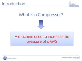
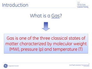
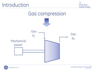
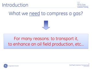
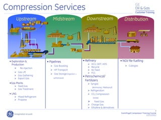
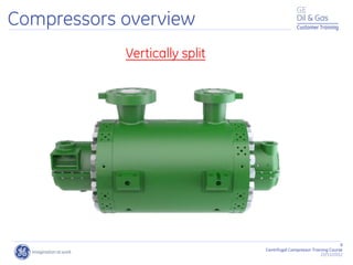
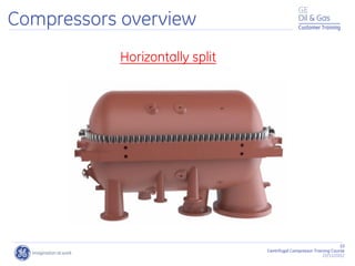
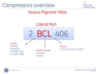
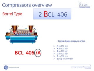
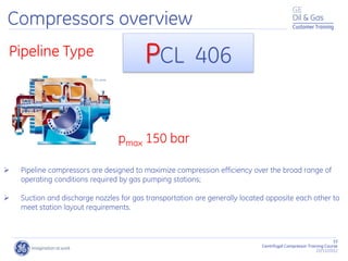
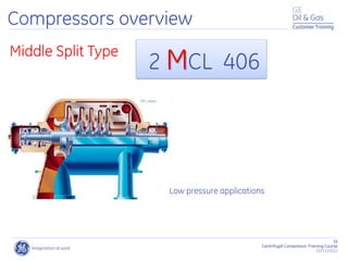
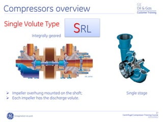
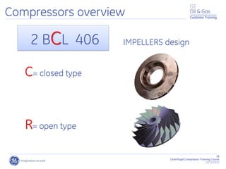
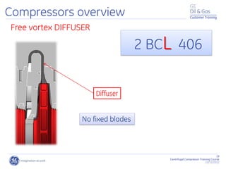
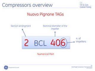
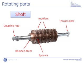
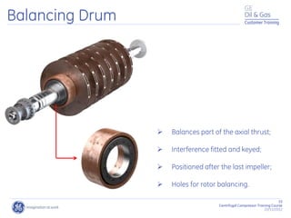
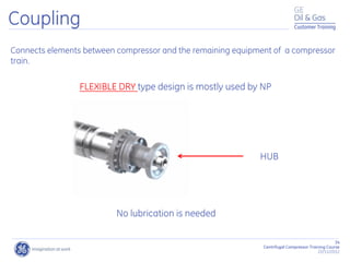
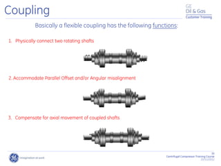
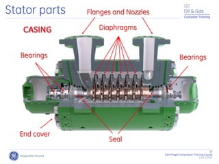
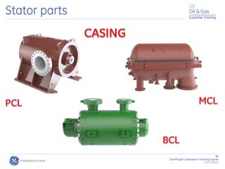
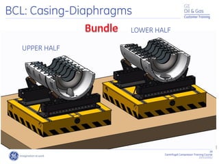
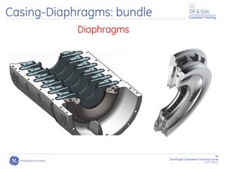
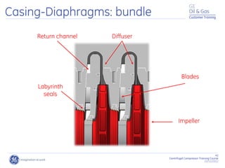
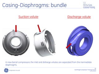
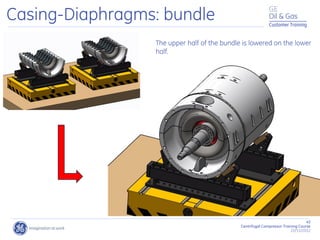
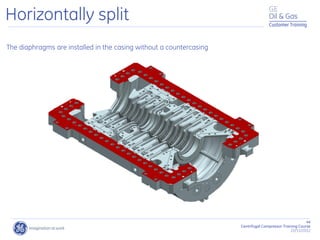
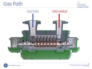
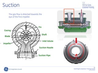
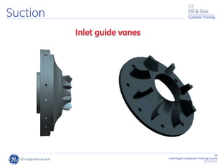
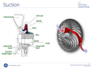
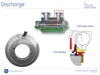
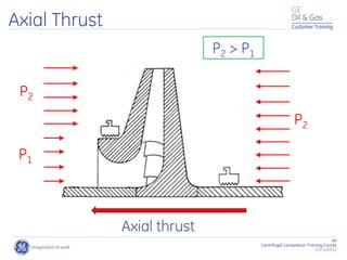
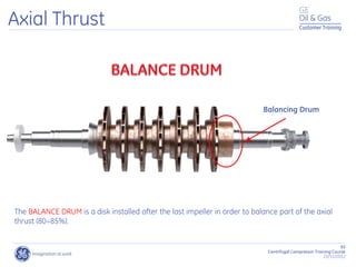
This document provides an overview of centrifugal compressors and their components. It discusses what a compressor and gas are, and how compression is used to transport gas for various oil and gas industry applications. The key components of a centrifugal compressor are described, including the rotating parts like the shaft, impellers, and balance drum, and the static parts such as casings, diaphragms, bearings, seals, and flanges. Designs like vertically split, horizontally split, and single volute compressors are also covered.
Centrifugal compressors work by imparting kinetic energy to a gas stream using an impeller, converting the dynamic energy into increased static pressure. They have advantages like high throughput capacity and efficiency over a wide operating range, but also disadvantages like discharge pressure limitations. Key components include impellers, diffusers, volutes, casings, shafts, bearings, and seals. Surge, a dangerous condition where flow reverses rapidly, must be controlled. Compressors can operate alone or in multi-stage arrangements with intercoolers. Common drivers are steam turbines, electric motors, and gas turbines.
Centrifugal compressor head - Impact of MW and other parametersSudhindra Tiwari
Please read the revised version.
A sequential approach to describe compressor head, pressure, system head and impact of MW and other suction parameters on head.
This document provides an overview of mechanical seal piping plans used by Flowserve's Flow Solutions Division. It summarizes 14 single seal plans and 8 dual/quench/gas seal plans. Each plan page shows a seal end view diagram, description of what the plan is, why it is used, where it is applicable, and tips for preventative maintenance. The plans provide ways to keep mechanical seals running cleanly and cool through circulation of barrier fluids.
This PowerPoint shows an introduction to positive displacement compressors. You will have a brief introduction about the operating principles of reciprocating compressors, the different types of rotary compressors, and techniques for controlling compressor output most important variables.You will learn as well the construction, principal parts, and operation of reciprocating compressors
This document provides an overview of centrifugal compressors. It begins with introductions to potential and kinetic energy as they relate to compression. It then discusses dynamic compressors like centrifugal and axial compressors. The document outlines the major parts of compressors like casings, impellers, diffusers, and seals. It also describes the cooling, lubrication, and safety systems that support compressor operation. Finally, it discusses operating characteristics, configurations like series and parallel, and performance features of compressors.
Gas Turbine Training Power Point -SampleAli Rafiei
The document provides an overview of gas turbine evolution and components. It discusses the development of axial compressors and turbines from the 18th century ideas of John Barber and John Dumball. It then summarizes the key components of modern gas turbines, including compressors, combustion chambers, turbines, lubrication systems, and controls. Examples are given for Siemens SGT600 components like the compressor, combustion chamber, and control modes.
The document provides information about GE's MS 5002 C gas turbine customized for Burlington Resources MLN 405 Project. It contains proprietary information for customer training purposes only. The manual covers theory of operation, maintenance, and drawings of the gas turbine. It was prepared by Elena Casini of GE Oil & Gas and approved by Cesare Sordi, the customer training manager, on March 19, 2007 for the specific customer and job. The manual has sections on theory of operation, operation, maintenance, and drawings of the gas turbine.
This document summarizes a parametric study evaluating design parameters for pulsation dampeners on plunger pumps. The study uses a pulsation model to examine the effects of:
1) Pump system configuration, finding that complex piping can significantly impact pulsations compared to just the pump package.
2) Dampener location, finding pulsations generally increase as the dampener moves farther from the pump, and are still high when located next to the pump due to quarter-wave resonances.
3) Dampener neck geometry, finding pulsations decrease with a larger neck diameter and shorter neck length to maximize the dampener's effect.
The study also examines the impacts of fluid compressibility and
This presentation covers basics of different types of compressor, selection chart , basic terminology, performance curves , over view about associated system.
1. The document discusses the principles and components of a centrifugal compressor, including impellers that impart kinetic energy to gas and diffusers that convert velocity to pressure.
2. It also covers formulas used in centrifugal compression as well as factors that affect the total head such as temperature and molecular weight.
3. The document describes surge and methods to prevent it, noting that an anti-surge controller monitors distance to the surge line and controls a recycle valve to maintain flow above a safe level.
Accumulation and Over-pressure: difference between accumulation and overpressureVarun Patel
Accumulation is pressure above the maximum allowable working pressure that vessel experience during high pressure event. Hence, when we say ‘accumulation’, its mean we are talking about the vessel or equipment.
On the other hand, Overpressure is pressure above the set pressure of the pressure safety valve that PSV experience during high pressure event. Hence, when we say ‘accumulation’, its mean we are talking about the pressure relief valve.
Centrifugal Compressor System Design & SimulationVijay Sarathy
The power point slides focuses on centrifugal compressor design, dynamic simulation including anti surge valve and hot gas bypass requirements. The topics covered are,
Centrifugal Compressor (CC) System Characteristics
Centrifugal Compressor (CC) Drivers
Typical Single Stage System
Start-up Scenario
Shutdown Scenario
Emergency Shutdown (ESD) Scenario
Centrifugal Compressor (CC) System Design Philosophy
Anti-Surge System
Recycle Arrangements
CC Driver Arrangements
General Notes
This document provides information on centrifugal pump classification, installation, maintenance, and troubleshooting. It includes classifications based on ANSI/API standards for overhung, between bearing, and vertically suspended pump designs. The document also details maintenance procedures and checklists for pump systems, mechanical components, electrical systems, diesel engines, and more. Common centrifugal pump problems like low flow are addressed along with potential causes such as air leaks, low speed, and high system head.
- The document discusses sizing pressure safety valves (PSVs) for oil and gas facilities.
- It covers PSV types, causes of chattering, and outlines the step-by-step process for sizing calculations including developing relief scenarios, determining required relief areas, and selecting valve sizes.
- Relief scenarios considered include blocked outlets, thermal expansion, tube rupture, gas blow-by, inlet valve failure, and exterior fires. Relief calculations involve assessing single-phase, two-phase, and transient relief situations.
The document discusses compressor working principles and types. It provides the following key points:
1) There are two basic principles of air or gas compression: positive displacement and dynamic compression. Positive displacement compressors reduce volume to increase pressure while dynamic compressors convert velocity to pressure.
2) Compressor types include centrifugal and reciprocating compressors. Centrifugal compressors use radial diffusers to increase pressure via Bernoulli's principle while reciprocating compressors use pistons in cylinders.
3) Capacity control methods for compressors include inlet guide vanes, blow-off valves, and modulating control to vary output between 100% to 10%. Operating parameters like inlet pressure and temperature influence compressor flow and power requirements
The document discusses different types of heat exchangers including regenerative heat exchangers, plate heat exchangers, and shell and tube heat exchangers. Heat exchangers can be classified based on connecting technique, number of fluids, degree of surface compactness, construction, and flow arrangements such as counter flow, parallel flow, and cross flow. Shell and tube heat exchangers are commonly used in oil refineries and large chemical processes due to their ability to handle higher pressures. They consist of tubes, a shell, baffles, and may vary based on tube characteristics like shape, number, length, diameter, and thickness or the material used for the shell.
This document provides assembly, component, and maintenance details for a floating head heat exchanger. It includes general assembly and cross-sectional views labeling major components like the shell, tube bundle, floating head, and distributor. Step-by-step maintenance procedures are described for activities like removing the bundle, hydrotesting the shell and tube sides, eliminating tube leaks, and final hydrotesting before unit startup. Safety and proper housekeeping during maintenance are emphasized.
Cameron manufactures centrifugal air and gas compressors and provides aftermarket services globally. They offer compressors in their MSG and Turbo-Air series that provide oil-free compression with flexible configurations for a wide range of flows and pressures. Cameron compressors provide advantages over other compressor technologies like being oil-free, compact, and requiring low maintenance.
Thermodynamics deals with the effects of work, heat and energy on systems. It considers macroscopic and microscopic changes. The laws of thermodynamics are:
1) Zeroth law - If two systems are in thermal equilibrium with a third, they are in equilibrium with each other.
2) First law - The change in internal energy of a closed system equals the heat supplied minus the work done.
3) Second law - Heat cannot spontaneously flow from a cold body to a hot body.
4) Third law - The entropy of a system approaches a constant value as the temperature approaches absolute zero.
Types of compressor and application in oil and gas industryajichemix
This presentation covers the type of compressors, its application, capacity control methods, surge control, cooling system, advantage and disadvantage of compressors.
This document discusses lubricants used in thermal power plants. It begins by introducing the importance of selecting the proper lubricant and understanding lubrication theory. It then discusses the fundamentals of lubrication in reducing friction and wear. Different types of lubricating oils and their characteristics like viscosity and additives are explained. Common additives are outlined that improve performance by interacting with machine metals. Grease composition and characteristics are also covered. The document concludes by examining lubricant specifications for steam turbines and other thermal power plant equipment.
The document provides an overview of the operations, renewal plan, people and process safety aspects of the Badak Compressor station. It describes the basic components of the gas turbine, compressor and their supporting systems including air, fuel, lube oil and start systems. Diagrams of the turbine, air flow, fuel and other systems are included. Details are given on the compressor cutaway, bearings, seals, seal oil system, performance curves and overview.
The document is a presentation about industrial compressors used in processing plants. It discusses the main types of compressors, including positive displacement and dynamic compressors. It describes methods of capacity control for different compressor types and flow capacities at varying discharge pressures. Standard speed and flow capacity ranges for compressor drives are also covered. The presentation focuses in detail on centrifugal compressors, explaining their operation and key components like impellers and diffusers. Contact information is provided for questions.
Plan 11 involves recirculation from the pump discharge through a flow control orifice into the seal chamber for flushing and cooling. It can be used for clean, non-polymerizing fluids with moderate temperatures. The orifice size must be carefully calculated for high head applications, with a minimum size of 3mm. Various EagleBurgmann seals can be used with this plan.
This document appears to be a project report submitted by a student named Viralkumar Shaileshkumar Wadiya for their diploma in mechanical engineering. The report documents the student's week-long practical training and visit to Jupiter Technologies Ltd, where they observed production issues including insufficient pressure on compressor heads. The student's report provides information on the company, details of the machines and tools used, products manufactured, and analyzes the identified problem of insufficient pressure on compressor heads.
Improvement of Air-Swirl ratio in 4-stroke diesel engine to improve performan...IRJET Journal
1) The document discusses improving the air-swirl ratio in a 4-stroke diesel engine through modifications to the inlet poppet valve to enhance engine performance and reduce harmful emissions.
2) The researchers designed and 3D modeled a modified inlet poppet valve with four balls attached to the seat surface to disrupt airflow and create turbulence.
3) Experiments were conducted on a single cylinder diesel engine test rig to compare the performance and emissions of the standard and modified inlet valves. The modified valve improved combustion and reduced emissions of hydrocarbons, carbon monoxide and nitrogen oxides but lowered efficiency slightly.
Bomag bw 177 single drum roller service repair manualujdkkdkdmm
This document provides training on the Variocontrol single drum roller. It describes the electric steering system which uses an electronically controlled closed loop with a hydraulic circuit. It includes a steering pump, high pressure filter, steering valve and cylinders. The emergency steering valve is optional. The BOP display panel can diagnose the measuring and control systems. Troubleshooting procedures and components of the exciter and BVC systems are explained.
Bomag bw 213 single drum roller service repair manualujdkdkdmdm
This document provides an overview of the electric steering system used on BOMAG Variocontrol single drum rollers. It describes the key components of the electric steering circuit including the electric steering wheel, ESX control unit, steering valve, steering angle sensor and hydraulic steering circuit. The emergency steering valve is also described as an optional component that can only be operated via a special input code. Troubleshooting information and diagrams of the steering system are provided.
Bomag bw 213 single drum roller service repair manualfjskekazswdmme
This document provides an overview of the electric steering system used on BOMAG Variocontrol single drum rollers. It describes the key components of the electric steering circuit including the electric steering wheel, ESX control unit, steering valve, steering pump, steering cylinders and optional emergency steering valve. The document also provides diagrams of the steering valve and emergency steering valve along with their positions in the hydraulic and electrical systems.
Bomag bw 226 single drum roller service repair manualfjjskdmnenemm
This document provides an overview of the electric steering system used on BOMAG Variocontrol single drum rollers. It describes the key components of the electric steering circuit including the electric steering wheel, ESX control unit, steering valve, steering pump, steering cylinders and optional emergency steering valve. The document also provides diagrams of the steering valve and emergency steering valve along with their component labels and wiring/hydraulic diagram positions for troubleshooting.
Bomag bw 177 single drum roller service repair manualwedsrffcdgdv
This document provides an overview of the electric steering system used on BOMAG Variocontrol single drum rollers. It describes the key components of the electric steering circuit including the electric steering wheel, ESX control unit, steering valve, steering pump, steering cylinders and optional emergency steering valve. The document also provides diagrams of the steering valve and emergency steering valve along with their positions in the hydraulic and electrical systems.
Bomag bw 177 single drum roller service repair manualfjsqazkekdmme
This document provides an overview of the electric steering system used on BOMAG Variocontrol single drum rollers. It describes the key components of the electric steering circuit including the electric steering wheel, ESX control unit, steering valve, steering angle sensor and hydraulic steering circuit. The emergency steering valve is also described as an optional component that can only be activated via an input code. Troubleshooting information and diagrams of the steering circuit and hydraulic system are provided.
Bomag bw 177 single drum rollers service repair manualfjsqazkekdmme
The maintenance table lists maintenance work to be performed on the single drum roller at various intervals. Tasks include checking fluid levels daily, changing engine oil and filters every 500 hours, changing hydraulic oil and filters every 2000 hours, and checking components annually such as the air filters, belts, and scraper adjustments. Thorough and timely maintenance is important to ensure the machine's safety, functionality, and lifetime.
Bomag bw 179 dh single drum rollers service repair manualfjskekdmmem
This document provides technical data and adjustment values for the BW 177 DH Series 4 single drum roller, including specifications for the Deutz diesel engine, hydrostatic travel pump, drum drive motor, vibration pump, steering pump, rear axle, and recommended filling capacities. The machine's serial number range and manufacture dates are also listed to ensure the correct documentation is referenced.
Bomag bw 179 pdh 4 single drum rollers service repair manualfjskekdmmem
This document provides technical data and adjustment values for the BW 177 DH Series 4 single drum roller, including specifications for the Deutz diesel engine, hydrostatic travel pump, drum drive motor, vibration pump, steering pump, rear axle, and recommended filling capacities. The machine's serial number range and manufacture dates are also listed to ensure the correct documentation is referenced.
Bomag bw 177 single drum rollers service repair manualwedsrffcdgdv
The document provides a maintenance table for a single drum roller that outlines maintenance work to be performed at various operating hour intervals. It lists over 40 maintenance items ranging from daily checks of fluid levels to annual tasks like changing engine oil and filters. Performing regular maintenance according to the schedule is important to ensure the machine is ready for demanding construction work and all safety systems function properly.
Bomag bw 179 dh single drum rollers service repair manualujdkdkdmdm
The document provides a maintenance table for a single drum roller that outlines maintenance work to be performed at various operating hour intervals. It lists over 40 maintenance items ranging from daily checks of fluid levels to annual tasks like changing engine oil and filters. Performing regular maintenance according to the schedule is important to ensure the machine is ready for heavy duty work and meets safety standards.
Bomag bw 179 dh single drum rollers service repair manualfjskekazswdmme
The document provides a maintenance table for a single drum roller that outlines maintenance work to be performed at various operating hour intervals. It lists over 40 maintenance items ranging from daily checks of fluid levels to annual tasks like changing engine oil and filters. Performing regular maintenance according to the schedule is important to ensure the machine is ready for demanding construction work and all safety systems function properly.
Bomag bw 177 single drum rollers service repair manualujdkkdkdmm
This document provides technical data and adjustment values for the BW 177 DH Series 4 single drum roller, including specifications for the Deutz diesel engine, hydrostatic travel pump, drum drive motor, vibration pump, steering pump, rear axle, and recommended filling capacities. The machine's serial number range and manufacturer details are given for major components. Technical parameters like power output, displacement volumes, pressure settings, and speed values are listed.
Bomag bw 179 pdh 4 single drum rollers service repair manualfjskekazswdmme
The document provides a maintenance table for a single drum roller that outlines maintenance work to be performed at various operating hour intervals. It lists over 40 maintenance items ranging from daily checks of fluid levels to annual tasks like changing engine oil and filters. Performing regular maintenance according to the schedule is important to ensure the machine is ready for demanding construction work and all safety systems function properly.
Bomag BW 177 Single Drum Rollers Service Repair Manual.pdfkm7seydwuhdw
This document provides technical data and adjustment values for the BW 177 DH Series 4 single drum roller, including specifications for the Deutz diesel engine, hydrostatic travel pump, drum drive motor, vibration pump, steering pump, rear axle, and recommended filling capacities. The machine's serial number range and component manufacturers are also listed. Key specifications include an engine power of 74.9 kW at 2200 rpm, a travel pump maximum displacement of 56 cm3/rev, and a drum drive motor displacement of 60 cm3/rev in stage 1.
Bomag BW 179 PDH-4 Single Drum Rollers Service Repair Manual.pdfkm7seydwuhdw
The document provides a maintenance table for a single drum roller that outlines maintenance work to be performed at various operating hour intervals. It lists over 40 maintenance items ranging from daily checks of fluid levels to annual tasks like changing engine oil and filters. Performing regular maintenance per the schedule is important to ensure the machine is ready for demanding construction work and all safety systems function properly.
An improved modulation technique suitable for a three level flying capacitor ...IJECEIAES
This research paper introduces an innovative modulation technique for controlling a 3-level flying capacitor multilevel inverter (FCMLI), aiming to streamline the modulation process in contrast to conventional methods. The proposed
simplified modulation technique paves the way for more straightforward and
efficient control of multilevel inverters, enabling their widespread adoption and
integration into modern power electronic systems. Through the amalgamation of
sinusoidal pulse width modulation (SPWM) with a high-frequency square wave
pulse, this controlling technique attains energy equilibrium across the coupling
capacitor. The modulation scheme incorporates a simplified switching pattern
and a decreased count of voltage references, thereby simplifying the control
algorithm.
Batteries -Introduction – Types of Batteries – discharging and charging of battery - characteristics of battery –battery rating- various tests on battery- – Primary battery: silver button cell- Secondary battery :Ni-Cd battery-modern battery: lithium ion battery-maintenance of batteries-choices of batteries for electric vehicle applications.
Fuel Cells: Introduction- importance and classification of fuel cells - description, principle, components, applications of fuel cells: H2-O2 fuel cell, alkaline fuel cell, molten carbonate fuel cell and direct methanol fuel cells.
Rainfall intensity duration frequency curve statistical analysis and modeling...bijceesjournal
Using data from 41 years in Patna’ India’ the study’s goal is to analyze the trends of how often it rains on a weekly, seasonal, and annual basis (1981−2020). First, utilizing the intensity-duration-frequency (IDF) curve and the relationship by statistically analyzing rainfall’ the historical rainfall data set for Patna’ India’ during a 41 year period (1981−2020), was evaluated for its quality. Changes in the hydrologic cycle as a result of increased greenhouse gas emissions are expected to induce variations in the intensity, length, and frequency of precipitation events. One strategy to lessen vulnerability is to quantify probable changes and adapt to them. Techniques such as log-normal, normal, and Gumbel are used (EV-I). Distributions were created with durations of 1, 2, 3, 6, and 24 h and return times of 2, 5, 10, 25, and 100 years. There were also mathematical correlations discovered between rainfall and recurrence interval.
Findings: Based on findings, the Gumbel approach produced the highest intensity values, whereas the other approaches produced values that were close to each other. The data indicates that 461.9 mm of rain fell during the monsoon season’s 301st week. However, it was found that the 29th week had the greatest average rainfall, 92.6 mm. With 952.6 mm on average, the monsoon season saw the highest rainfall. Calculations revealed that the yearly rainfall averaged 1171.1 mm. Using Weibull’s method, the study was subsequently expanded to examine rainfall distribution at different recurrence intervals of 2, 5, 10, and 25 years. Rainfall and recurrence interval mathematical correlations were also developed. Further regression analysis revealed that short wave irrigation, wind direction, wind speed, pressure, relative humidity, and temperature all had a substantial influence on rainfall.
Originality and value: The results of the rainfall IDF curves can provide useful information to policymakers in making appropriate decisions in managing and minimizing floods in the study area.
Redefining brain tumor segmentation: a cutting-edge convolutional neural netw...IJECEIAES
Medical image analysis has witnessed significant advancements with deep learning techniques. In the domain of brain tumor segmentation, the ability to
precisely delineate tumor boundaries from magnetic resonance imaging (MRI)
scans holds profound implications for diagnosis. This study presents an ensemble convolutional neural network (CNN) with transfer learning, integrating
the state-of-the-art Deeplabv3+ architecture with the ResNet18 backbone. The
model is rigorously trained and evaluated, exhibiting remarkable performance
metrics, including an impressive global accuracy of 99.286%, a high-class accuracy of 82.191%, a mean intersection over union (IoU) of 79.900%, a weighted
IoU of 98.620%, and a Boundary F1 (BF) score of 83.303%. Notably, a detailed comparative analysis with existing methods showcases the superiority of
our proposed model. These findings underscore the model’s competence in precise brain tumor localization, underscoring its potential to revolutionize medical
image analysis and enhance healthcare outcomes. This research paves the way
for future exploration and optimization of advanced CNN models in medical
imaging, emphasizing addressing false positives and resource efficiency.
Null Bangalore | Pentesters Approach to AWS IAMDivyanshu
#Abstract:
- Learn more about the real-world methods for auditing AWS IAM (Identity and Access Management) as a pentester. So let us proceed with a brief discussion of IAM as well as some typical misconfigurations and their potential exploits in order to reinforce the understanding of IAM security best practices.
- Gain actionable insights into AWS IAM policies and roles, using hands on approach.
#Prerequisites:
- Basic understanding of AWS services and architecture
- Familiarity with cloud security concepts
- Experience using the AWS Management Console or AWS CLI.
- For hands on lab create account on [killercoda.com](https://killercoda.com/cloudsecurity-scenario/)
# Scenario Covered:
- Basics of IAM in AWS
- Implementing IAM Policies with Least Privilege to Manage S3 Bucket
- Objective: Create an S3 bucket with least privilege IAM policy and validate access.
- Steps:
- Create S3 bucket.
- Attach least privilege policy to IAM user.
- Validate access.
- Exploiting IAM PassRole Misconfiguration
-Allows a user to pass a specific IAM role to an AWS service (ec2), typically used for service access delegation. Then exploit PassRole Misconfiguration granting unauthorized access to sensitive resources.
- Objective: Demonstrate how a PassRole misconfiguration can grant unauthorized access.
- Steps:
- Allow user to pass IAM role to EC2.
- Exploit misconfiguration for unauthorized access.
- Access sensitive resources.
- Exploiting IAM AssumeRole Misconfiguration with Overly Permissive Role
- An overly permissive IAM role configuration can lead to privilege escalation by creating a role with administrative privileges and allow a user to assume this role.
- Objective: Show how overly permissive IAM roles can lead to privilege escalation.
- Steps:
- Create role with administrative privileges.
- Allow user to assume the role.
- Perform administrative actions.
- Differentiation between PassRole vs AssumeRole
Try at [killercoda.com](https://killercoda.com/cloudsecurity-scenario/)
Discover the latest insights on Data Driven Maintenance with our comprehensive webinar presentation. Learn about traditional maintenance challenges, the right approach to utilizing data, and the benefits of adopting a Data Driven Maintenance strategy. Explore real-world examples, industry best practices, and innovative solutions like FMECA and the D3M model. This presentation, led by expert Jules Oudmans, is essential for asset owners looking to optimize their maintenance processes and leverage digital technologies for improved efficiency and performance. Download now to stay ahead in the evolving maintenance landscape.
Electric vehicle and photovoltaic advanced roles in enhancing the financial p...IJECEIAES
Climate change's impact on the planet forced the United Nations and governments to promote green energies and electric transportation. The deployments of photovoltaic (PV) and electric vehicle (EV) systems gained stronger momentum due to their numerous advantages over fossil fuel types. The advantages go beyond sustainability to reach financial support and stability. The work in this paper introduces the hybrid system between PV and EV to support industrial and commercial plants. This paper covers the theoretical framework of the proposed hybrid system including the required equation to complete the cost analysis when PV and EV are present. In addition, the proposed design diagram which sets the priorities and requirements of the system is presented. The proposed approach allows setup to advance their power stability, especially during power outages. The presented information supports researchers and plant owners to complete the necessary analysis while promoting the deployment of clean energy. The result of a case study that represents a dairy milk farmer supports the theoretical works and highlights its advanced benefits to existing plants. The short return on investment of the proposed approach supports the paper's novelty approach for the sustainable electrical system. In addition, the proposed system allows for an isolated power setup without the need for a transmission line which enhances the safety of the electrical network
2. Customer Training
2
Centrifugal Compressor Training Course
22/11/2012
What is a Compressor?
A machine used to increase the
pressure of a GAS
Introduction Customer Training
3. Customer Training
3
Centrifugal Compressor Training Course
22/11/2012
What is a Gas?
Gas is one of the three classical states of
matter characterized by molecular weight
(MW), pressure (p) and temperature (T)
Introduction Customer Training
5. Customer Training
5
Centrifugal Compressor Training Course
22/11/2012
What we need to compress a gas?
For many reasons: to transport it,
to enhance an oil field production, etc…
Introduction
6. 6
Centrifugal Compressor Training Course
22/11/2012
Customer Training
Compression Services
Pipeline inspection device
Offshore production platform
Subsea equipment
Oil/Gas field
Re-injection plant
Oil / gas processing plant
LNG receiving plant
LNG liquefaction plant
Gas boosting station
Oil boosting station
Power generation plant
Natural Gas storage plant
Refinery / Petrochemical /
fertilizer plant
7. 7
Centrifugal Compressor Training Course
22/11/2012
Customer Training
Compression Services
Distribution
Midstream Downstream
Upstream
• Exploration &
Production
Re-injection
Gas Lift
Gas Gathering
Export Gas
•Gas Plants
Feed Gas
Gas Treatment
• LNG
Mixed Refrigerant
Propane
• Pipelines
Gas Boosting
HP Transport
Gas Storage (Injection +
withdrawal)
• Refinery
HCU, HDT, HDS
Recycle
Air Feed
FCC
• Petrochemical/
Fertilizers
Syngas
(Ammonia, Methanol)
Refrigeration
CO2 Compression
(Urea)
Feed Gas
Charge Gas
Ethylene & derivatives
• NGV Re-fuelling
Cubogas
13. 13
Centrifugal Compressor Training Course
22/11/2012
Customer Training
Nuovo Pignone TAGs
BCL 406
Casing
B=barrel
P=pipeline
M=Middle Split
S=single volute
Impeller design
C=closed
R=open
Diffuser
L=free vortex (not vaned)
2
Literal Part
Compressors overview
14. 14
Centrifugal Compressor Training Course
22/11/2012
Customer Training
2 BCL 406
BCL 406 /A
Casing design pressure rating
N p<150 bar
A p<200 bar
B p<300 bar
C p<400 bar
D p<550 bar
E p up to 1000 bar
Barrel Type
Compressors overview
15. 15
Centrifugal Compressor Training Course
22/11/2012
Customer Training
Pipeline compressors are designed to maximize compression efficiency over the broad range of
operating conditions required by gas pumping stations;
Suction and discharge nozzles for gas transportation are generally located opposite each other to
meet station layout requirements.
pmax 150 bar
PCL 406
Pipeline Type
Compressors overview
16. 16
Centrifugal Compressor Training Course
22/11/2012
Customer Training
Low pressure applications
2 MCL 406
Middle Split Type
Compressors overview
17. 17
Centrifugal Compressor Training Course
22/11/2012
Customer Training
SRL
Integrally geared
Single stage
Impeller overhung mounted on the shaft;
Each impeller has the discharge volute.
Single Volute Type
Compressors overview
18. 18
Centrifugal Compressor Training Course
22/11/2012
Customer Training
IMPELLERS design
R= open type
C= closed type
2 BCL 406
Compressors overview
19. 19
Centrifugal Compressor Training Course
22/11/2012
Customer Training
Free vortex DIFFUSER
Diffuser
No fixed blades
2 BCL 406
Compressors overview
20. 20
Centrifugal Compressor Training Course
22/11/2012
Customer Training
Nuovo Pignone TAGs
BCL 406
n. of
impellers
Nominal diameter of the
impeller
Section arrangment
2
Numerical Part
Compressors overview
22. 22
Centrifugal Compressor Training Course
22/11/2012
Customer Training
BCL...MCL...
Section arrangment
suction discharge
One compression section;
In line configuration.
Compressors overview
23. 23
Centrifugal Compressor Training Course
22/11/2012
Customer Training
2 BCL... 2 MCL...
Section arrangment
1 st
suction
1 st
discharge
2 nd
suction
2 nd
discharge
Two compression sections in a single
casing;
Back to back configuration;
Cooling of the gas;
Tmax 250°C.
Compressors overview
24. 24
Centrifugal Compressor Training Course
22/11/2012
Customer Training
3 BCL... 3 MCL...
Section arrangment
More than two compression sections
in a single casing;
Sidestreams.
suction discharge
sidestreams
Compressors overview
25. 25
Centrifugal Compressor Training Course
22/11/2012
Customer Training
D BCL... D MCL...
Section arrangment
suction
discharge
Two compression sections in parallel in the
same casing;
Compressors overview
28. 28
Centrifugal Compressor Training Course
22/11/2012
Customer Training
Rotating parts
Shaft
Thrust Collar
Impellers
Spacers
Balance drum
Coupling hub
29. 29
Centrifugal Compressor Training Course
22/11/2012
Customer Training
Thrust Collar
Transmits the rotor thrust to the thrust bearing;
Fixes the axial position of the rotor;
Hydraulically shrink-fitted to the shaft;
30. 30
Centrifugal Compressor Training Course
22/11/2012
Customer Training
Impeller
The function of the
impeller is to add
energy to the gas.
31. 31
Centrifugal Compressor Training Course
22/11/2012
Customer Training
Impeller
In order to minimize erosion and corrosion effects on impeller due to pitting or fouling phenomenon
related to gas composition, it is possible to use special stainless steel alloy with Ni-Cr-Mo or apply a
specific protective coating.
32. 32
Centrifugal Compressor Training Course
22/11/2012
Customer Training
The blades are bended
Impeller
The blades are bended and twisted
Impellers are fully customized
33. 33
Centrifugal Compressor Training Course
22/11/2012
Customer Training
Balancing Drum
Balances part of the axial thrust;
Interference fitted and keyed;
Positioned after the last impeller;
Holes for rotor balancing.
34. 34
Centrifugal Compressor Training Course
22/11/2012
Customer Training
Coupling
FLEXIBLE DRY type design is mostly used by NP
HUB
No lubrication is needed
Connects elements between compressor and the remaining equipment of a compressor
train.
35. 35
Centrifugal Compressor Training Course
22/11/2012
Customer Training
Coupling
Basically a flexible coupling has the following functions:
2. Accommodate Parallel Offset and/or Angular misalignment
1. Physically connect two rotating shafts
3. Compensate for axial movement of coupled shafts
37. 37
Centrifugal Compressor Training Course
22/11/2012
Customer Training
Stator parts
Diaphragms
Bearings
Seal
End cover
Flanges and Nozzles
Bearings
41. 41
Centrifugal Compressor Training Course
22/11/2012
Customer Training
Casing-Diaphragms: bundle
Labyrinth
seals
Diffuser
Return channel
Blades
Impeller
42. 42
Centrifugal Compressor Training Course
22/11/2012
Customer Training
Casing-Diaphragms: bundle
Suction volute Discharge volute
In new barrel compressors the inlet and disharge volutes are separated from the inermediate
diaphragms.
43. 43
Centrifugal Compressor Training Course
22/11/2012
Customer Training
Casing-Diaphragms: bundle
The upper half of the bundle is lowered on the lower
half.
44. 44
Centrifugal Compressor Training Course
22/11/2012
Customer Training
Horizontally split
The diaphragms are installed in the casing without a countercasing
46. 46
Centrifugal Compressor Training Course
22/11/2012
Customer Training
Flanges and nozzles
In the barrel type for high or very high pressure, piping is directly connected to the casing
without nozzles;
47. 47
Centrifugal Compressor Training Course
22/11/2012
Customer Training
Shear and Shim rings
Shear ring
Shim ring
Locking system using
shear and shim rings
48. 48
Centrifugal Compressor Training Course
22/11/2012
Customer Training
Head cover
The functions of the head cover are:
Close the bundle inside the casing;
Guide the flow;
49. 49
Centrifugal Compressor Training Course
22/11/2012
Customer Training
Bearings
Thrust bearing
Direct Lubricated: lube oil is provided for each pad
through a groove manufactured on the pads
Flooded: Oil fills the bearing assembly and drains
from the top through a flow control orifice
Tilting pads type are adopted. The function of the thrust
bearing is to compensate part of the axial thrust.
50. 50
Centrifugal Compressor Training Course
22/11/2012
Customer Training
Thrust Bearings Components
Thrust bearing are self equalizing: the bearing distributes the load equally between all pads.
Thrust shoes
Base ring
Leveling plates
Thrust collar
Pivot
51. 51
Centrifugal Compressor Training Course
22/11/2012
Customer Training
Journal Bearing
Jourbal bearing
Tilting pads type are adopted.
The functions of the journal bearing are:
Support the rotor weight
Create a lifting effect
Damping effect
Two types of possible lubrication:
Direct lubrication: Lube oil is provided for each pad through a
groove manufactured on the pads
Flooded lubrication: The oil enter from an orifice in the upper
part of the bearing and exits in the lower part after the
lubriction of pads.
55. 55
Centrifugal Compressor Training Course
22/11/2012
Customer Training
Shaft
Inlet Volute
Fin
Casing
Blade
Impeller
Suction Nozzle
Suction Pipe
Suction
The gas flow is directed towards the
eye of the first impeller.
65. 65
Centrifugal Compressor Training Course
22/11/2012
Customer Training
Axial Thrust
Balancing Drum
The BALANCE DRUM is a disk installed after the last impeller in order to balance part of the axial
thrust (80÷85%).
67. 67
Centrifugal Compressor Training Course
22/11/2012
Customer Training
Axial Thrust
Balancing
Line
Ps Pd Ps+ΔP
Ps= Suction Pressure
Ps = Discharge Pressure
ΔP= Pressure Drop on balancing line
Axial Force Drum Force
70. 70
Centrifugal Compressor Training Course
22/11/2012
Customer Training
Performance Curves
Polytropic Head
Polytropic Efficiency
Pressure Ratio
Power
Discharge Temperature
Discharge Pressure
Performance curves describe the relation of the centrifugal compressor operating
parameter and the inlet capacity.
The performance curves are valid ONLY for the condition specified in the performance diaghram...
Qinlet
71. 71
Centrifugal Compressor Training Course
22/11/2012
Customer Training
Operating Range Maximum
continuous speed
(MCS)
Minimum
operating speed
(MOS)
Discharge
pressure
(bar
a)
Normal operating
point
Qinlet
Choking Area
Surge Limit
Line
72. 72
Centrifugal Compressor Training Course
22/11/2012
Customer Training
Operating point Plant
resistance curve
Operating
point
The plot represents the
envelope of all the possible
operating conditions relevant
to the given suction parameter.
The actual operating point is
unique and it is always the
intersection between the
compressor curve at the given
speed and the plant
resistance curve.
Qinlet
74. 74
Centrifugal Compressor Training Course
22/11/2012
Customer Training
Off-design conditions
Discharge
pressure
MW
MW
Qinlet
Ts
Ts
Ps
Ps
75. 75
Centrifugal Compressor Training Course
22/11/2012
Customer Training
Other map variation cause:
Normal working
graph
Internal recycles
effect
Discharge
pressure
Qinlet
76. 76
Centrifugal Compressor Training Course
22/11/2012
Customer Training
According to API 617 the following regulating methods are defined:
Speed Variation
Suction throttling
Variable inlet guide vanes (VIGV)
Discharge blowoff
Cooled bypass
Regulation
79. Choke, Stall, Surge and
Anti-surge Control System
GE Oil & Gas
Oil & Gas Industry Applications
80. 80
Centrifugal Compressor Training Course
22/11/2012
Customer Training
Choking
Choking Area
Choke rapresents the right limit of performance
curve.
Rapid decrease in performances and
efficiency.
Discharge
pressure
Qinlet
81. 81
Centrifugal Compressor Training Course
22/11/2012
Customer Training
Surge
Surge is the left limit of performance curve, on the left of this line the compressor operates in
unstable condition;
Represents the maximum polytropic head of the curve;
All surge points, defined for different speeds represent the Surge Limit Line;
Surge Limit
Line
Discharge
pressure
Qinlet
82. 82
Centrifugal Compressor Training Course
22/11/2012
Customer Training
Surge
P2
P1
P2 > P1
Flow inside the impeller
Axial thrust
Normal operating
conditions
83. 83
Centrifugal Compressor Training Course
22/11/2012
Customer Training
Surge
P2
P1
Flow inside the impeller
Axial thrust
P1 > P2
Surge condition
84. 84
Centrifugal Compressor Training Course
22/11/2012
Customer Training
Factors leading to surge
During NORMAL OPERATION:
High discharge pressure (Increase of plant resistance);
Reduction of suction pressure;
Increase of suction temperature.
85. 85
Centrifugal Compressor Training Course
22/11/2012
Customer Training
The Antisurge System is composed by:
Antisurge Valve
Instrumentation:
Flow indicator trasmitter
Pressure indicator trasmitter
Electronic controller
Antisurge system
86. 86
Centrifugal Compressor Training Course
22/11/2012
Customer Training
Antisurge system
PRESSURE
TRANSMITTER
ANTISURGE VALVE
COMPRESSOR
FT PT PT
ANTISURGE
CONTROL
FLOW
TRANSMITTER
PRESSURE
TRANSMITTER
The opening of the Antisurge Valve increases the suction flow moving the operating point along the
speed.
The purpose of the Antisurge Control System is to avoid that the operating point reaches the SLL.
87. 87
Centrifugal Compressor Training Course
22/11/2012
Customer Training
…just a clarification:
The systems work together but are separately.
Antisurge system
The anti-surge controller is a special electronic device that interacts with the
main control panel but is not depending from it.
89. 89
Centrifugal Compressor Training Course
22/11/2012
Customer Training
Lube Oil System
The function of the lube oil system is to provide the
right amount of lube oil to bearings with the desired
viscosity by regulating pressure and temperature.
95. Dry Gas Seals System
GE Oil & Gas
Oil & Gas Industry Applications
96. 96
Centrifugal Compressor Training Course
22/11/2012
Customer Training
Sealing systems
The function of the sealing system is to avoid gas leakages
Statoric part
Rotating part
Gap
Gas property is to occupy all the available volume
Gas moves from high pressure sections to low pressure ones
97. 97
Centrifugal Compressor Training Course
22/11/2012
Customer Training
Sealing systems
The function of the sealing system is to avoid two types of leakage
Process gas leakages between the
compression stages
Process gas leakages towards the
atmosphere
98. 98
Centrifugal Compressor Training Course
22/11/2012
Customer Training
Types of seals:
Fluid dynamic seals
Labyrinth seals
O-Ring gaskets
99. 99
Centrifugal Compressor Training Course
22/11/2012
Customer Training
Labyrinth Seals
Plain Stepped Abradable
A labyrinth seal is a type of mechanical seal that minimize the gas leakages. Labyrinth seals on
rotating shafts provide non-contact sealing action by controlling the passage of fluid through a
series of teeth.
Efficiency
Main purpose is to minimize internal leakages
close to the impellers due to different
pressure value at inlet and discharge.
Eye of the impeller
Foot of the impeller
Balance drum
100. 100
Centrifugal Compressor Training Course
22/11/2012
Customer Training
Balancing Line
Shaft End Seal Shaft End Seal
Balancing Drum
Shaft end sealing
101. 101
Centrifugal Compressor Training Course
22/11/2012
Customer Training
Dry gas seal system
Mechanical dry gas seal are
supplied as cartridges.
102. 102
Centrifugal Compressor Training Course
22/11/2012
Customer Training
DGS: main components
Stationary ring
Rotating ring
Spring
Seal gas
SHAFT
Process
side
Athmosphere
side
103. 103
Centrifugal Compressor Training Course
22/11/2012
Customer Training
Operating conditions
Static Pressure +
Spring Thrust
Dynamic
Pressurization
Process Side
Stationary ring Rotating ring
Seal
gas
Seal
gas
The pressure profile at the
interface is self adjuxting to
restore to a position of equilibrium
Gas enters the groove moving towards the center;
Gas is compressed and pressure increases setting the gap between the rings.
106. 106
Centrifugal Compressor Training Course
22/11/2012
Customer Training
Intermediate Labyrinth
Product side
Outboard seal
Inboard seal
Seal gas STREAM 1
Primary vent (leakage from inbord seal
+ intermediate buffer gas - to flare) STREAM 2
Intermediate buffer
gas (N2)
STREAM 3
Secondary vent (leakage from Outbord seal
+ separation gas - atmospheric) STREAM 4
Separation gas (N2)
STREAM 5
Atmosphere
(Bearing chamber)
Separation seal
Inner seals
Carbon rings
Face
Seat
Seat
Face
Nomenclature TANDEM type:
107. 107
Centrifugal Compressor Training Course
22/11/2012
Customer Training
Process gas
side
Bearings
side
Buffer-Process gas
supply
Seal
gas supply
N2
Seal gas
leakage Separation gas
N2
Inner seal Inboard seal Outboard seal Separation seal
Dry gas seal: DOUBLE type
108. 108
Centrifugal Compressor Training Course
22/11/2012
Customer Training
Tertiary seal
The function of the tertiary seal is to avoid the oil vapours entering into the dry gas seal.
115. 115
Centrifugal Compressor Training Course
22/11/2012
Customer Training
The measure of the mechanical behavior of a compressor is given by the amplitude
and frequency of the rotor vibrations.
The rotor vibration amplitude must not cause:
Contact between rotating and stator parts;
Dry gas seals overloading;
Fatigue in the bearings.
Mechanical behavior
116. 116
Centrifugal Compressor Training Course
22/11/2012
Customer Training
The typical vibrations of the centrifugal compressors can be classified with reference to
the frequency and the nature of the force causing vibrations.
According to the first classification (frequency) the vibration may be:
Synchronous
The vibration frequency corresponds to the machine rotation speed (ωR)
Asynchronous
The vibration frequency is different from the machine rotation speed (ω R)
Vibrations classification
117. 117
Centrifugal Compressor Training Course
22/11/2012
Customer Training
Syncronous vibrations
𝜔 = 𝜔𝑅
The most common causes are:
Unbalance in the rotor system;
Rotor and stator parts contact;
Fouling deposit.
118. 118
Centrifugal Compressor Training Course
22/11/2012
Customer Training
Asyncronous vibrations
It is necessary to do another distinction between frequency of the vibration and
machine rotational speed
Frequency of the vibration multiple of ωR
Frequency of the vibration lower or higher than ωR
𝜔 = 𝐾𝜔𝑅
119. 119
Centrifugal Compressor Training Course
22/11/2012
Customer Training
Asyncronous vibrations
Frequency of the vibration multiple of ωR
𝜔 = 𝐾𝜔𝑅
The most common causes are:
Coupling misalignment;
Loose of interference in some rotor components.
𝜔 = 2𝜔𝑅
120. 120
Centrifugal Compressor Training Course
22/11/2012
Customer Training
Asyncronous Vibrations
Frequency of the vibration lower or higher than ωR
The most common causes are:
High clearance in journal bearings
Oil whip;
Aerodynamic effects
(rotating stall in diffusers)
Cross - coupling
𝜔 = 0.5 𝜔𝑅
𝜔 = ( 0.4 − 0.5 ) 𝜔𝑅
𝜔 = ( 0.1 − 0.2 ) 𝜔𝑅
𝜔 = 0.2 𝜔𝑅
121. 121
Centrifugal Compressor Training Course
22/11/2012
Customer Training
What are the problems?
The main problem that we have to consider when a rotor-bearing system is
subjected to a periodic force is the phenomenon of RESONANCE.
A system is in resonance when vibration amplitude becomes maximum;
This occurs when the frequency of a periodic force (excitation frequency), applied to a rotor-
bearing system, corresponds to a natural frequency of that system.
A centrifugal compressor has many natural frequencies that are colled Critical
Speeds;The most important are the first and the second; It is necessary to determine the
field operation speeds that avoid the resonance.
122. 122
Centrifugal Compressor Training Course
22/11/2012
Customer Training
NC1 = Rotor first critical, center frequency, cycles per minute
Ncn = Critical speed, n th
Nmc = Maximum continuous speed, 105 percent
N1 = Initial (lower) speed at 0,707 x peak amplitude (critical)
N2 = Final (higher) speed at 0,707 x peak amplitude (critical)
SM = Separation margin
API 617
𝑁1 𝑁2
𝑁𝑐1
0.707 𝑝𝑒𝑎𝑘
𝑆𝑀
𝑜𝑝𝑒𝑟𝑎𝑡𝑖𝑛𝑔
𝑠𝑝𝑒𝑒𝑑𝑠
𝑁𝑐𝑛
𝑁𝑚𝑐
𝑉𝑖𝑏𝑟𝑎𝑡𝑖𝑜𝑛
𝑙𝑒𝑣𝑒𝑙
𝐴𝐹 =
𝑁𝑐𝑖
𝑁2 − 𝑁1
𝑆𝑀