Download to read offline
![7
PrPrPrPrProduct Specificationsoduct Specificationsoduct Specificationsoduct Specificationsoduct Specifications
RatingsRatingsRatingsRatingsRatings
Operating Temperature Range:Operating Temperature Range:Operating Temperature Range:Operating Temperature Range:Operating Temperature Range: 0 to 60°C
Temperature Accuracy:Temperature Accuracy:Temperature Accuracy:Temperature Accuracy:Temperature Accuracy: ± 0.5°C
Differential Pressure Range:Differential Pressure Range:Differential Pressure Range:Differential Pressure Range:Differential Pressure Range: Liquid: 10 to 200 psi
Gas: 10 to 150 psi
Density Range:Density Range:Density Range:Density Range:Density Range: 0 to 0.3 and 0.5 to 2.0 g/cc
Density Accuracy:Density Accuracy:Density Accuracy:Density Accuracy:Density Accuracy: ± 0.005 g/cc
Maximum Operating Pressure:Maximum Operating Pressure:Maximum Operating Pressure:Maximum Operating Pressure:Maximum Operating Pressure:
Standard:Standard:Standard:Standard:Standard: 500 psi
Optional:Optional:Optional:Optional:Optional: 1500 psi
Optional:Optional:Optional:Optional:Optional: 4500 psi
Leak Integrity (external):Leak Integrity (external):Leak Integrity (external):Leak Integrity (external):Leak Integrity (external): Elastomer: Outboard 1 x 10⁻⁹
atm. cc/sec., helium (max)
Metal Seal: 1 x 10⁻¹⁰
atm. cc/sec., helium (max)
DiagnosticsDiagnosticsDiagnosticsDiagnosticsDiagnostics
Status Lights:Status Lights:Status Lights:Status Lights:Status Lights: Status and Alarm LEDs
Alarms:Alarms:Alarms:Alarms:Alarms: Mass Flow, Density, Volumetric Flow, Temperature, Slug Flow,
Diagnostic Failure, Setpoint Deviation, Valve Drive
PerformancePerformancePerformancePerformancePerformance
QMBC (Controller)QMBC (Controller)QMBC (Controller)QMBC (Controller)QMBC (Controller) QMBM (Meter)QMBM (Meter)QMBM (Meter)QMBM (Meter)QMBM (Meter)
Tube Size:Tube Size:Tube Size:Tube Size:Tube Size: 22222 33333 44444 22222 33333 44444
Nominal Flow Range:Nominal Flow Range:Nominal Flow Range:Nominal Flow Range:Nominal Flow Range:
Liquid (kg/hr)(5)
: 0.15 0.78 7.97 0.19 1.00 13.50
Gas (kg/hr): 0.076 0.214 1.796 0.103 0.405 3.840
Gas (sccm)(2)
: 1051 2955 24787 1432 5595 53116
Minimum Measurable Flow Liquid (kg/hr) 0.001 0.010 0.100 0.001 0.010 0.100
Zero Stability:Zero Stability:Zero Stability:Zero Stability:Zero Stability: QMBC (Controller)QMBC (Controller)QMBC (Controller)QMBC (Controller)QMBC (Controller) QMBM (Meter)QMBM (Meter)QMBM (Meter)QMBM (Meter)QMBM (Meter)
Stainless Steel Sensor (kg/hr): 0.00026 0.0020 0.0120 0.00026 0.0020 0.0120
Alloy C-22 Sensor (kg/hr): 0.0004 0.0030 0.0240 0.0004 0.0030 0.0240
Repeatability & Reproducibility:Repeatability & Reproducibility:Repeatability & Reproducibility:Repeatability & Reproducibility:Repeatability & Reproducibility: +0.05% or +[0.5 x (zero stability/flowrate) x 100]% of rate whichever is greater
Response Time (Settling Time):Response Time (Settling Time):Response Time (Settling Time):Response Time (Settling Time):Response Time (Settling Time):
2% F.S. of final value, Stainless Steel: <2 seconds <0.5 seconds
(per SEMI Guideline E17-91) Alloy C-22: <12 seconds <0.5 seconds
Flow Accuracy (Standard Flow):Flow Accuracy (Standard Flow):Flow Accuracy (Standard Flow):Flow Accuracy (Standard Flow):Flow Accuracy (Standard Flow): Standard Flow Accuracy or [(zero stability/flow rate) x 100]% of rate, whichever is greater
Stainless Steel Sensor: Liquid: 0.2% Gas: 0.5% of rate
Hastelloy Sensor: Liquid: 0.5% Gas: 0.5% of rate
MechanicalMechanicalMechanicalMechanicalMechanical
Materials of ConstructionMaterials of ConstructionMaterials of ConstructionMaterials of ConstructionMaterials of Construction
Process Wetted:Process Wetted:Process Wetted:Process Wetted:Process Wetted: 316L, 316L VAR, High alloy ferritic stainless and 17-7PH
Optional:Optional:Optional:Optional:Optional: Alloy C-22 sensor tube
Process Seals:Process Seals:Process Seals:Process Seals:Process Seals: Elastomer Seal: Viton®
fluoroelastomers, Buna, Kalrez or EPDM
Metal Seal: stainless steel and nickel
Housing:Housing:Housing:Housing:Housing: IP40: polyurethane painted aluminum
IP66: polyurethane painted aluminum
IP66XP: aluminum
Inlet Filter:Inlet Filter:Inlet Filter:Inlet Filter:Inlet Filter: Tube size 2 controller: 1 micron or 10 micron inlet filter recommended
Tube size 3 or 4: 10, 20, 30 & 40 micron filters available
Weight:Weight:Weight:Weight:Weight: Housing IP40: 1.6 kg or 3.5 lbs.
Housing IP66: 1.9 kg or 4.2 lbs.
Housing IP66XP: 24 kg or 52 lbs.
Moisture Content:Moisture Content:Moisture Content:Moisture Content:Moisture Content: Purged to exhaust dew point less than -40O
C (-40O
F) prior to shipment to remove calibration liquid,
to prevent process contamination. Then vacuum bagged at ambient room conditions.
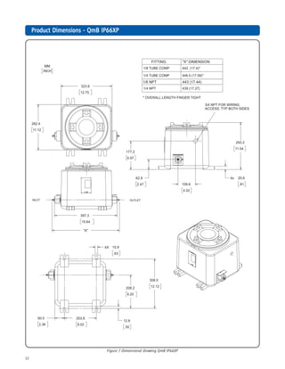
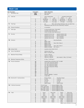
Process Fitting Options:Process Fitting Options:Process Fitting Options:Process Fitting Options:Process Fitting Options: 1/16”, 1/8”, 1/4” or 6mm tube compression, VCR, VCO or NPT(F), 3.2 mm UPG,
Downport ANSI/ISA 76.00.02 (See Model Code)
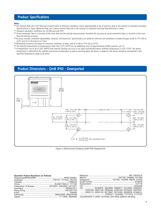
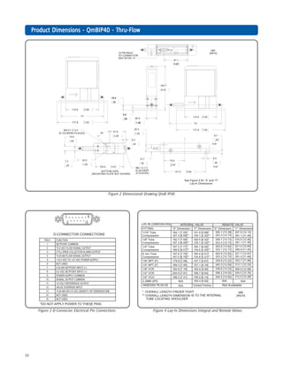
Electrical Connections:Electrical Connections:Electrical Connections:Electrical Connections:Electrical Connections: IP40: 15 pin D-Type connector (See Figure 3).
IP66: Unpluggable Terminal Block 28-16 Awg.
IP66XP: 3/4” NPT wiring access to IP40 device with 15 pin D-Type connector.
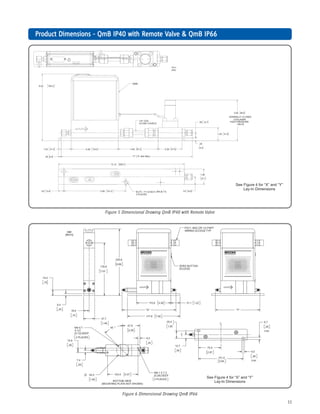
Dimensions:Dimensions:Dimensions:Dimensions:Dimensions: (See Figures 1 through 7)](https://image.slidesharecdn.com/mass-flow-controller-data-sheet-quantim-171018100425/85/Mass-Flow-Controller-Quantim-Series-7-320.jpg)

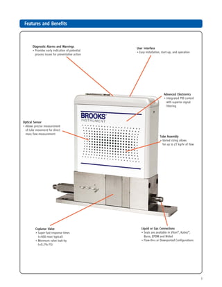
The Brooks Instrument's Quantim® series is the smallest and lowest flow coriolis mass flow meter and controller, designed for precise measurement and control of low flows from 0.001 to over 27 kg/hr. It features an integrated sensor and optional control valve, allowing for simultaneous measurement of mass or volumetric flow and fluid density or temperature, suitable for various applications in critical processes. The device is available in multiple configurations, ensuring adaptability for different environments and process needs.


