![10/10/2017
7
13
Meet- en Regeltechniek
Classification-Definition Safety Valves-AD2000-A2
Performance / Opening Characteristics
Opening Characteristics
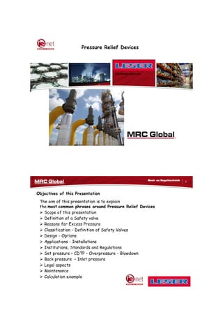
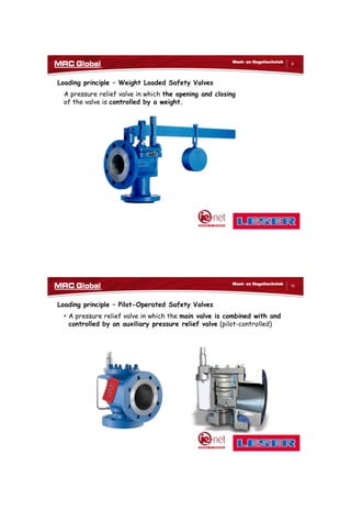
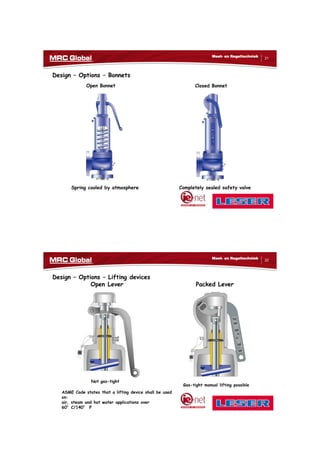
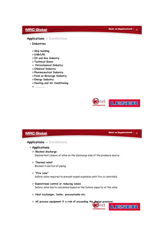
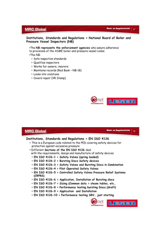
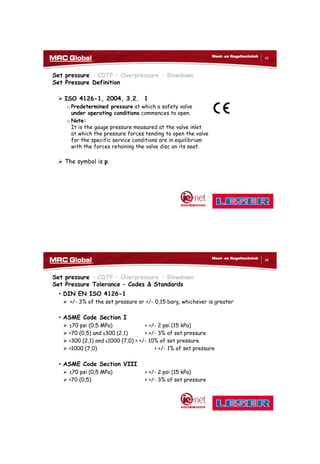
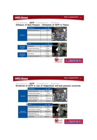
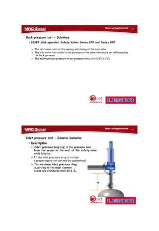
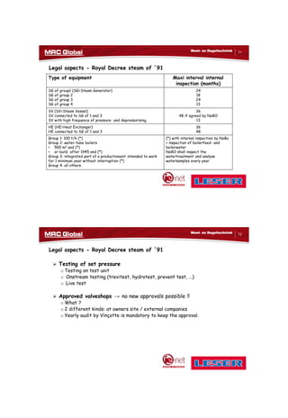
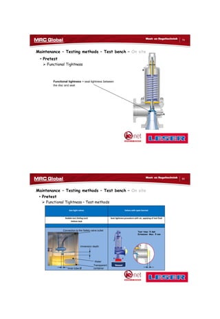
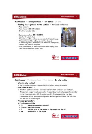
o Normal Safety Valve Pursuant to AD 2000 Information Sheet A2
A spring loaded pressure relief valve actuated by the static pressure upstream of
the valve. The valve opens in proportion to the pressure increase over the opening
pressure. Used primarily with liquid service (non-compressible).
100
80
60
40
20
0
Lift [%]
pc
p = set pressure pc = opening pressure
pp = popping pressure ps = closing pressure
90 100 110
ps
p
Pressure [%]
pp
14
Meet- en Regeltechniek
Classification-Definition Safety Valves-AD2000-A2
Performance / Opening Characteristics
Opening Characteristics
o Normal Safety Valve Pursuant to AD 2000 Information Sheet A2
A spring-loaded normal safety valve opening proportionately or suddenly within a
pressure increase of 10%.
Used with all media: steam, vapour, gas and liquids.
100
80
60
40
20
0
Lift [%]
pc
p = set pressure pc = opening pressure
pp = popping pressure ps = closing pressure
ps
p
Pressure [%]
pp
80 90 100 105 110 120
Standard 10% - Pop-Acting](https://image.slidesharecdn.com/ienetpresentationmrcglobalmdj-171018103727/85/Pressure-Relief-Devices-7-320.jpg)
![10/10/2017
8
15
Meet- en Regeltechniek
Classification-Definition Safety Valves-AD2000-A2
Performance / Opening Characteristics
Opening Characteristics
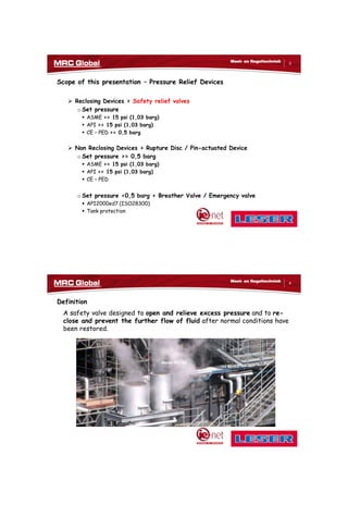
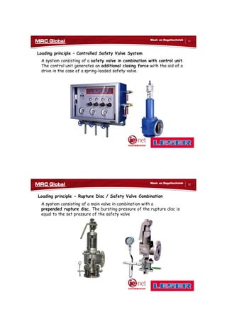
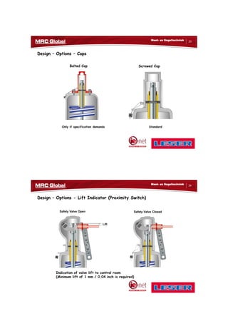
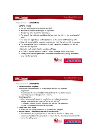
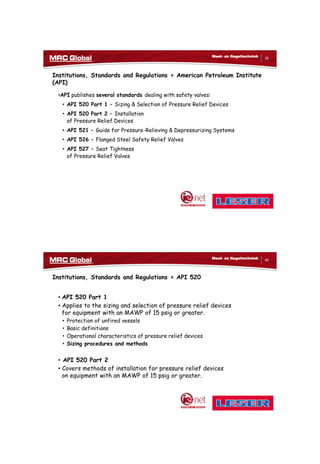
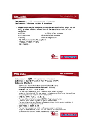
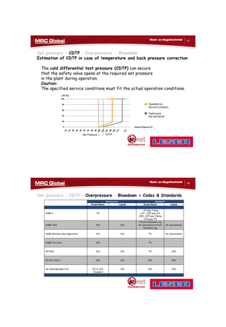
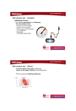
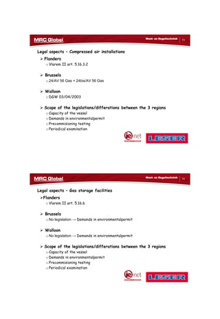
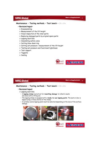
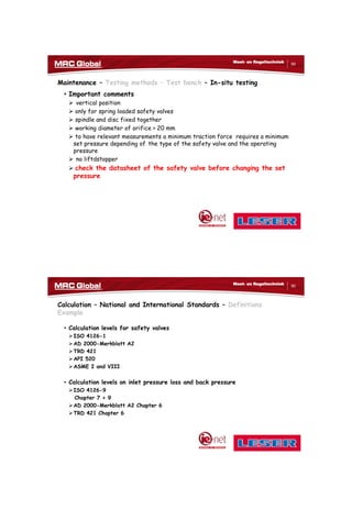
o Full-lift Safety Valve Pursuant to AD 2000 Information Sheet A2
A spring-loaded full-lift safety valve opening suddenly within a pressure increase of
5%. Primarily used for gas, steam and vapour
100
80
60
40
20
0
Lift [%]
pc
p = set pressure pc = opening pressure
pp = popping pressure ps = closing pressure
ps
p
Pressure [%]
pp
80 90 100 105 110 120
Sudden opening within 5%
16
Meet- en Regeltechniek
Classification-Definition Safety Valves-ASME PTC 25-2014
Performance / Opening Characteristics
Relief valve
o A pressure relief valve characterized by gradual opening that is generally
proportional to the increase in pressure. It is normally used for incompressible
fluids.
Safety relief valve
o A pressure relief valve characterized by rapid opening or by gradual opening that
is generally proportional to the increase in pressure. It can be used for
compressible or incompressible fluids.
Safety valve
o A pressure relief valve characterized by rapid opening and normally used to
relieve compressible fluids.
Prssure [%]](https://image.slidesharecdn.com/ienetpresentationmrcglobalmdj-171018103727/85/Pressure-Relief-Devices-8-320.jpg)
![10/10/2017
26
51
Meet- en Regeltechniek
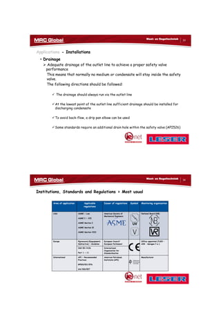
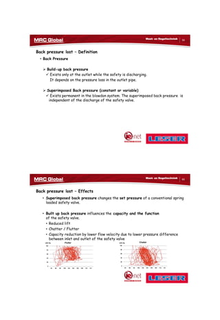
Set pressure – CDTP – Overpressure - Blowdown
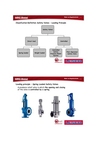
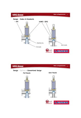
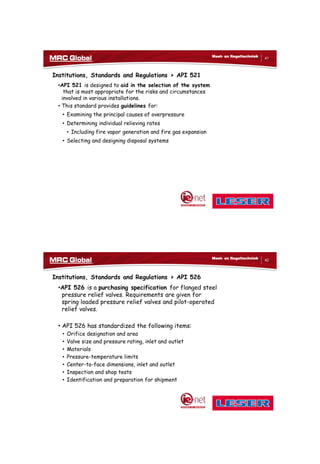
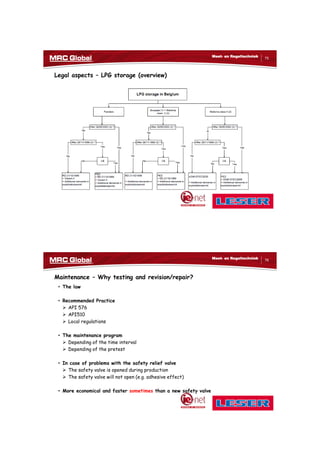
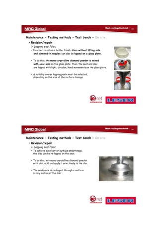
Influence of Temperature - Estimation of CDTP in Theory
Set Pressure 10 bar
Operation
Required spring force 2.000 N
Medium temperature 300 °C
Spring rate at 300°C
medium temperature
95 N/mm
Spring preloaded 21 mm
CDTP (acc. LDeS 1001.69
+ 0,5 bar temperature correction)
10,5 bar
Test bench
Spring preloaded 21 mm
Spring rate at 20°C
temperature at test lab
100 N/mm
Spring force 2.100 N
52
Meet- en Regeltechniek
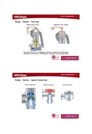
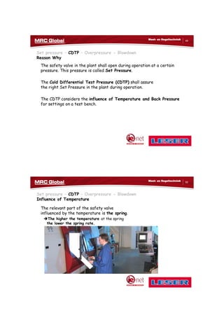
Set pressure – CDTP – Overpressure - Blowdown
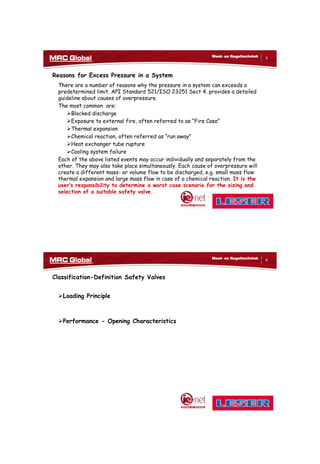
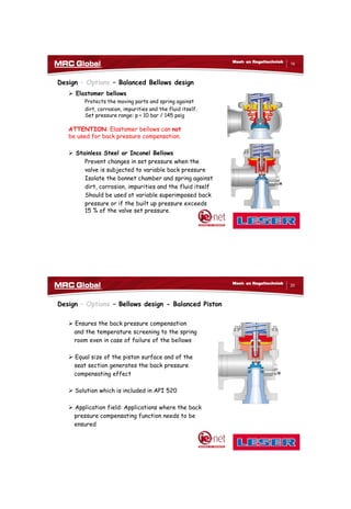
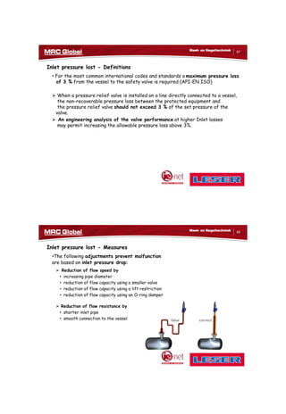
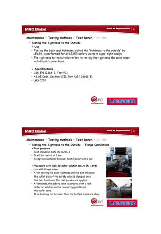
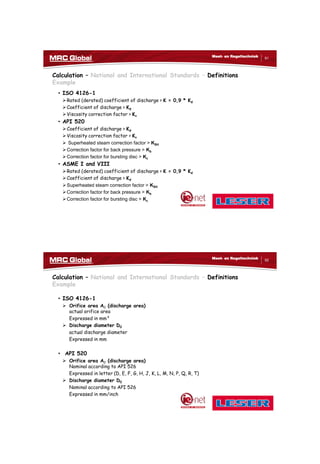
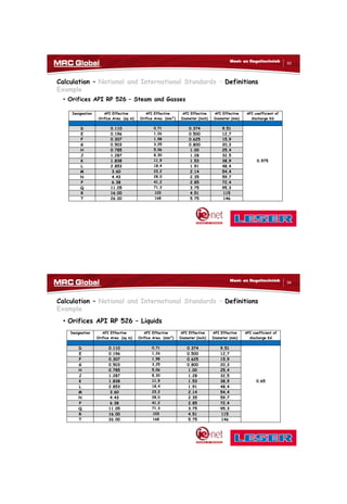
Influence of Temperature - Estimation of CDTP in Practice
-508 -308 -108 92 292 492 692 892
0,96
0,98
1
1,02
1,04
1,06
1,08
1,1
1,12
-300 -200 -100 0 100 200 300 400 500
Temperature T [°F]
CorrectionfactorkT
Temperature T [°C]
Conventional design with closed bonnet
upward set pressure (+3%) of allowable tolerances ( 3%)
according to EN ISO 4126-1 2003-09
downward set pressure (-3%) of allowable tolarance
( 3) according to EN ISO 4126-1 2003-09
Approved correction curve by
German TÜV Nord](https://image.slidesharecdn.com/ienetpresentationmrcglobalmdj-171018103727/85/Pressure-Relief-Devices-26-320.jpg)


This presentation covers pressure relief devices, specifically safety valves, their definitions, types, design options, classifications, legal aspects, and maintenance. It outlines the causes of excess pressure, various loading principles, and applicable regulations from organizations like ASME, API, and ISO. The document also addresses installation applications, general issues, and best practices to ensure safety and compliance.


