Download to read offline
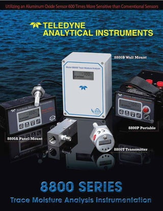
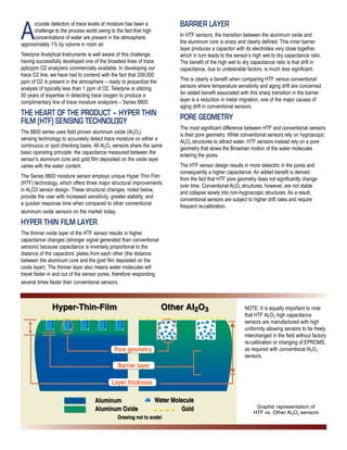


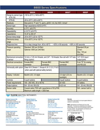

Teledyne Analytical Instruments has developed the series 8800 of trace moisture analyzers using hyper thin film (HTF) aluminum oxide (Al2O3) sensing technology, which provides increased sensitivity, stability, and faster response time compared to conventional sensors. The unique design of HTF sensors allows for greater accuracy in detecting trace moisture levels while reducing the need for frequent recalibration. This document outlines the technical specifications, benefits, and operational principles of the 8800 series systems, which are suitable for various applications requiring precise moisture detection.