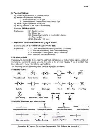
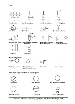
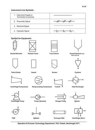
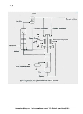
01.01
Operation & Process Technology Department, TICI, Polash, Narshingdi-1611
PROCESS SYMBOL & PROCESS DIAGRAM
MD. MOHIUDDIN
Chemist,OPTD
Symbol:
Symbol is a mark or character of a specific subject or object. Symbols of pipelines, fittings, vessels,
machines, instruments, etc. are used to make diagrams of industrial processes and plants.
A set of symbols has been adopted by many international organizations. Such as:
ISA - The Instrument Society of America
BSI - The British Standard Institution
JIS - Japanese Industrial Standard
ISO - International Standard Organization
ANSI - American National Standard Institute
Diagram:
Diagram represents the total or partial course of the process. Basic and important diagrams to
process concern:
1. Block diagram
2. Flow diagram
3. Process diagram
4. Piping & Instrumentation (P&I) diagram
Block diagram:
• A block diagram is the simplest form of presentation.
• Each block can represent a single piece of equipment or a complete stage in the process.
• They are useful for showing simple processes.
• With complex processes, their use is limited to show the overall process (which is broken
down into its principal stages). Each block can represent equipment (e.g., reactor,
separators, distillation columns, etc.) with several other processing units.
• The stream flow-rates and compositions can be shown on the diagram adjacent to the
streamlines.
• The blocks can be of any shape, but it is usually convenient to use a mixture of squares
and circles.
Flow diagram:
This is a diagram in which all the unit operations necessary for the process are represented with
the help of simple figures of machine and/or equipment instead of blocks.
Process Flow Diagram (PFD) or Process Flow Sheets:
• The flow sheet is the key document in a process design.
• It shows the arrangements of the equipment selected to carry out the process, the stream
connections, stream flow-rates and compositions as well as the operating conditions.
• It is a description of the nature of the process.
Information to be included:
The amount of information shown on a flow sheet depends on the custom and practice of the
particular design office.
Essential information:
• Stream composition
• Total stream flow-rate (kg/h)
• Stream temperature (e.g., degree Celsius)
• Nominal operating pressure (the required operating pressure, e.g., bar, psi, etc.)
01.02
Operation & Process Technology Department, TICI, Polash, Narshingdi-1611
Optional information:
• Molar percentage composition
• Physical property, mean values for the stream, e.g.,
• density
• viscosity
• Stream name in brief (one or two word), description of the nature of the stream, for
example, “ACETONE COLUMN BOTTOM”.
• Stream enthalpy, etc.
Piping & Instrumentation Diagrams (P&I):
• The Piping & Instrumentation Diagram shows the engineering details of the equipment,
instruments, piping, valves and fittings as well as their arrangements.
• It is often called the Engineering Flow Sheet or Engineering Line Diagram.
P&I Diagram should include:
• All process equipment identified by an equipment number. The equipment should be
drawn roughly in proportion with their relative size. All height differences are shown on
the diagram.
• All pipes identified by a line number. The pipe size and material of construction should
be shown.
• All valves - control and block valves, etc. - are indicated with an identification number.
The type and size should be shown clearly. The type may be shown by the symbol used
for the valve or includes in the code used for the valve number.
• Ancillary fittings that are part of the piping system such as inline sight-glasses, strainers
and steam traps, etc. should indicate with an identification number.
• Pumps are identified with a suitable code number.
• All control loops and instruments should denote with an identification number.
• For simple processes, the utility (service) lines can be shown on the P&I diagram.
• For complex processes, separate diagrams should be used to show the service lines,
so that the information can be shown clearly. The service connections to each unit
should, however, be shown on the P&I diagram.
• The P&I diagram will resemble the process flow-sheet, but the process information is
not shown. The same Equipment Identification Numbers should be used on all
diagrams.
Explanation of different Identification Codes/Numbers:
1. Equipment Coding (Equipment Identification Number):
a) One capital letter - Function of the equipment.
b) 4-digits - i) 1st
two digits indicate Section Number
ii) 2nd
two digits indicate Sequence no. of equipment (equipment no.).
Alphabetical Code Letters:
A - Stack, Torch, Sound Absorber
B - Solids Handling and Conveyance Equipment
C - Columns (Absorber, Scrubber etc.)
D - Dryers
E- Electric motors
F - Furnace
H -Heat exchanger
P –Pump
Example: D0102
Explanation: D - Dryer
01 - Section number
02 - Equipment (dryer) number.
01.03
Operation & Process Technology Department, TICI, Polash, Narshingdi-1611
2. Pipeline Coding:
a) 1st
two digits - Number of process section
b) Next 4/5 Alphabets/Characters
i) 1st
two characters -Fluid type
ii) other characters -Material of construction of pipe
c) Next 2 digits - Sequence no. of pipe
d) Finally diameter of the pipe (D = diameter)
Example: 02SLBA10D100
Explanation: 02 - Section number
SL - Steam line
BA - Brass alloy (material of construction of pipe)
10 - Pipe number
D100 - Diameter (100 mm)
3. Instrument Identification Number (Tag Number):
Example: LIC-326 (Level Indicating Controller-326)
Explanation: L = Level (Measured or Initiating variable) (1st
Letter)
I = Indicate (Succeeding letter, Passive function)
C = Control (Succeeding letter, Output function)
326= Section & Sequence number
Process symbols
Process symbols may be defined as the graphical, alphabetical or mathematical representation of
instruments, equipment, valves, vessels, lines etc. of the process industry. A set of symbols has
been adopted by many international organizations.
The followings are the commonly used symbols in process industries:
Symbol for Valves:
Valve (General) Hand Control Globe Ball Angle
Butterfly Ball Diaphragm Check Three Way Four Way
Quick Acting Pneumatic Control Valve
Symbol for Pipe lines, and other devices:
Flanged and Bolted Connection Open Spectacle Blind Closed Spectacle Blind Hose connection
or
01.04
Operation & Process Technology Department, TICI, Polash, Narshingdi-1611
Insulated Line Elbow 90 Tee Vent
1.4 mm 0.7 mm 0.35 mm
Flow Direction Main Process Line Other Process Line Utility Line
Pipe Filter Orifice Plate Steam Trap Open Hopper (Drain)
Magnetic Flow Meter Float Operated Flow Meter, Gauge Glass Integrally Gauge Glass
Rotameter Mounted on Tank Externally Mounted
Level Gauge Sight Glass
Actuator Symbols:
Diaphragm Actuator Rotary Motor (Shown Solenoid Hand Actuator
Typically with electric signal)
Instrument representation on flow diagram:
Transmitter Field Mounted Inst. Mounted on Main Panel
Behind the Panel Local Panel Pressure Regulator
L
u
i
01.05
Operation & Process Technology Department, TICI, Polash, Narshingdi-1611
Instrument Line Symbols:
1. Instrument Supply or
Connection to process
2. Pneumatic Signal
3. Electrical Signal
4. Hydraulic Signal
Symbol for Equipment:
Bucket Elevator Packed Tower Tray Column Vessel General (Open
above Ground)
Tank (Close) Vessel Screen Cyclone
Centrifugal Compressor Reciprocating Compressor Turbine Heat Exchanger
Centrifugal Pump Pump (General) Plunger Pump Ejector
FAN Agitator Conveyer Belt Centrifuge (Gen.)
01.06
Operation & Process Technology Department, TICI, Polash, Narshingdi-1611

1T-Process-Symbols-And-Diagram.pdf

  • 1.
    01.01 Operation & ProcessTechnology Department, TICI, Polash, Narshingdi-1611 PROCESS SYMBOL & PROCESS DIAGRAM MD. MOHIUDDIN Chemist,OPTD Symbol: Symbol is a mark or character of a specific subject or object. Symbols of pipelines, fittings, vessels, machines, instruments, etc. are used to make diagrams of industrial processes and plants. A set of symbols has been adopted by many international organizations. Such as: ISA - The Instrument Society of America BSI - The British Standard Institution JIS - Japanese Industrial Standard ISO - International Standard Organization ANSI - American National Standard Institute Diagram: Diagram represents the total or partial course of the process. Basic and important diagrams to process concern: 1. Block diagram 2. Flow diagram 3. Process diagram 4. Piping & Instrumentation (P&I) diagram Block diagram: • A block diagram is the simplest form of presentation. • Each block can represent a single piece of equipment or a complete stage in the process. • They are useful for showing simple processes. • With complex processes, their use is limited to show the overall process (which is broken down into its principal stages). Each block can represent equipment (e.g., reactor, separators, distillation columns, etc.) with several other processing units. • The stream flow-rates and compositions can be shown on the diagram adjacent to the streamlines. • The blocks can be of any shape, but it is usually convenient to use a mixture of squares and circles. Flow diagram: This is a diagram in which all the unit operations necessary for the process are represented with the help of simple figures of machine and/or equipment instead of blocks. Process Flow Diagram (PFD) or Process Flow Sheets: • The flow sheet is the key document in a process design. • It shows the arrangements of the equipment selected to carry out the process, the stream connections, stream flow-rates and compositions as well as the operating conditions. • It is a description of the nature of the process. Information to be included: The amount of information shown on a flow sheet depends on the custom and practice of the particular design office. Essential information: • Stream composition • Total stream flow-rate (kg/h) • Stream temperature (e.g., degree Celsius) • Nominal operating pressure (the required operating pressure, e.g., bar, psi, etc.)
  • 2.
    01.02 Operation & ProcessTechnology Department, TICI, Polash, Narshingdi-1611 Optional information: • Molar percentage composition • Physical property, mean values for the stream, e.g., • density • viscosity • Stream name in brief (one or two word), description of the nature of the stream, for example, “ACETONE COLUMN BOTTOM”. • Stream enthalpy, etc. Piping & Instrumentation Diagrams (P&I): • The Piping & Instrumentation Diagram shows the engineering details of the equipment, instruments, piping, valves and fittings as well as their arrangements. • It is often called the Engineering Flow Sheet or Engineering Line Diagram. P&I Diagram should include: • All process equipment identified by an equipment number. The equipment should be drawn roughly in proportion with their relative size. All height differences are shown on the diagram. • All pipes identified by a line number. The pipe size and material of construction should be shown. • All valves - control and block valves, etc. - are indicated with an identification number. The type and size should be shown clearly. The type may be shown by the symbol used for the valve or includes in the code used for the valve number. • Ancillary fittings that are part of the piping system such as inline sight-glasses, strainers and steam traps, etc. should indicate with an identification number. • Pumps are identified with a suitable code number. • All control loops and instruments should denote with an identification number. • For simple processes, the utility (service) lines can be shown on the P&I diagram. • For complex processes, separate diagrams should be used to show the service lines, so that the information can be shown clearly. The service connections to each unit should, however, be shown on the P&I diagram. • The P&I diagram will resemble the process flow-sheet, but the process information is not shown. The same Equipment Identification Numbers should be used on all diagrams. Explanation of different Identification Codes/Numbers: 1. Equipment Coding (Equipment Identification Number): a) One capital letter - Function of the equipment. b) 4-digits - i) 1st two digits indicate Section Number ii) 2nd two digits indicate Sequence no. of equipment (equipment no.). Alphabetical Code Letters: A - Stack, Torch, Sound Absorber B - Solids Handling and Conveyance Equipment C - Columns (Absorber, Scrubber etc.) D - Dryers E- Electric motors F - Furnace H -Heat exchanger P –Pump Example: D0102 Explanation: D - Dryer 01 - Section number 02 - Equipment (dryer) number.
  • 3.
    01.03 Operation & ProcessTechnology Department, TICI, Polash, Narshingdi-1611 2. Pipeline Coding: a) 1st two digits - Number of process section b) Next 4/5 Alphabets/Characters i) 1st two characters -Fluid type ii) other characters -Material of construction of pipe c) Next 2 digits - Sequence no. of pipe d) Finally diameter of the pipe (D = diameter) Example: 02SLBA10D100 Explanation: 02 - Section number SL - Steam line BA - Brass alloy (material of construction of pipe) 10 - Pipe number D100 - Diameter (100 mm) 3. Instrument Identification Number (Tag Number): Example: LIC-326 (Level Indicating Controller-326) Explanation: L = Level (Measured or Initiating variable) (1st Letter) I = Indicate (Succeeding letter, Passive function) C = Control (Succeeding letter, Output function) 326= Section & Sequence number Process symbols Process symbols may be defined as the graphical, alphabetical or mathematical representation of instruments, equipment, valves, vessels, lines etc. of the process industry. A set of symbols has been adopted by many international organizations. The followings are the commonly used symbols in process industries: Symbol for Valves: Valve (General) Hand Control Globe Ball Angle Butterfly Ball Diaphragm Check Three Way Four Way Quick Acting Pneumatic Control Valve Symbol for Pipe lines, and other devices: Flanged and Bolted Connection Open Spectacle Blind Closed Spectacle Blind Hose connection or
  • 4.
    01.04 Operation & ProcessTechnology Department, TICI, Polash, Narshingdi-1611 Insulated Line Elbow 90 Tee Vent 1.4 mm 0.7 mm 0.35 mm Flow Direction Main Process Line Other Process Line Utility Line Pipe Filter Orifice Plate Steam Trap Open Hopper (Drain) Magnetic Flow Meter Float Operated Flow Meter, Gauge Glass Integrally Gauge Glass Rotameter Mounted on Tank Externally Mounted Level Gauge Sight Glass Actuator Symbols: Diaphragm Actuator Rotary Motor (Shown Solenoid Hand Actuator Typically with electric signal) Instrument representation on flow diagram: Transmitter Field Mounted Inst. Mounted on Main Panel Behind the Panel Local Panel Pressure Regulator L u i
  • 5.
    01.05 Operation & ProcessTechnology Department, TICI, Polash, Narshingdi-1611 Instrument Line Symbols: 1. Instrument Supply or Connection to process 2. Pneumatic Signal 3. Electrical Signal 4. Hydraulic Signal Symbol for Equipment: Bucket Elevator Packed Tower Tray Column Vessel General (Open above Ground) Tank (Close) Vessel Screen Cyclone Centrifugal Compressor Reciprocating Compressor Turbine Heat Exchanger Centrifugal Pump Pump (General) Plunger Pump Ejector FAN Agitator Conveyer Belt Centrifuge (Gen.)
  • 6.
    01.06 Operation & ProcessTechnology Department, TICI, Polash, Narshingdi-1611