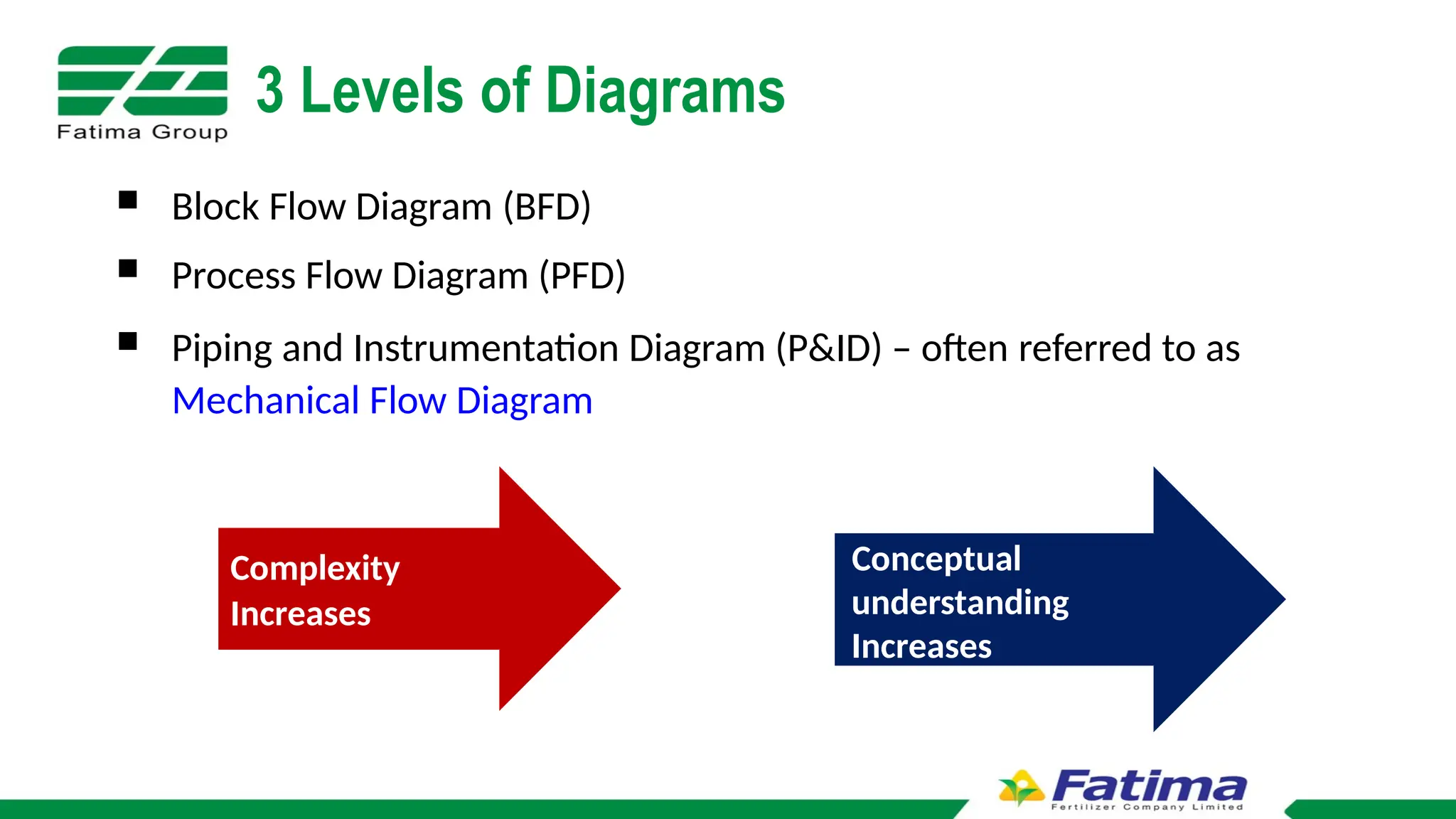
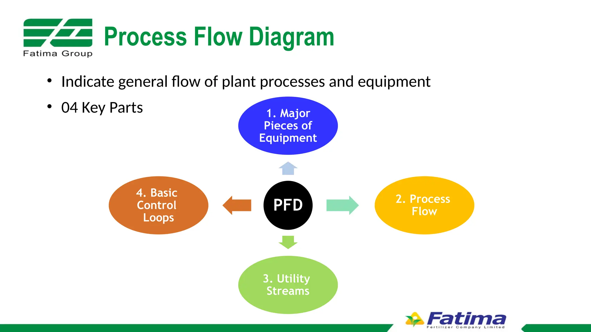
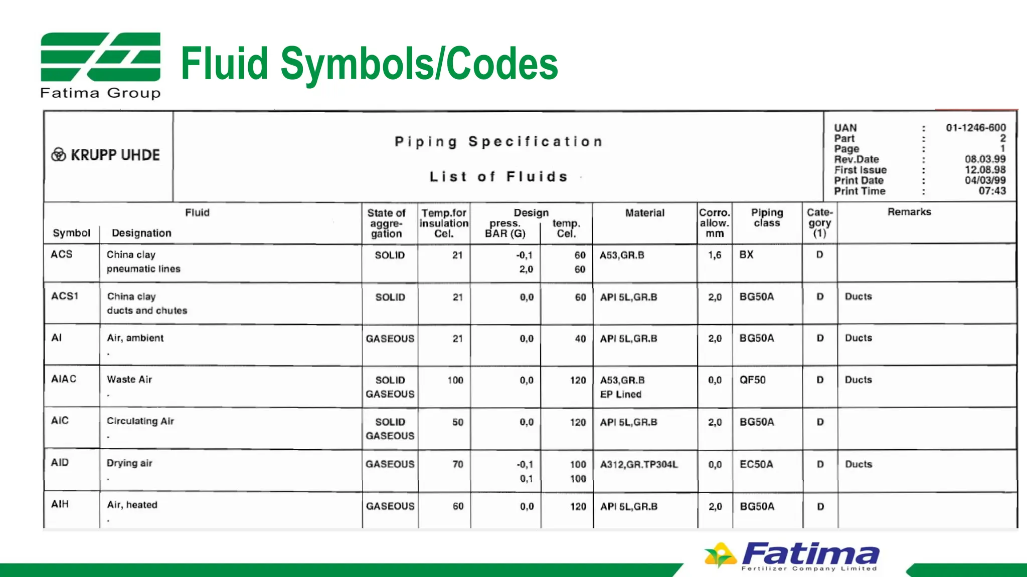
BASIC UNDERSTANDING OF
BFD, PFD AND P&IDs
1
By:
Azmul Haq
(Process Engineering)
Contents
1. Block Flow Diagram
2. Process Flow Diagram
o Equipment Symbols, Streams on PFD
o Process Unit Tagging & Numbering
3. Piping & Instrumentation Diagram
o Temperature Control System
o Developing P&ID
o Tag Numbers & Description for Instruments
o ISA Identification Letters
o Location of Instruments
o Piping connections & Symbols
o Line Number Format
o Piping Specifications
o Fluid Symbols or Codes
2
3 Levels of Diagrams
 Block Flow Diagram (BFD)
 Process Flow Diagram (PFD)
 Piping and Instrumentation Diagram (P&ID) – often referred to as
Mechanical Flow Diagram
Complexity
Increases
Conceptual
understanding
Increases
BLOCK FLOW DIAGRAM
CAN Plant BFD
Ammonium
Nitrate Solution
Unit
Evaporation Concentration Granulation
Drying Sieving
Product
Conditioning
Bulk Storage /
Bagging
Ammonia Nitric Acid Steam Vent Gases Air/Steam Vent Gases
Lime Grinding
Unit
Lime Stone
Dried
Lime
from NP
Plant
Vent Gases
Hot Air Vent Gases
Oil/Amine
Air
PROCESS FLOW DIAGRAM
Process Flow Diagram
• Indicate general flow of plant processes and equipment
• 04 Key Parts
PFD
1. Major
Pieces of
Equipment
2. Process
Flow
3. Utility
Streams
4. Basic
Control
Loops
Process Flow Diagram
PFD includes following information;
• Flow rate
• Composition
• Operating Conditions e.g. P , T, etc.
• Heat Duty added or removed
• Utility Streams e.g. Steam, Cooling Water, Chilled Water etc.
• Major Equipment Symbols, names and identification
• Any other specific information which is useful in understanding the
process. For example, symbolic presentation of a hazard, safety
precautions, sequence of flow, etc.
Equipment Symbols
Equipment Symbols
Process Unit Tagging and Numbering
General Format X-YYY-A/B
X is equipment tag
C/CT – Compressor/Turbine
E/H - Heat Exchanger
P - Pump
R - Reactor
T - Tower
TK - Storage Tank
D - Vessel
B- Blower
FIL- Filter
YYY – Equipment Number
A/B - identifies parallel units or
backup units
PROCESS AND
INSTRUMENTATION DIAGRAM
P&ID
• Detailed graphical representation of a process including the hardware and
software (i.e. piping, equipment, and instrumentation).
• A P&ID shows all piping, including the “physical sequence of branches, reducers,
valves, equipment, instrumentation and control interlocks.
• P&IDs play a key role in maintaining and modifying the process they describe,
because it is important to demonstrate the physical sequence of equipment and
systems, including how these systems connect.
Key Features of P&ID
The following list outlines the items that typically are found in a P&ID:
• Instrumentation and designations
• Mechanical equipment with names and numbers
• All valves and their identifications
• Process piping, sizes, and identification
• Flow directions
• Control inputs and outputs, interlocks
• Computer control system
• Identification of components and subsystems delivered by the process
Transmitter
Controller
Orifice
(Flow Sensor)
Set
point
Flui
d
Flui
d
Basic Flow Control Loop
Temperature Control System
P&ID Building
Tag Description
Tag Number & Description
ISA S5.1 Identification Letters
• FC Flow Controller PT Pressure Transmitter
• FE Flow Element PTD Pressure Transducer
• FI Flow Indicator FT Flow Transmitter
• LC Level Controller FS Flow Switch
• LG Level Gauge LR Level Recorder
• FIC Flow Indicating Controller FCV Flow Control Valve
• LT Level Transmitter FRC Flow Recording Controller
• LS Level Switch LIC Level Indicating Controller
• PC Pressure Controller LCV Level Control Valve
• PG Pressure Gauge LRC Level Recording Controller
• PI Pressure Indicator PR Pressure Recorder
ISA S5.1 Identification Letters
• TE Temperature Element PS Pressure Switch
• TI Temperature Indicator PIC Pressure Indicating Controller
• TR Temperature Recorder PCV Pressure Control Valve
• TS Temperature Switch PRC Pressure Recording Controller
• TC Temperature Controller PDI Pressure Differential Indicator
• TT Temperature Transmitter PDR Pressure Differential Recorder
• PDS Pressure Differential Switch PDT Pressure Differential Transmitter
Instrument Location
Instruments that are field mounted.
Instruments that are mounted on process plant (i.e sensor that
mounted on pipeline or process equipments.
Field
mounted
on pipeline
Instrument Location
Instruments that are board mounted
Instruments that are mounted on control board.
Instrument Location
Instruments that are board mounted (invisible).
Instruments that are mounted behind a control panel board.
Instrument Location
Instrument Connections
Piping Symbols & Connections
PIPING SPECIFICATIONS
Pipeline Number Format
Piping Specifications
Fluid Symbols/Codes
• American National Standards Institute / International
Society of Automation ISA S5-1
• International Standards Organization 14617-6
• Software: MS Visio, Smart P&ID, AutoCAD P&ID, etc
PFD and P&ID Standards
Thanks

Block flow diagrams, Process flow diagrams, and Process and Instrumentation Diagrams

  • 1.
    BASIC UNDERSTANDING OF BFD,PFD AND P&IDs 1 By: Azmul Haq (Process Engineering)
  • 2.
    Contents 1. Block FlowDiagram 2. Process Flow Diagram o Equipment Symbols, Streams on PFD o Process Unit Tagging & Numbering 3. Piping & Instrumentation Diagram o Temperature Control System o Developing P&ID o Tag Numbers & Description for Instruments o ISA Identification Letters o Location of Instruments o Piping connections & Symbols o Line Number Format o Piping Specifications o Fluid Symbols or Codes 2
  • 3.
    3 Levels ofDiagrams  Block Flow Diagram (BFD)  Process Flow Diagram (PFD)  Piping and Instrumentation Diagram (P&ID) – often referred to as Mechanical Flow Diagram Complexity Increases Conceptual understanding Increases
  • 4.
  • 5.
    CAN Plant BFD Ammonium NitrateSolution Unit Evaporation Concentration Granulation Drying Sieving Product Conditioning Bulk Storage / Bagging Ammonia Nitric Acid Steam Vent Gases Air/Steam Vent Gases Lime Grinding Unit Lime Stone Dried Lime from NP Plant Vent Gases Hot Air Vent Gases Oil/Amine Air
  • 6.
  • 7.
    Process Flow Diagram •Indicate general flow of plant processes and equipment • 04 Key Parts PFD 1. Major Pieces of Equipment 2. Process Flow 3. Utility Streams 4. Basic Control Loops
  • 8.
    Process Flow Diagram PFDincludes following information; • Flow rate • Composition • Operating Conditions e.g. P , T, etc. • Heat Duty added or removed • Utility Streams e.g. Steam, Cooling Water, Chilled Water etc. • Major Equipment Symbols, names and identification • Any other specific information which is useful in understanding the process. For example, symbolic presentation of a hazard, safety precautions, sequence of flow, etc.
  • 9.
  • 10.
  • 11.
    Process Unit Taggingand Numbering General Format X-YYY-A/B X is equipment tag C/CT – Compressor/Turbine E/H - Heat Exchanger P - Pump R - Reactor T - Tower TK - Storage Tank D - Vessel B- Blower FIL- Filter YYY – Equipment Number A/B - identifies parallel units or backup units
  • 12.
  • 13.
    P&ID • Detailed graphicalrepresentation of a process including the hardware and software (i.e. piping, equipment, and instrumentation). • A P&ID shows all piping, including the “physical sequence of branches, reducers, valves, equipment, instrumentation and control interlocks. • P&IDs play a key role in maintaining and modifying the process they describe, because it is important to demonstrate the physical sequence of equipment and systems, including how these systems connect.
  • 14.
    Key Features ofP&ID The following list outlines the items that typically are found in a P&ID: • Instrumentation and designations • Mechanical equipment with names and numbers • All valves and their identifications • Process piping, sizes, and identification • Flow directions • Control inputs and outputs, interlocks • Computer control system • Identification of components and subsystems delivered by the process
  • 15.
  • 16.
  • 17.
  • 18.
  • 19.
    Tag Number &Description
  • 20.
    ISA S5.1 IdentificationLetters • FC Flow Controller PT Pressure Transmitter • FE Flow Element PTD Pressure Transducer • FI Flow Indicator FT Flow Transmitter • LC Level Controller FS Flow Switch • LG Level Gauge LR Level Recorder • FIC Flow Indicating Controller FCV Flow Control Valve • LT Level Transmitter FRC Flow Recording Controller • LS Level Switch LIC Level Indicating Controller • PC Pressure Controller LCV Level Control Valve • PG Pressure Gauge LRC Level Recording Controller • PI Pressure Indicator PR Pressure Recorder
  • 21.
    ISA S5.1 IdentificationLetters • TE Temperature Element PS Pressure Switch • TI Temperature Indicator PIC Pressure Indicating Controller • TR Temperature Recorder PCV Pressure Control Valve • TS Temperature Switch PRC Pressure Recording Controller • TC Temperature Controller PDI Pressure Differential Indicator • TT Temperature Transmitter PDR Pressure Differential Recorder • PDS Pressure Differential Switch PDT Pressure Differential Transmitter
  • 22.
  • 23.
    Instruments that arefield mounted. Instruments that are mounted on process plant (i.e sensor that mounted on pipeline or process equipments. Field mounted on pipeline Instrument Location
  • 24.
    Instruments that areboard mounted Instruments that are mounted on control board. Instrument Location
  • 25.
    Instruments that areboard mounted (invisible). Instruments that are mounted behind a control panel board. Instrument Location
  • 26.
  • 27.
    Piping Symbols &Connections
  • 28.
  • 29.
  • 30.
  • 31.
  • 32.
    • American NationalStandards Institute / International Society of Automation ISA S5-1 • International Standards Organization 14617-6 • Software: MS Visio, Smart P&ID, AutoCAD P&ID, etc PFD and P&ID Standards
  • 33.