The document is a project report on 'SUAS Network Suite' submitted to Symbiosis University of Applied Sciences, detailing the implementation of a complex intra-networking system utilizing protocols such as DHCP, DNS, HTTP, FTP, and SMTP. It outlines the project’s objectives, methodologies including an iterative software development model, tools used, and project management plans. The project also emphasizes the configuration of various network services and provides acknowledgments to contributors and guides.


![CHAPTER 5 – Network Addressing
1. IPv4 Addressing
1.1 Introduction
Internet Protocol version 4 (IPv4) is the fourth version of the Internet Protocol (IP). It is one of the
core protocols of standards-based internetworking methods in the Internet, and was the first
version deployed for production in the ARPANET in 1983. It still routes most Internet traffic today,
despite the ongoing deployment of a successor protocol, IPv6. IPv4 is described in IETF publication
RFC 791 (September 1981), replacing an earlier definition (RFC 760, January 1980).
IPv4 is a connectionless protocol for use on packet-switched networks. It operates on a best effort
delivery model, in that it does not guarantee delivery, nor does it assure proper sequencing or
avoidance of duplicate delivery. These aspects, including data integrity, are addressed by an upper
layer transport protocol, such as the Transmission Control Protocol (TCP).
1.2 Addressing of Ipv4:
IPv4 uses 32-bit addresses which limits the address space to 4294967296(232
) addresses. IPv4
reserves special address blocks for private networks (~18 million addresses) and multicast
addresses (~270 million addresses).
1.3 IPv4 is divided into five classes:
1.4 Allocation of ipv4 Address:
In the original design of IPv4, an IP address was divided into two parts: the network identifier was the
most significant (highest order) octet of the address, and the host identifier was the rest of the address.
The latter was also called the rest field. This structure permitted a maximum of 256 network identifiers,
which was quickly found to be inadequate.
To overcome this limit, the most-significant address octet was redefined in 1981 to create network
classes, in a system which later became known as classful networking. The revised system defined five
classes. Classes A, B, and C had different bit lengths for network identification. The rest of the address
was used as previously to identify a host within a network, which meant that each network class had a
different capacity for addressing hosts. Class D was defined for multicast addressing and Class E was
reserved for future applications.
Starting around 1985, methods were devised to subdivide IP networks. One method that has proved
flexible is the use of the variable-length subnet mask (VLSM).[2][3]
Based on the IETF standard RFC 1517](https://image.slidesharecdn.com/finalreportcn-180224162151/75/Private-Network-Project-for-Colleges-33-2048.jpg)
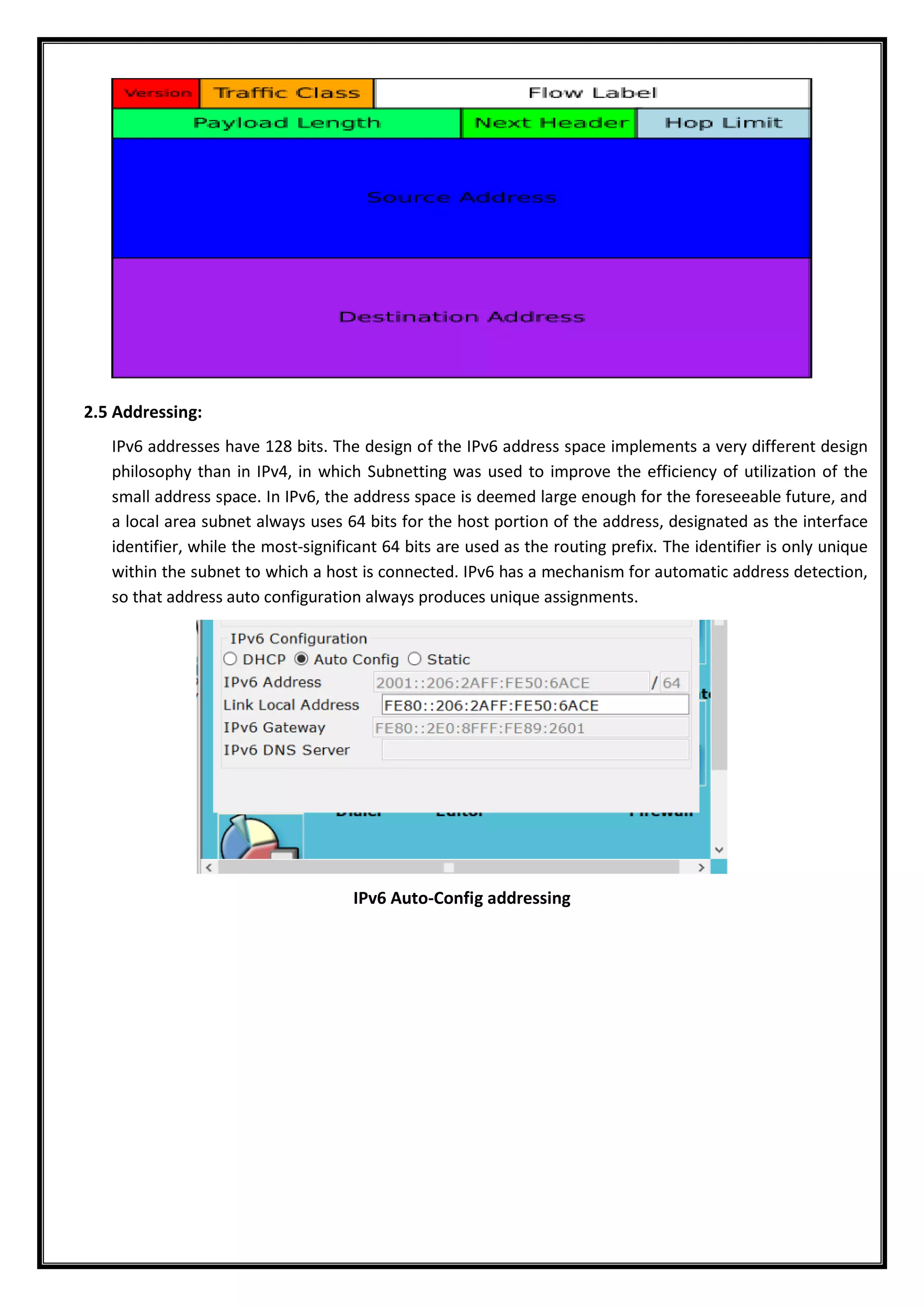
![2. IPV6(Internet Protocol Version 6)
2.1 Introduction
Internet Protocol version 6 (IPv6) is the most recent version of the Internet Protocol (IP), the
communications protocol that provides an identification and location system for computers on
networks and routes traffic across the Internet. IPv6 was developed by the Internet Engineering Task
Force (IETF) to deal with the long-anticipated problem of IPv4 address exhaustion. IPv6 is intended to
replace IPv4.
Every device on the Internet is assigned a unique IP address for identification and location definition.
With the rapid growth of the Internet after commercialization in the 1990s, it became evident that far
more addresses would be needed to connect devices than the IPv4 address space had available. By
1998, the Internet Engineering Task Force (IETF) had formalized the successor protocol. IPv6 uses a 128-
bit address, theoretically allowing 2128
, or approximately 3.4×1038
addresses. The actual number is
slightly smaller, as multiple ranges are reserved for special use or completely excluded from use. The
total number of possible IPv6 addresses is more than 7.9×1028
times as many as IPv4, which uses 32-bit
addresses and provides approximately 4.3 billion addresses. The two protocols are not designed to be
interoperable, complicating the transition to IPv6. However, several IPv6 transition mechanisms have
been devised to permit communication between IPv4 and IPv6 hosts.
IPv6 provides other technical benefits in addition to a larger addressing space. In particular, it permits
hierarchical address allocation methods that facilitate route aggregation across the Internet, and thus
limit the expansion of routing tables. The use of multicast addressing is expanded and simplified, and
provides additional optimization for the delivery of services. Device mobility, security, and configuration
aspects have been considered in the design of the protocol.
IPv6 addresses are represented as eight groups of four hexadecimal digits with the groups being
separated by colons, for example 2001:0db8:0000:0042:0000:8a2e:0370:7334, but methods to
abbreviate this full notation exist.
2.2 Motivation and Origin:
Internet Protocol Version 4 (IPv4) was the first publicly used version of the Internet Protocol. IPv4 was
developed as a research project by the Defense Advanced Research Projects Agency (DARPA), a United
States Department of Defense agency, before becoming the foundation for the Internet and the World
Wide Web. It is currently described by IETF publication RFC 791 (September 1981), which replaced an
earlier definition (RFC 760, January 1980). IPv4 included an addressing system that used numerical
identifiers consisting of 32 bits. These addresses are typically displayed in quad-dotted notation as
decimal values of four octets, each in the range 0 to 255, or 8 bits per number. Thus, IPv4 provides an
addressing capability of 232
or approximately 4.3 billion addresses. Address exhaustion was not initially a
concern in IPv4 as this version was originally presumed to be a test of DARPA's networking concepts.[5]
During the first decade of operation of the Internet, it became apparent that methods had to be
developed to conserve address space. In the early 1990s, even after the redesign of the addressing
system using a classless network model, it became clear that this would not suffice to prevent IPv4
address exhaustion, and that further changes to the Internet infrastructure were needed.
The last unassigned top-level address blocks of 16 million IPv4 addresses were allocated in February
2011 by the Internet Assigned Numbers Authority (IANA) to the five regional Internet registries (RIRs).
However, each RIR still has available address pools and is expected to continue with standard address
allocation policies until one /8 Classless Inter-Domain Routing (CIDR) block remains. After that, only](https://image.slidesharecdn.com/finalreportcn-180224162151/75/Private-Network-Project-for-Colleges-35-2048.jpg)