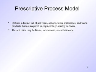
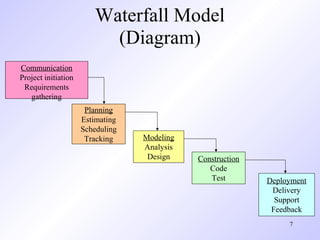
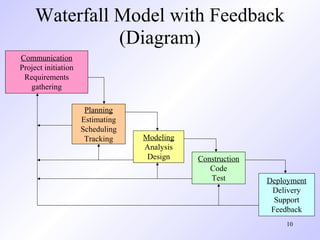
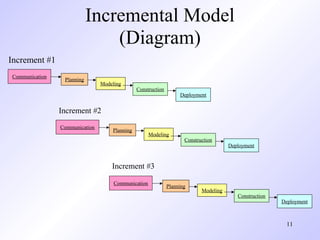
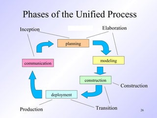
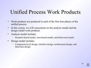
Chapter 3
 Prescriptive Process
       Models
      - Generic process framework (revisited)
      - Traditional process models
      - Specialized process models
      - The unified process


(Source: Pressman, R. Software Engineering: A Practitioner’s Approach. McGraw-Hill, 2005)
Generic Process Framework
• Communication
    – Involves communication among the customer and other stake holders; encompasses
      requirements gathering
• Planning
    – Establishes a plan for software engineering work; addresses technical tasks,
      resources, work products, and work schedule
• Modeling (Analyze, Design)
    – Encompasses the creation of models to better under the requirements and the
      design
• Construction (Code, Test)
    – Combines code generation and testing to uncover errors
• Deployment
    – Involves delivery of software to the customer for evaluation and feedback


                                                                                     2
Modeling: Software Requirements
             Analysis
• Helps software engineers to better understand the problem they will
  work to solve
• Encompasses the set of tasks that lead to an understanding of what the
  business impact of the software will be, what the customer wants, and
  how end-users will interact with the software
• Uses a combination of text and diagrams to depict requirements for
  data, function, and behavior
    – Provides a relatively easy way to understand and review requirements for
      correctness, completeness and consistency


                                                                                 3
Modeling: Software Design
• Brings together customer requirements, business needs, and technical
  considerations to form the “blueprint” for a product
• Creates a model that that provides detail about software data structures,
  software architecture, interfaces, and components that are necessary to
  implement the system
• Architectural design
    – Represents the structure of data and program components that are required to build
      the software
    – Considers the architectural style, the structure and properties of components that
      constitute the system, and interrelationships that occur among all architectural
      components
• User Interface Design
    – Creates an effective communication medium between a human and a computer
    – Identifies interface objects and actions and then creates a screen layout that forms
      the basis for a user interface prototype
• Component-level Design
    – Defines the data structures, algorithms, interface characteristics, and communication
      mechanisms allocated to each software component

                                                                                      4
Traditional Process Models
Prescriptive Process Model

• Defines a distinct set of activities, actions, tasks, milestones, and work
  products that are required to engineer high-quality software
• The activities may be linear, incremental, or evolutionary


                                                                               6
Waterfall Model
                          (Diagram)
Communication
Project initiation
 Requirements
   gathering
                      Planning
                     Estimating
                     Scheduling
                      Tracking    Modeling
                                  Analysis
                                   Design    Construction
                                                Code
                                                Test        Deployment
                                                             Delivery
                                                              Support
                                                             Feedback
                                                                 7
Waterfall Model
                     (Description)
• Oldest software lifecycle model and best understood by upper management
• Used when requirements are well understood and risk is low
• Work flow is in a linear (i.e., sequential) fashion
• Used often with well-defined adaptations or enhancements to current
  software


                                                                        8
Waterfall Model
                     (Problems)
• Doesn't support iteration, so changes can cause confusion
• Difficult for customers to state all requirements explicitly and up front
• Requires customer patience because a working version of the program
  doesn't occur until the final phase
• Problems can be somewhat alleviated in the model through the addition of
  feedback loops (see the next slide)


                                                                         9
Waterfall Model with Feedback
               (Diagram)
Communication
Project initiation
 Requirements
   gathering

                      Planning
                     Estimating
                     Scheduling
                      Tracking    Modeling
                                  Analysis
                                   Design    Construction
                                                Code
                                                Test        Deployment
                                                             Delivery
                                                              Support
                                                             Feedback
                                                                10
Incremental Model
                                (Diagram)
Increment #1
Communication
                 Planning
                                Modeling
                                               Construction
                                                                   Deployment


                Increment #2
                Communication
                                    Planning
                                                     Modeling
                                                                     Construction
                                                                                       Deployment


                                    Increment #3

                                     Communication
                                                              Planning
                                                                            Modeling
                                                                                          Construction
                                                                                                         Deployment


                                                                                                          11
Incremental Model
                     (Description)
• Used when requirements are well understood
• Multiple independent deliveries are identified
• Work flow is in a linear (i.e., sequential) fashion within an increment and is
  staggered between increments
• Iterative in nature; focuses on an operational product with each increment
• Provides a needed set of functionality sooner while delivering optional
  components later
• Useful also when staffing is too short for a full-scale development


                                                                           12
Prototyping Model
                  (Diagram)
                                Quick
                               Planning

        Communication
Start

                                           Modeling
                                          Quick Design
        Deployment,
          Delivery,
        and Feedback


                        Construction
                        Of Prototype
                                                         13
Prototyping Model
                    (Description)
• Follows an evolutionary and iterative approach
• Used when requirements are not well understood
• Serves as a mechanism for identifying software requirements
• Focuses on those aspects of the software that are visible to the customer/user
• Feedback is used to refine the prototype


                                                                          14
Prototyping Model
                  (Potential Problems)
• The customer sees a "working version" of the software, wants to stop all
  development and then buy the prototype after a "few fixes" are made
• Developers often make implementation compromises to get the software
  running quickly (e.g., language choice, user interface, operating system
  choice, inefficient algorithms)
• Lesson learned
    – Define the rules up front on the final disposition of the prototype before it is
      built
    – In most circumstances, plan to discard the prototype and engineer the actual
      production software with a goal toward quality


                                                                                     15
Spiral Model
                 (Diagram)
                      Planning

Communication


Start                                           Modeling


Start


        Deployment               Construction

                                                           16
Spiral Model
                           (Description)
•   Invented by Dr. Barry Boehm in 1988 while working at TRW
•   Follows an evolutionary approach
•   Used when requirements are not well understood and risks are high
•   Inner spirals focus on identifying software requirements and project risks; may
    also incorporate prototyping
•   Outer spirals take on a classical waterfall approach after requirements have been
    defined, but permit iterative growth of the software
•   Operates as a risk-driven model…a go/no-go decision occurs after each
    complete spiral in order to react to risk determinations
•   Requires considerable expertise in risk assessment
•   Serves as a realistic model for large-scale software development


                                                                              17
General Weaknesses of
     Evolutionary Process Models
1)   Prototyping poses a problem to project planning because of the
     uncertain number of iterations required to construct the product
2)   Evolutionary software processes do not establish the maximum speed of
     the evolution
     •   If too fast, the process will fall into chaos
     •   If too slow, productivity could be affected
1)   Software processes should focus first on flexibility and extensibility, and
     second on high quality
     •   We should prioritize the speed of the development over zero defects
     •   Extending the development in order to reach higher quality could result in
         late delivery


                                                                               18
Specialized Process Models
Component-based Development Model
• Consists of the following process steps
    – Available component-based products are researched and evaluated for the
      application domain in question
    – Component integration issues are considered
    – A software architecture is designed to accommodate the components
    – Components are integrated into the architecture
    – Comprehensive testing is conducted to ensure proper functionality
• Relies on a robust component library
• Capitalizes on software reuse, which leads to documented savings in
  project cost and time


                                                                            20
Formal Methods Model
              (Description)
• Encompasses a set of activities that leads to formal mathematical
  specification of computer software
• Enables a software engineer to specify, develop, and verify a
  computer-based system by applying a rigorous, mathematical notation
• Ambiguity, incompleteness, and inconsistency can be discovered and
  corrected more easily through mathematical analysis
• Offers the promise of defect-free software
• Used often when building safety-critical systems


                                                                    21
Formal Methods Model
              (Challenges)
• Development of formal methods is currently quite time-consuming and
  expensive
• Because few software developers have the necessary background to
  apply formal methods, extensive training is required
• It is difficult to use the models as a communication mechanism for
  technically unsophisticated customers


                                                                   22
The Unified Process
Background
• Birthed during the late 1980's and early 1990s when object-oriented
  languages were gaining wide-spread use
• Many object-oriented analysis and design methods were proposed;
  three top authors were Grady Booch, Ivar Jacobson, and James
  Rumbaugh
• They eventually worked together on a unified method, called the
  Unified Modeling Language (UML)
    – UML is a robust notation for the modeling and development of object-
      oriented systems
    – UML became an industry standard in 1997
    – However, UML does not provide the process framework, only the
      necessary technology for object-oriented development


                                                                             24
Background (continued)
• Booch, Jacobson, and Rumbaugh later developed the unified process,
  which is a framework for object-oriented software engineering using
  UML
    – Draws on the best features and characteristics of conventional software
      process models
    – Emphasizes the important role of software architecture
    – Consists of a process flow that is iterative and incremental, thereby
      providing an evolutionary feel
• Consists of five phases: inception, elaboration, construction, transition,
  and production


                                                                                25
Phases of the Unified Process
Inception                               Elaboration

                    planning


                                       modeling
  communication


                               construction
                                                  Construction
              deployment


Production                           Transition           26
Inception Phase

• Encompasses both customer communication and planning activities of the
  generic process
• Business requirements for the software are identified
• A rough architecture for the system is proposed
• A plan is created for an incremental, iterative development
• Fundamental business requirements are described through preliminary use
  cases
    – A use case describes a sequence of actions that are performed by a user


                                                                                27
Elaboration Phase
• Encompasses both the planning and modeling activities of the generic process
• Refines and expands the preliminary use cases
• Expands the architectural representation to include five views
    –   Use-case model
    –   Analysis model
    –   Design model
    –   Implementation model
    –   Deployment model
• Often results in an executable architectural baseline that represents a first cut
  executable system
• The baseline demonstrates the viability of the architecture but does not provide
  all features and functions required to use the system


                                                                             28
Construction Phase

• Encompasses the construction activity of the generic process
• Uses the architectural model from the elaboration phase as input
• Develops or acquires the software components that make each use-case
  operational
• Analysis and design models from the previous phase are completed to reflect the
  final version of the increment
• Use cases are used to derive a set of acceptance tests that are executed prior to
  the next phase


                                                                          29
Transition Phase

• Encompasses the last part of the construction activity and the first part of the
  deployment activity of the generic process
• Software is given to end users for beta testing and user feedback reports on
  defects and necessary changes
• The software teams create necessary support documentation (user manuals,
  trouble-shooting guides, installation procedures)
• At the conclusion of this phase, the software increment becomes a usable
  software release


                                                                             30
Production Phase
•   Encompasses the last part of the deployment activity of the generic process
•   On-going use of the software is monitored
•   Support for the operating environment (infrastructure) is provided
•   Defect reports and requests for changes are submitted and evaluated


                                                                            31
Unified Process Work Products
• Work products are produced in each of the first four phases of the
  unified process
• In this course, we will concentrate on the analysis model and the
  design model work products
• Analysis model includes
    – Scenario-based model, class-based model, and behavioral model
• Design model includes
    – Component-level design, interface design, architectural design, and
      data/class design


                                                                            32
                                                                                 

Pressman ch-3-prescriptive-process-models

  • 1.
    Chapter 3 PrescriptiveProcess Models - Generic process framework (revisited) - Traditional process models - Specialized process models - The unified process (Source: Pressman, R. Software Engineering: A Practitioner’s Approach. McGraw-Hill, 2005)
  • 2.
    Generic Process Framework •Communication – Involves communication among the customer and other stake holders; encompasses requirements gathering • Planning – Establishes a plan for software engineering work; addresses technical tasks, resources, work products, and work schedule • Modeling (Analyze, Design) – Encompasses the creation of models to better under the requirements and the design • Construction (Code, Test) – Combines code generation and testing to uncover errors • Deployment – Involves delivery of software to the customer for evaluation and feedback 2
  • 3.
    Modeling: Software Requirements Analysis • Helps software engineers to better understand the problem they will work to solve • Encompasses the set of tasks that lead to an understanding of what the business impact of the software will be, what the customer wants, and how end-users will interact with the software • Uses a combination of text and diagrams to depict requirements for data, function, and behavior – Provides a relatively easy way to understand and review requirements for correctness, completeness and consistency 3
  • 4.
    Modeling: Software Design •Brings together customer requirements, business needs, and technical considerations to form the “blueprint” for a product • Creates a model that that provides detail about software data structures, software architecture, interfaces, and components that are necessary to implement the system • Architectural design – Represents the structure of data and program components that are required to build the software – Considers the architectural style, the structure and properties of components that constitute the system, and interrelationships that occur among all architectural components • User Interface Design – Creates an effective communication medium between a human and a computer – Identifies interface objects and actions and then creates a screen layout that forms the basis for a user interface prototype • Component-level Design – Defines the data structures, algorithms, interface characteristics, and communication mechanisms allocated to each software component 4
  • 5.
  • 6.
    Prescriptive Process Model •Defines a distinct set of activities, actions, tasks, milestones, and work products that are required to engineer high-quality software • The activities may be linear, incremental, or evolutionary 6
  • 7.
    Waterfall Model (Diagram) Communication Project initiation Requirements gathering Planning Estimating Scheduling Tracking Modeling Analysis Design Construction Code Test Deployment Delivery Support Feedback 7
  • 8.
    Waterfall Model (Description) • Oldest software lifecycle model and best understood by upper management • Used when requirements are well understood and risk is low • Work flow is in a linear (i.e., sequential) fashion • Used often with well-defined adaptations or enhancements to current software 8
  • 9.
    Waterfall Model (Problems) • Doesn't support iteration, so changes can cause confusion • Difficult for customers to state all requirements explicitly and up front • Requires customer patience because a working version of the program doesn't occur until the final phase • Problems can be somewhat alleviated in the model through the addition of feedback loops (see the next slide) 9
  • 10.
    Waterfall Model withFeedback (Diagram) Communication Project initiation Requirements gathering Planning Estimating Scheduling Tracking Modeling Analysis Design Construction Code Test Deployment Delivery Support Feedback 10
  • 11.
    Incremental Model (Diagram) Increment #1 Communication Planning Modeling Construction Deployment Increment #2 Communication Planning Modeling Construction Deployment Increment #3 Communication Planning Modeling Construction Deployment 11
  • 12.
    Incremental Model (Description) • Used when requirements are well understood • Multiple independent deliveries are identified • Work flow is in a linear (i.e., sequential) fashion within an increment and is staggered between increments • Iterative in nature; focuses on an operational product with each increment • Provides a needed set of functionality sooner while delivering optional components later • Useful also when staffing is too short for a full-scale development 12
  • 13.
    Prototyping Model (Diagram) Quick Planning Communication Start Modeling Quick Design Deployment, Delivery, and Feedback Construction Of Prototype 13
  • 14.
    Prototyping Model (Description) • Follows an evolutionary and iterative approach • Used when requirements are not well understood • Serves as a mechanism for identifying software requirements • Focuses on those aspects of the software that are visible to the customer/user • Feedback is used to refine the prototype 14
  • 15.
    Prototyping Model (Potential Problems) • The customer sees a "working version" of the software, wants to stop all development and then buy the prototype after a "few fixes" are made • Developers often make implementation compromises to get the software running quickly (e.g., language choice, user interface, operating system choice, inefficient algorithms) • Lesson learned – Define the rules up front on the final disposition of the prototype before it is built – In most circumstances, plan to discard the prototype and engineer the actual production software with a goal toward quality 15
  • 16.
    Spiral Model (Diagram) Planning Communication Start Modeling Start Deployment Construction 16
  • 17.
    Spiral Model (Description) • Invented by Dr. Barry Boehm in 1988 while working at TRW • Follows an evolutionary approach • Used when requirements are not well understood and risks are high • Inner spirals focus on identifying software requirements and project risks; may also incorporate prototyping • Outer spirals take on a classical waterfall approach after requirements have been defined, but permit iterative growth of the software • Operates as a risk-driven model…a go/no-go decision occurs after each complete spiral in order to react to risk determinations • Requires considerable expertise in risk assessment • Serves as a realistic model for large-scale software development 17
  • 18.
    General Weaknesses of Evolutionary Process Models 1) Prototyping poses a problem to project planning because of the uncertain number of iterations required to construct the product 2) Evolutionary software processes do not establish the maximum speed of the evolution • If too fast, the process will fall into chaos • If too slow, productivity could be affected 1) Software processes should focus first on flexibility and extensibility, and second on high quality • We should prioritize the speed of the development over zero defects • Extending the development in order to reach higher quality could result in late delivery 18
  • 19.
  • 20.
    Component-based Development Model •Consists of the following process steps – Available component-based products are researched and evaluated for the application domain in question – Component integration issues are considered – A software architecture is designed to accommodate the components – Components are integrated into the architecture – Comprehensive testing is conducted to ensure proper functionality • Relies on a robust component library • Capitalizes on software reuse, which leads to documented savings in project cost and time 20
  • 21.
    Formal Methods Model (Description) • Encompasses a set of activities that leads to formal mathematical specification of computer software • Enables a software engineer to specify, develop, and verify a computer-based system by applying a rigorous, mathematical notation • Ambiguity, incompleteness, and inconsistency can be discovered and corrected more easily through mathematical analysis • Offers the promise of defect-free software • Used often when building safety-critical systems 21
  • 22.
    Formal Methods Model (Challenges) • Development of formal methods is currently quite time-consuming and expensive • Because few software developers have the necessary background to apply formal methods, extensive training is required • It is difficult to use the models as a communication mechanism for technically unsophisticated customers 22
  • 23.
  • 24.
    Background • Birthed duringthe late 1980's and early 1990s when object-oriented languages were gaining wide-spread use • Many object-oriented analysis and design methods were proposed; three top authors were Grady Booch, Ivar Jacobson, and James Rumbaugh • They eventually worked together on a unified method, called the Unified Modeling Language (UML) – UML is a robust notation for the modeling and development of object- oriented systems – UML became an industry standard in 1997 – However, UML does not provide the process framework, only the necessary technology for object-oriented development 24
  • 25.
    Background (continued) • Booch,Jacobson, and Rumbaugh later developed the unified process, which is a framework for object-oriented software engineering using UML – Draws on the best features and characteristics of conventional software process models – Emphasizes the important role of software architecture – Consists of a process flow that is iterative and incremental, thereby providing an evolutionary feel • Consists of five phases: inception, elaboration, construction, transition, and production 25
  • 26.
    Phases of theUnified Process Inception Elaboration planning modeling communication construction Construction deployment Production Transition 26
  • 27.
    Inception Phase • Encompassesboth customer communication and planning activities of the generic process • Business requirements for the software are identified • A rough architecture for the system is proposed • A plan is created for an incremental, iterative development • Fundamental business requirements are described through preliminary use cases – A use case describes a sequence of actions that are performed by a user 27
  • 28.
    Elaboration Phase • Encompassesboth the planning and modeling activities of the generic process • Refines and expands the preliminary use cases • Expands the architectural representation to include five views – Use-case model – Analysis model – Design model – Implementation model – Deployment model • Often results in an executable architectural baseline that represents a first cut executable system • The baseline demonstrates the viability of the architecture but does not provide all features and functions required to use the system 28
  • 29.
    Construction Phase • Encompassesthe construction activity of the generic process • Uses the architectural model from the elaboration phase as input • Develops or acquires the software components that make each use-case operational • Analysis and design models from the previous phase are completed to reflect the final version of the increment • Use cases are used to derive a set of acceptance tests that are executed prior to the next phase 29
  • 30.
    Transition Phase • Encompassesthe last part of the construction activity and the first part of the deployment activity of the generic process • Software is given to end users for beta testing and user feedback reports on defects and necessary changes • The software teams create necessary support documentation (user manuals, trouble-shooting guides, installation procedures) • At the conclusion of this phase, the software increment becomes a usable software release 30
  • 31.
    Production Phase • Encompasses the last part of the deployment activity of the generic process • On-going use of the software is monitored • Support for the operating environment (infrastructure) is provided • Defect reports and requests for changes are submitted and evaluated 31
  • 32.
    Unified Process WorkProducts • Work products are produced in each of the first four phases of the unified process • In this course, we will concentrate on the analysis model and the design model work products • Analysis model includes – Scenario-based model, class-based model, and behavioral model • Design model includes – Component-level design, interface design, architectural design, and data/class design 32 