Downloaded 151 times


![13 UML Applied - Object Oriented Analysis and Design using the UML
• The process is commonly associated with Rapid Application Development, which
is considered by many to be a hacker's charter.
• The process is much more difficult to manage. The Waterfall Model fits in closely
with classic project management techniques such as Gantt charts, but spiral
processes require a different approach.
To counteract the drawbacks of the spiral technical, let's look at a similar, but more
formal approach called an Iterative, Incremental Framework.
Philippe Kruchten’s Whitepaper (reference [5], available from Rational
Software’s website) explores the traps many managers are likely to face on
their first iterative development.
Iterative, Incremental Frameworks
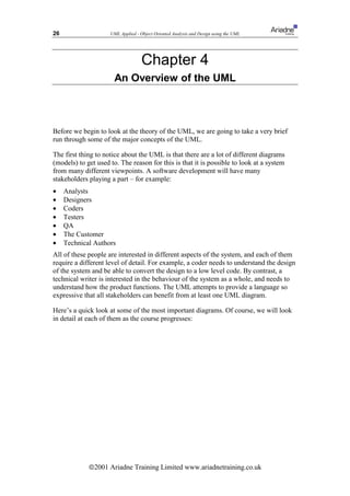
The Iterative, Incremental Framework is a logical extension to the spiral model, but is
more formal and rigorous. We will be following an Iterative, Incremental Framework
through the rest of this course.
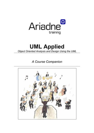
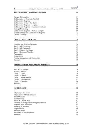
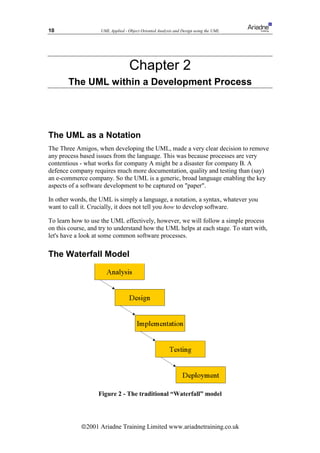
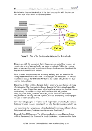
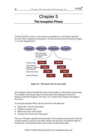
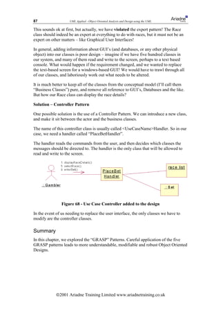
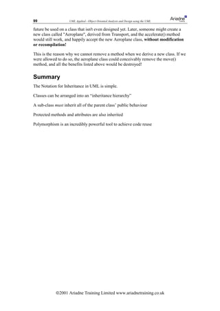
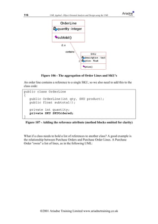
The framework is divided into four major phases: Inception; Elaboration;
Construction and Transition. These phases are performed in sequence, but the
phases must not be confused with the stages in the waterfall lifecycle. This section
describes the phases and outlines the activities performed during each one.
Figure 5 - the four phases of an Iterative, Incremental Framework
Inception
The inception phase is concerned with establishing the scope of the project and
generally defining a vision for the project. For a small project, this phase could be a
simple chat over coffee and an agreement to proceed; on larger projects, a more
thorough inception is necessary. Possible deliverables from this phase are:
• A Vision Document
• An initial exploration of the customer’s requirements
• A first-cut project glossary (more on this later)
• A Business Case (including success criteria and a financial forecast, estimates of
the Return on Investment, etc)
• An initial risk assessment
ã2001 Ariadne Training Limited www.ariadnetraining.co.uk](https://image.slidesharecdn.com/umlapplied-100901233853-phpapp01/85/UML-Applied-13-320.jpg)
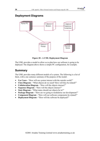
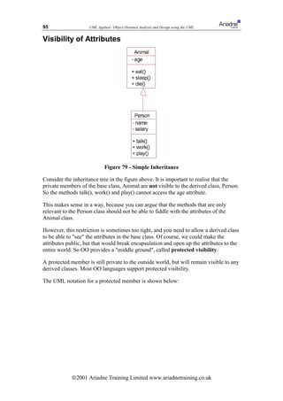
![15 UML Applied - Object Oriented Analysis and Design using the UML
At the end of as many iterations as possible, we will aim to have a running system
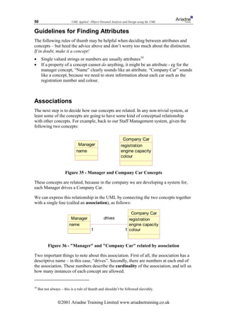
(albeit, of course, a very limited system in the early stages). These iterations are called
Increments, hence the name of the framework!
Transition
The final phase is concerned with moving the final product across to the customers.
Typical activities in this phase include:
• Beta-releases for testing by the user community
• Factory testing, or running the product in parallel with the legacy system that the
product is replacing
• Data takeon (ie converting existing databases across to new formats, importing
data, etc)
• Training the new users
• Marketing, Distribution and Sales
The Transition phase should not be confused with the traditional test phase at the end
of the waterfall model. At the start of Transition, a full, tested and running product
should be available for the users. As listed above, some projects may require a beta-
test stage, but the product should be pretty much complete before this phase happens.
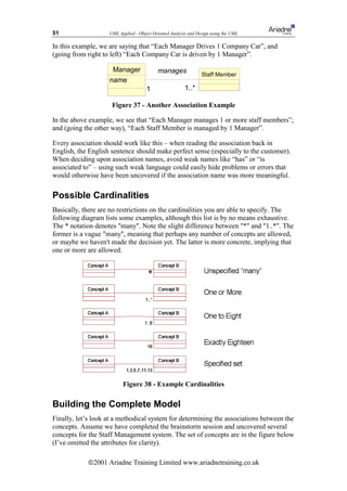
How Many Iterations? How Long Should They Be?
A single iteration should typically last between 2 weeks and 2 months. Any more than
two months leads to an increase in complexity and the inevitable “big bang”
integration stage, where many software components have to be integrated for the first
time.
A bigger and more complex project should not automatically imply the need for
longer iterations – this will increase the level of complexity the developers need to
handle at any one time. Rather, a bigger project should require more iterations.
Some factors that should influence the iteration length include: (see Larman [2],
pp447-448).
• Early development cycles may need to be longer. This gives developers a chance
to perform exploratory work on untested or new technology, or to define the
infrastructure for the project.
• Novice staff
• Parallel developments teams
• Distributed (eg cross site) teams [note that Larman even includes in this category
any team where the members are not all located on the same floor, even if they are
in the same building!]
To this list, I would also add that a high ceremony project will generally need longer
iterations. A high ceremony project is one which might have to deliver a lot of project
documentation to the customer, or perhaps a project which must meet a lot of legal
requirements. A very good example would be any defence related project. In this case,
the documentary work will extend the length of the iteration – but the amount of
ã2001 Ariadne Training Limited www.ariadnetraining.co.uk](https://image.slidesharecdn.com/umlapplied-100901233853-phpapp01/85/UML-Applied-15-320.jpg)
![16 UML Applied - Object Oriented Analysis and Design using the UML
software development tackled in the iteration should still be kept to a minimum to
avoid our chief enemy, complexity overload.
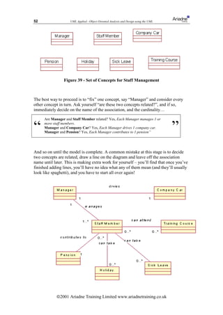
Time Boxing
A radical approach to managing an iterative, incremental process is Time Boxing. This
is a rigid approach which sets a fixed time period in which a particular iteration must
be completed by.
If an iteration is not complete by the end of the timebox, the iteration ends anyway.
The crucial activity associated with timeboxing is the review at the end of iteration.
The review must explore the reasons for any delays, and must reschedule any
unfinished work into future iterations.
Larman (ref [2]) gives details on how to implement timeboxing. One of his
recommendations is that the developers be responsible for (or at least, have a large say
in) setting which requirements are covered in each iteration, as they are the ones who
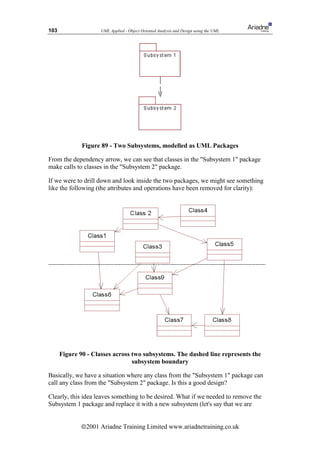
will have to meet the deadlines.
Implementing timeboxing is difficult. It requires a culture of extreme discipline
through the entire project. It is extremely tempting to forgo the review and overstep
the timebox if the iteration is “99%” complete when the deadline arrives. Once a
project succumbs to temptation and one review is missed, the whole concept begins to
fall apart. Many reviews are missed, future iterations planning becomes sloppy and
chaos begins to set in.
Some managers assume that timeboxing prevents slippage. It does not. If an iteration
is not complete once the timebox has expired, then the unfinished work must be
reallocated to later iterations, and the iteration plans are reworked – this could include
slipping the delivery date or adding more iterations. However, the benefits of
timeboxing are:
• The rigid structure enforces planning and replanning. Plans are not discarded once
the project begins to slip
• If timeboxes are enforced, there is less of a tendency for the project to descend
into chaos once problems emerge, as there is always a formal timebox review not
too far away
• If panic sets in and developers start to furiously hack, the hacking is stemmed
once the review is held
Essentially, timeboxing allows the entire project to regularly “stand back” and take
stock. It does not prevent slippage, and requires strong project management to work.
Typical Project Timings
How long should each of the four phases last? This is entirely up to individual
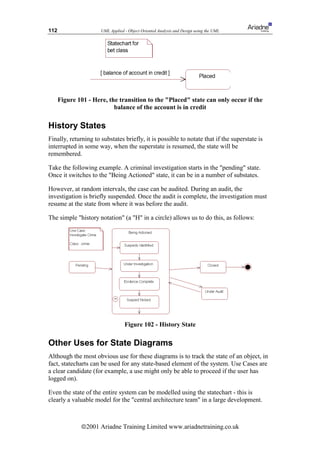
projects, but a loose guideline is 10% inception, 30% elaboration, 50% construction
and 10% transition.
ã2001 Ariadne Training Limited www.ariadnetraining.co.uk](https://image.slidesharecdn.com/umlapplied-100901233853-phpapp01/85/UML-Applied-16-320.jpg)


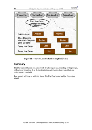
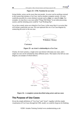
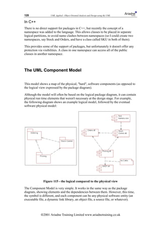
![37 UML Applied - Object Oriented Analysis and Design using the UML
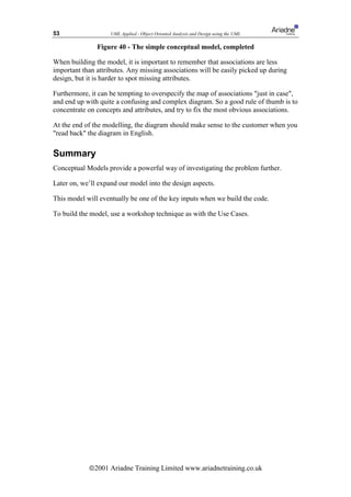
Chapter 6
The Elaboration Phase
In the Elaboration Phase, we are concerned with exploring the problem in detail,
understanding the customer’s requirements and their business, and to develop the plan
further.
We must get in to the correct frame of mind to attack this phase correctly. We must
try not to get bogged down with too much detail – especially implementation details.
We need to have a very broad view of the system and understand system-wide issues.
Kruchten (ref [1]) calls this a mile wide and inch deep view.
Prototyping
A key activity in the Elaboration Phase is the mitigation of risks. The sooner risks are
identified and shot down, the lesser their impact will be on the project.
Prototyping difficult or problematic areas of the project are a tremendous help in the
mitigation of risks. Given that we don't want to get bogged down in implementation
and design at this phase, the prototypes should be very focussed, and explore just the
area of concern.
Prototypes can be thrown away at the end of the exercise, or they can be reused during
the construction phase.
Deliverables
Apart from prototypes, we are going to develop two UML models to help us towards
our goal of understanding the problem as a whole.
The first model is the Use Case Model. This will help us to understand what the
system needs to do, and what it should look like to the outside world (ie the users,
or perhaps the systems it must interface to).
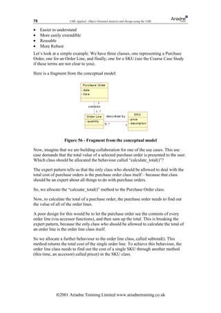
The second model is the Conceptual Model. This model allows us to capture, using
UML, a graphical statement of the customer's problem. It will describe all of the
major concepts in the customer's problem, and how they are related. To build this,
we'll use the UML Class Diagram. We will use this Conceptual Model in the
Construction Phase to build our software classes and objects.
We'll cover these two models, in depth, in the next two chapters.
ã2001 Ariadne Training Limited www.ariadnetraining.co.uk](https://image.slidesharecdn.com/umlapplied-100901233853-phpapp01/85/UML-Applied-37-320.jpg)
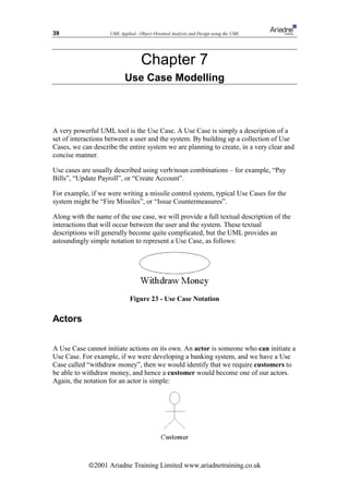
![41 UML Applied - Object Oriented Analysis and Design using the UML
that Use Cases are simple – almost too simple to worry about. Wrong. Use Cases are
immensely powerful.
• Use Cases define the scope of the System. They enable us to visualise size and
scope of the entire development.
• Use Cases are very similar to requirements, but whilst requirements tend to be
vague, confusing, ambiguous and poorly written, the tighter structure of Use
Cases tend to make them far more focused
• The “sum” of the use cases is the whole system. That means that anything not
covered by a use case is outside the boundary of the system we are developing.
So the Use Case diagram is complete, with no holes.
• They allow for communication between the customer and developers (since the
diagram is so simple, anyone can understand it)
• Use Cases guide the development teams through the development process – we
shall see that Use Cases are the backbone of our development, and we refer to
them in everything we do
• We’ll see that Use Cases provide a method for planning our development work,
and allow us to estimate how long the development will take
• Use Cases provide the basis for creating system tests
• Finally, Use Cases help with the creation of user guides!
It is often claimed that Use Cases are simply an expression of the system
requirements. Anyone making this claim are clearly missing the point of Use Cases!8
Use Case Granularity
It can be difficult to decide upon the granularity of use cases – in a particular scenario,
should each user-system interaction be a use case, or should the use case encapsulate
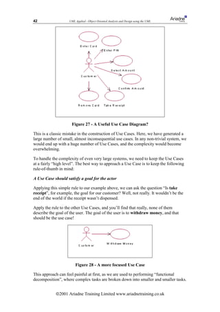
all of the interactions? For example, let us consider the example of the ATM machine.
We need to build the ATM system to allow a user to withdraw money. We might have
the following series of common interactions in this scenario:
• enter card
• enter pin number
• select amount required
• confirm amount required
• remove card
• take receipt
Should each of these steps – for example, “enter pin number” be a use case?
8
Though, of course, Use Cases are closely related to requirements. See reference [9] for an excellent
treatment on requirements through Use Cases
ã2001 Ariadne Training Limited www.ariadnetraining.co.uk](https://image.slidesharecdn.com/umlapplied-100901233853-phpapp01/85/UML-Applied-41-320.jpg)
![47 UML Applied - Object Oriented Analysis and Design using the UML
On the conceptual model, we aim to capture all of the concepts or ideas that the
customer recognises. For example, some good examples of concepts would be:
• Lift in a lift control system
• Order in a home shopping system
• Footballer in a football transfers system (or a PlayStation football game!)
• Trainer in a stock management system for a shoe shop
• Room in a room booking system
Some very bad examples of concepts are:
• OrderPurgeDaemon the process that regularly deletes old orders from the system
• EventTrigger – the special process that waits for 5 minutes and then tells the
system to wake up and do something
• CustomerDetailsForm – the window that asks for details of the new customer in
a shopping system
• DbArchiveTable – the database table holding a list of all old orders
These are bad concepts, because they are focussing on design – the solution, and not
the problem. In the DbArchiveTable example, we are already tying ourselves down to
a relational database solution. What if it turns out later that it is more efficient,
cheaper, and perfectly acceptable to use a simple text file?
The best rule of thumb here is:
If the customer doesn’t understand the concept, it probably isn’t a concept!
Designers hate the conceptual step – they cannot wait to crack on with design. We
shall see, however, that the conceptual model will slowly transform into a full design
class diagram as we move through the construction phase.
Finding Concepts
I recommend a similar approach to finding Use Cases – a workshop is best – once
again, with as many interested stakeholders as possible.
Brainstorm suggestions for concepts, capture all the suggestions. Once brainstorming
is complete, work as a group to discuss and justify each suggestion. Apply the rule of
thumb that the customer must understand the concept, and discard any that don’t
apply to the problem, and discard any that are touching on design.
Extracting Concepts From Requirements
The requirements document is a good source of concepts. Craig Larman (ref [2])
suggests the following candidate concepts from the requirements:
• Physical or tangible objects
• Places
• Transactions
• Roles of People (eg Customer, Sales Clerk)
• Containers for other Concepts
• Other Systems external to the system (eg Remote Database)
ã2001 Ariadne Training Limited www.ariadnetraining.co.uk](https://image.slidesharecdn.com/umlapplied-100901233853-phpapp01/85/UML-Applied-47-320.jpg)


![60 UML Applied - Object Oriented Analysis and Design using the UML
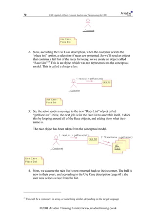
(1) On initiation of Place Bet by the gambler, a list of the day’s races are requested
from the system, and (2) the list of races are displayed
(3) The Gambler chooses the race to bet on [A1] and (4) the system presents a list of
the runners for that race
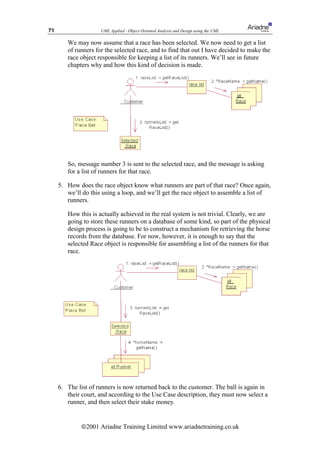
(5) The Gambler chooses the horse to bet on [A1] and enters the required stake [E1]
(6) The User Confirms the transaction and (7) the system displays a confirmation
message
Notice that every actor/system interaction is broken down into steps. In this case,
there are seven steps in the main flow of the Use Case. The [A1] and [E1] notation
will be explained in a moment, when we look at Alternate Flows and Exception
Flows.
Alternate Flows
Alternate flows are simply less common (but legitimate) flows through the Use Case.
The alternate flow will typically share many steps with the main flow, so we can
notate the point in the main flow where the alternate flow takes over. We have done
this in step (3) of the main flow above, through the [A1] notation. This is because
when the user chooses the race to bet on, they can cancel the transaction. They can
also cancel the transaction at step 5, when they are required to enter the stake.
“(A1) The User Cancels the Transaction
Post Condition - No bets were placed”
In this case, the Alternate flow has resulted in a change to the post condition – no bets
were placed.11
Exception Flows
Finally, the exception flow describes exceptional situations. In other words, a flow
where an error has occurred, or an event that couldn’t have otherwise been predicted.
In our place bet example, we could have the following exception:
“(E1) The users credit is not sufficient to fund the bet. The User is informed and the
Use Case terminates”
When we move to program code. the items under Exception Flow should map to
exceptions in the program - if your target language supports exceptions. Many modern
languages do support them - Java, C++, Delphi and Ada to name but four.
11
Some UML practitioners prefer to say that an alternate flow will always result in the same post
conditions as the main flow. Another example where the UML can be applied in many different ways. I
prefer to allow the Alternate flow to be any legitimate but less common flow, resulting in any post
condition you want.
ã2001 Ariadne Training Limited www.ariadnetraining.co.uk](https://image.slidesharecdn.com/umlapplied-100901233853-phpapp01/85/UML-Applied-60-320.jpg)
![61 UML Applied - Object Oriented Analysis and Design using the UML
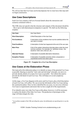
The Complete Use Case
Use Case Place Bet
Short Description: The user places a bet on a particular horse after choosing a race
Actors: Gambler
Requirements R2.3; R7.1
Pre-Conditions: The User has successfully logged in
Post-Conditions: A bet was placed and the bet was recorded by the system
Main Flow:
(1) On initiation of Place Bet by the gambler, a list of the day’s races are requested
from the system, and (2) the list of races are displayed
(3) The Gambler chooses the race to bet on [A1] and (4) the system presents a list of
the runners for that race
(5) The Gambler chooses the horse to bet on [A1] and enters the required stake [E1]
(6) The User Confirms the transaction and (7) the system displays a confirmation
message
Alternate Flow(s):
(A1) The gambler cancels the transaction.
Post Condition - No bets were placed
Exception Flow(s):
(E1) The user’s credit is not sufficient to fund the bet. The user is informed and the
Use Case Terminates
Figure 43 - Full Use Case Description
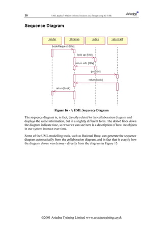
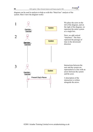
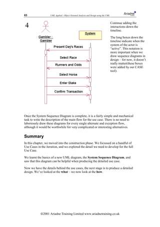
The UML Sequence Diagram
Producing the Use Case Descriptions is difficult. Many people find the distinction
between analysis and design especially difficult – often the Use Case descriptions
become littered with design decisions.
Here’s an example from the Place Bet Use Case:
“The User selects the race to bet on. The system interrogates the race database and
compiles an array of runners for the race.”
This is a poor Use Case description. By talking about the race database and
introducing arrays, we are tying ourselves down to specific design decisions.
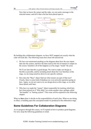
When building the Use Cases, we need to treat the system as a “black box”, which can
accept requests from actors and return results to the actor. We are not concerned (yet)
with how the black box fulfils that request.
We recommend the use of a UML Sequence Diagram. A sequence diagram is useful
in a variety of different situations, especially at the design stage. However, the
ã2001 Ariadne Training Limited www.ariadnetraining.co.uk](https://image.slidesharecdn.com/umlapplied-100901233853-phpapp01/85/UML-Applied-61-320.jpg)
![78 UML Applied - Object Oriented Analysis and Design using the UML
Chapter 14
Responsibility Assignment Patterns
In this section, we are going to take time out from the development process, and look
closely at the skills involved in building good Object Oriented Designs.
Some of the advice given in this chapter may appear to be quite obvious and trivial. In
fact, it is the violation of these simple guidelines that causes most of the problems in
object oriented design.
The GRASP Patterns
To improve the way in which we produce our collaboration diagrams, we’ll study the
so-called “GRASP” patterns, as described by Larman in reference [2].
What is a pattern?
A pattern is a well used, extremely general, solution to a common occurring problem.
The pattern movement began as an internet-based discussion community, but was
popularised through the classic textbook “Design Patterns” (reference 6), written by
the so called “Gang of Four”.
To aid communication, each design pattern has an easy to remember name (such as
Factory, Flywheel, Observer), and there are at least a handful of design patterns that
every self respecting designer should be familiar with.
We’ll be looking at some of the “Gang of Four’s” patterns later, but first we’ll study
the GRASP patterns.
GRASP stands for “General Responsibility Assignment Software Patterns”, and they
help us to ensure we allocate behaviour to classes in the most elegant way possible.
The patterns are called Expert, Creator, High Cohesion, Low Coupling and
Controller. Let’s look at them in turn:
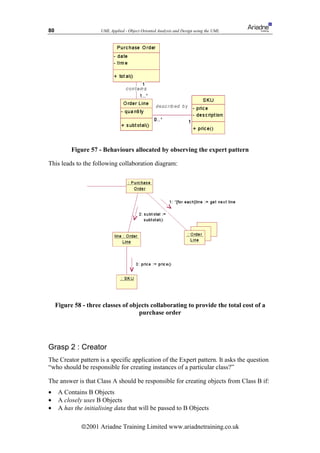
Grasp 1 : Expert
This is, on the face of it, a very simple pattern. It is also the one which is most
commonly broken! So, this pattern should be at the forefront of your mind whenever
you are building collaboration diagrams or creating design class diagrams.
Essentially, the Expert pattern says “given a behaviour, which class should the
behaviour be allocated to?”.
Wise allocation of behaviour leads to systems which are:
ã2001 Ariadne Training Limited www.ariadnetraining.co.uk](https://image.slidesharecdn.com/umlapplied-100901233853-phpapp01/85/UML-Applied-78-320.jpg)
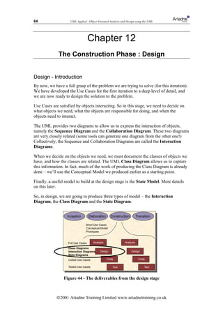
![107 UML Applied - Object Oriented Analysis and Design using the UML
The Construction Phase
The construction phase carries on as described in earlier chapters, but with each
subsystem being developed, iteratively, by separate teams, working in parallel and as
independently as possible.
At the end of each iteration, a phase of integration testing will take place, where the
interfaces across subsystems are tested.
Summary
This chapter looked at some of the issues surrounding large scale system
development. It is clear that although the UML is designed to be scaleable,
transferring the Iterative Incremental Framework to large projects is far from a simple
exercise.
The best approach at the moment seems to be the Architecture Centric approach
proposed by Rational Corp:
• Define subsystems from an early stage
• Keep complexity as manageable as possible
• Iterate in parallel but don’t hack interfaces
• Appoint a central architecture team
The package model provided by the UML provides a way of containing the large
complexity, and this model should be owned by the architecture team.
More reading : The Rational Website at www.rational.com provides several
interesting whitepapers on scalability issues such as multi-site working and systems
requiring multiple variants. In addition, reference [1] is an excellent introduction to
the Rational Unified Process and how the architecture centric approach can help
contain complexity.
ã2001 Ariadne Training Limited www.ariadnetraining.co.uk](https://image.slidesharecdn.com/umlapplied-100901233853-phpapp01/85/UML-Applied-107-320.jpg)

![123 UML Applied - Object Oriented Analysis and Design using the UML
Bibliography
[1] : Krutchten, Philippe. 2000 The Rational Unified Process An Introduction Second
Edition Addison-Wesley
A brief introduction to the Rational Unified Process, and its relationship with the UML
[2] : Larman, Craig. 1998 Applying UML and Patterns An Introduction to Object
Oriented Analysis and Design Prentice Hall
An excellent introduction to the UML, applied to real software development. Used as the basis for this
course.
[3] : Schmuller, Joseph. 1999 Teach Yourself UML in 24 Hours Sams
A surprisingly comprehensive introduction to UML, including details of the metamodel. The first half
concentrates on UML syntax, and the second half applies the UML (using a RUP-style process called
GRAPPLE)
[4] : Collins, Tony. 1998 Crash : Learning from the World’s Worst Computer
Disasters SimonSchuster
An entertaining collection of case studies exploring why so many software development projects fail
[5] : Kruchten, Phillipe 2000 From Waterfall to Iterative Lifecycle - a tough
transition for project managers Rational Software Whitepaper – www.rational.com
An excellent, and short, description of the problems project managers will face on an iterative project
[6] : Gamma, E., Helm, R., Johnson, R., Vlissides, J. 1995 Design Patterns : Elements
of Reusable Object Oriented Software Addison-Wesley
The classic “Gang of Four” catalogue of several design patterns
[7] : Riel, Arthur 1996 Object Oriented Design Heuristics Addison-Wesley
Rules of Thumb for Object Oriented Designers
[8] : UML Distilled
Martin Fowler's pragmatic approach to applying UML on real software developments
[9] : Kulak, D., Guiney, E. 2000 Use Cases : Requirements in Context Addison-
Wesley
An in depth treatment of requirement engineering, driven by Use Cases
ã2001 Ariadne Training Limited www.ariadnetraining.co.uk](https://image.slidesharecdn.com/umlapplied-100901233853-phpapp01/85/UML-Applied-123-320.jpg)

This document provides an overview and introduction to using the Unified Modeling Language (UML) for object-oriented analysis and design. It discusses the UML's role within common software development processes like the waterfall model and iterative frameworks. It also introduces basic UML diagram types and how they are used during the different phases of analysis and design such as use case modeling, conceptual modeling, analysis, and design. The document is intended as a course companion for learning to apply the UML in a development project.


![[DSBW Spring 2009] Unit 03: WebEng Process Models](https://cdn.slidesharecdn.com/ss_thumbnails/unit03-process-090328140932-phpapp02-thumbnail.jpg?width=640&height=640&fit=bounds)


