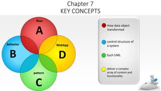
The document discusses various modeling techniques used in requirements analysis for web applications (WebApps), including:
1) Content modeling to identify and describe all content objects and their relationships.
2) Interaction modeling using use cases, sequence diagrams, state diagrams, and prototypes to describe how users interact.
3) Functional modeling to define all necessary operations and processing functions implied by usage scenarios.
The techniques help analysts understand WebApp requirements by modeling key elements like content, interactions, and functions.
3. Overiew
oAren’t those requirements modeling representations enough?
owhat is requirement modeling ?
owho dose it ?
owhy is important ?
owhat are the step ?
oWhat is the work product ?
oHow do I ensure that I’ve done it righ ?
4. • One view of requirements modeling, called structured analysis,
considers data and the processes that transform the data as separate
entities
• Data objects are modeled in a way that defines their attributes and
relationships.
• Processes that manipulate data objects are modeled in a manner that shows
how they transform data as data objects flow through the system.
• A second approach to analysis modeled, called objectoriented analysis,
focuses on
• the definition of classes and
• the manner in which they collaborate with one another to effect customer
requirements.
• what approach choose software team ?
5. oRepresents how data objects are transformed at they Represents how data
objects are transformed at they move through the system
ocan be used to complement UML diagrams and provide additional insight into
system requirements and flow.
odata flow diagram (DFD) is the diagrammatic form that is used
9. External Entity
o A producer or consumer of data
o Examples: a person, a device, a sensor
o Another example: computer-basedsystem
o Data must always originate some where
and must always be sent to something
10. Process
oA data transformer (changes input to output)
oExamples: compute taxes, determine
area,
oformat report, display graph
oData must always be processed in some
way to achieve system function
11. • Data flows through a system, beginningas
input and transformed into output.
Data Flow
compute
triangle
area
base
height
area
12. Data Stores
• Data is often stored for later use.
look-up
sensor
data
sensor #
report required
sensor #, type,
location, age
sensor data
sensor number
type,
location, age
15. Creating a Control Flow Model
oFor some types of applications, the data model and the data flow diagram
are all that is necessary to obtain meaningful insight into software
requirements.
olarge class of applications are “driven” by events rather than data
oproduce control information rather than reports or displays, and process
information with heavy concern for time and performance
oSuch applications require the use of control flow modelingin addition to
data flow modeling.
16. Creating a Control Flow Model .cont
event or control item
o To select potential candidate events, the following guidelines are suggested:
List all sensors that are “read” by the software.
List all interrupt conditions.
List all “switches” that are actuated by an operator.
List all data conditions.
Recalling the noun/verb parse that was applied to the processing narrative,
review all “control items” as possible control specification inputs/outputs.
Describe the behavior of a system by identifying its states, identify how each
state is reached, and define the transitions between states.
Focus on possible omissions—a very common error in specifying control; for
example, ask: “Is there any other way I can get to this state or exit from it?”
17. Control Specification
A control specification(CSPEC)
represents the behavior of the system
in tow way
oThe CSPEC contains a state diagram that
is a sequential specification of behavior.
oIt can also contain a program activation
table—a combinatorial specification of
behavior
oCSPEC can be:
o state diagram
o state transition table
o decision tables
o activation tables
for example:
Safe home
20. PAT
oA some what different mode of behavioral representation is the
process activation table
oThe PAT represents information contained in the state diagram in the
context of processes, not states
othe table indicates which processes (bubbles) in the flow model will
be invoked when an event occurs
ocan be used as a guide for a designer who must build an executive
that controls the processes represented at this level
21.
22. The Process Specification(PSPEC)
• used to describe all flow model processes that appear at the final level of
refinement
• narrative text
• program design language (PDL)
• mathematical equations
• tables, or UML activity diagrams.
• To illustrate the use of the PSPEC
• consider the process password transform represented in the flow model for
SafeHome
23. PSPEC: process password (at control panel)
The process password transform performs password validation at the control panel for the Safe
Home security function. Process password receives a four-digit password from the interact with user
function. The password is first compared to the master password stored within the system. If the
master password matches, <valid id message = true> is passed to the message and status display
function. If the master password does not match, the four digits are compared to a table of secondary
passwords (these may be assigned to house guests and/or workers who require entry to the home
when the owner is not present). If the password matches an entry within the table,<valid id message =
true> is passed to the message and status display function. If there is no match, <valid id message =
false> is passed to the message and status display function
24.
25. Overview
• The behavioral model indicates how software will respond to external
events or stimuli
• for create this model
• Evaluate all use cases to fully understand the sequence of interaction within
the system.
• Identify events that drive the interaction sequence and understand how these
events relate to specific objects.
• Create a sequence for each use case.
• Build a state diagram for the system.
• Review the behavioral model to verify accuracy and consistency.
26. Identifying Events With the Use Case
oIn general, an event occurs whenever the system and an actor
exchange information
oA use case is examined for points of information exchange. To
illustrate, we reconsider the use case for a portion of the SafeHome
security function.
oA use case is examined for points of information exchange
oAs an example of a typical event
homeowner uses the keypad to key in a four-digit password.
oafter recognize all event
27. State Representations
two different characterizations of states must be considered
1. the state of each class as the system performs its function
o passive
A passive state is simply the current status of all of an object’s attributes.
o active
The active state of an object indicates the current status of the object as it undergoes a
continuing transformation or processing.
2. the state of the system as observed from the outside as the system
performs its function
28. Two Different Behavior
State diagrams for
analysis classes.
indicates how an
individual class changes
state based on external
events
Sequence diagrams.
One component of a
behavioral model is a UML
state diagram9 that
represents active states for
each class and the events
(triggers) that cause
changes between these
active states
shows the behavior of
the software as a
function of time.
sequence diagram in
UML, indicates how
events cause transitions
from object to object
29. State Diagram for the ControlPanel Class
reading
locked
select ing
password
ent ered
comparing
password = incorrect
& numberOfTries < maxTries
password = correct
act iv at ion successful
key hit
do: validat ePassw ord
numberOfTries > maxTries
t imer < lockedTime
t imer > lockedTime
30. The States of a System
ostate—a set of observable circum-stances that characterizes the
behavior of a system at a given time
ostate transition—the movement from one state to another
oevent—an occurrence that causes the system to exhibit some
predictable form of behavior
oaction—process that occurs as a consequence of making a transition
31. Behavioral Modeling
• make a list of the different states of a system (How does the system
behave?)
• indicate how the system makes a transition from one state to another
(How does the system change state?)
• indicate event
• indicate action
• draw a state diagram or a sequence diagram
32. Sequence Diagram
homeowner cont rol panel sensorssyst em sensors
syst em
ready
reading
request lookup
comparing
result
password ent ered
password = correct
request act ivat ion
act ivat ion successful
locked
num berOf Tries > m axTries
select ing
t imer > lockedTime
A
A
Figure 8 .2 7 Sequence diagram (part ial) f or Saf eHome securit y f unct ion
act ivat ion successful
33.
34. Patterns for Requirements Modeling
o Software patterns are a mechanism for capturing domain knowledge in a way that allows
it to be reapplied when a new problem is encountered
domain knowledge can be applied to a new problem within the same application domain
the domain knowledge captured by a pattern can be applied by analogy to a completely
different application domain.
o The original author of an analysis pattern does not “create” the pattern, but rather,
discovers it as requirements engineering work is being conducted.
o Once the pattern has been discovered, it is documented
35. Discovering Analysis Patterns
oThe most basic element in the description of a requirements
model is the use case.
oA coherent set of use cases may serve as the basis for
discovering one or more analysis patterns.
oA semantic analysis pattern (SAP) “is a pattern that describes a
small set of coherent use cases that together describe a basic generic
application.”
36. An Example
o Consider the following
preliminary use case for
software required to control
and monitor a real-view
camera and proximity sensor
for an automobile:
o Use case: Monitor reverse motion
o Description: When the vehicle is placed in reverse
gear, the control software enables a video feed from
a rear-placed video camera to the dashboard display.
The control software superimposes a variety of
distance and orientation lines on the dashboard
display so that the vehicle operator can maintain
orientation as the vehicle moves in reverse. The
control software also monitors a proximity sensor to
determine whether an object is inside 10 feet of the
rear of the vehicle. It will automatically break the
vehicle if the proximity sensor indicates an object
within 3 feet of the rear of the vehicle.
37. Actuator-Sensor Pattern
o Pattern Name: Actuator-Sensor
o Intent: Specify various kinds of sensors and actuators in an embedded system.
o Motivation: Embedded systems usually have various kinds of sensors and actuators. These sensors
and actuators are all either directly or indirectly connected to a control unit. Although many of the
sensors and actuators look quite different, their behavior is similar enough to structure them into a
pattern. The pattern shows how to specify the sensors and actuators for a system, including
attributes and operations. The Actuator-Sensor pattern uses a pull mechanism (explicit request for
information) for PassiveSensors and a push mechanism (broadcast of information) for the
ActiveSensors.
o Constraints:
o Each passive sensor must have some method to read sensor input and attributes that represent the
sensor value.
o Each active sensor must have capabilities to broadcast update messages when its value changes.
o Each active sensor should send a life tick, a status message issued within a specified time frame, to
detect malfunctions.
o Each actuator must have some method to invoke the appropriate response determined by the
ComputingComponent.
o Each sensor and actuator should have a function implemented to check its own operation state.
o Each sensor and actuator should be able to test the validity of the values received or sent and set its
operation state if the values are outside of the specifications
38. Actuator-Sensor Pattern .cont
Applicability: Useful in any system in which multiple sensors
and actuators are present.
Structure: A UML class diagram for the Actuator-Sensor Pattern
is shown in Figure 7.8. Actuator, PassiveSensor and
ActiveSensor are abstract classes and denoted in italics. There
are four different types of sensors and actuators in this pattern.
The Boolean, integer, and real classes represent the most
common types of sensors and actuators. The complex classes
are sensors or actuators that use values that cannot be easily
represented in terms of primitive data types, such as a radar
device. Nonetheless, these devices should still inherit the
interface from the abstract classes since they should have basic
functionalities such as querying the operation states.
39. Actuator-Sensor Pattern .cont
Behavior: Figure 7.9 presents a UML sequence diagram for an
example of the Actuator-Sensor Pattern as it might be applied for
the Safe Home function that controls the positioning (e.g., pan,
zoom) of a security camera. Here, the Control Panel queries a
sensor (a passive position sensor) and an actuator (pan control)
to check the operation state for diagnostic purposes before reading
or setting a value. The messages Set Physical Value and Get
Physical Value are not messages between objects. Instead, they
describe the interaction between the physical devices of the
system and their software counterparts. In the lower part of the
diagram, below the horizontal line, the Position Sensor reports that
the operation state is zero. The Computing Component then
sends the error code for a position sensor failure to the Fault
Handler that will decide how this error affects the system and
what actions are required. it gets the data from the sensors and
computes the required response for the actuators.
40.
41. WebApps modeling
Content Analysis. The full spectrum of content to be provided by the WebApp is identified,
including text, graphics and images, video, and audio data. Data modeling can be used to
identify and describe each of the data objects.
Interaction Analysis. The manner in which the user interacts with the WebApp is described
in detail. Use-cases can be developed to provide detailed descriptions of this interaction.
Functional Analysis. The usage scenarios (use-cases) created as part of interaction analysis
define the operations that will be applied to WebApp content and imply other processing
functions. All operations and functions are described in detail.
Configuration Analysis. The environment and infrastructure in which the WebApp resides
are described in detail.
42. When Do We Perform Analysis?
• In some WebE situations, analysis and design merge. However, an
explicit analysis activity occurs when …
• the WebApp to be built is large and/or complex
• the number of stakeholders is large
• the number of Web engineers and other contributors is large
• the goals and objectives (determined during formulation) for the WebApp
will effect the business’ bottom line
• the success of the WebApp will have a strong bearing on the success of the
business
43. The Content Model
Content objects are extracted from use-cases
examine the scenario description for direct and indirect references to content
Attributes of each content object are identified
The relationships among content objects and/or the hierarchy of content maintained
by a WebApp
• Relationships—entity-relationship diagram or UML
• Hierarchy—data tree or UML
44. Data Tree
Figure 1 8 .3 Dat a t ree for aSafeHom e c om ponent
component
part Number
part Name
part Type
descript ion
price
Market ingDescript ion
Phot ograph
TechDescript ion
Schemat ic
Video
WholesalePrice
Ret ailPrice
45. The Interaction Model
Composed of four elements:
o use-cases
o sequence diagrams
o state diagrams
o a user interface prototype
Each of these is an important UML notation and is described in
Appendix I
46. Sequence Diagram
Figure 18.5 Sequence diagram f or use-case:select Saf eHome component s
new cust o mer
:Room :FloorPlan
d e sc ri b e s
ro o m *
p l a c e s ro o m
i n f l o o r p l a n
:Product
Component
se l e c t s p ro d u c t c o m p o n e n t *
:Billof
Mat erials
a d d t o Bo M
FloorPlan
Reposit ory
sa v e f l oo r p l a n c o n f i g u ra t i o n
sa v e b i l l o f m a t e ri a l s
BoM
Reposit ory
47. State Diagram
Figure 1 8 .6 Part ial st at e diagram f or ne w c us t om e rint eract ion
n e w cu st o m e r
Validat ing user
syst em st at us=“input ready”
displaymsg = “ent eruserid”
displaymsg =“ent erpswd”
ent ry/ log-in request ed
do: run user validat ion
exit / set user access swit ch
select “log-in”
userid
validat ed
password validat ed
Select ing user act ion
syst em st at us=“link ready”
display: navigat ion choices”
ent ry/ validat ed user
do: link as required
exit / user act ion select ed
select ot her f unct ions
select cust omizat ion f unct ionalit y
select e-commerce (purchase) f unct ionalit y
Cust omizing
syst em st at us=“input ready”
display: basic inst ruct ions
ent ry/ validat ed user
do: process user select ion
exit / cust omizat ion t erminat ed
select descript ive
cont ent
room being def ined
Def ining room
syst em st at us=“input ready”
display: roomdef . window
ent ry/ roomdef . select ed
do: run room queries
do: st ore room variables
exit / room complet ed
select descript ive
cont ent
Building f loor plan
syst em st at us=“input ready”
display: f loor plan window
ent ry/ f loor plan select ed
do: insert room in place
do: st ore f loor plan variables
exit / room insert ion complet ed
select descript ive
cont ent
select ent er room in f loor plan
Saving f loor plan
syst em st at us=“input ready”
display: st orage indicat or
ent ry/ f loor plan save select ed
do: st ore f loor plan
exit / save complet ed
select save f loor plan
room insert ion complet ed
next select ion
cust omizat ion complet e
all rooms
def ined
48. The Functional Model
The functional model addresses two processing elements of the WebApp
o user observable functionality that is delivered by the WebApp to end-users
o the operations contained within analysis classes that implement behaviors associated
with the class.
An activity diagram can be used to represent processing flow
49. Activity Diagram
Figur e 1 8 .7 Act ivit y diagr am f or c o m p u t e Pr i c e( ) o p e r a t i o n
init ialize t ot alCost
invoke
calcShipping Cost
g et price and
quant it y
c omponent s remain onBoMList
invoke
det ermineDiscount
disc ount < = 0
disc ount >0
t ot alCost=
t ot alCost - discount
t axTot al=
t ot alCost x t axrat e
no c omponent s remain onBoMList
lineCost =
price x quant it y
add lineCost t o
t ot alCost
priceTot al =
t ot alCost + t axTot al
+ shipping Cost
ret urns:
shipping Cost
ret urns: discount
50. The Configuration Model
Server-side
oServer hardware and operating system environment must be specified
oInteroperability considerations on the server-side must be considered
oAppropriate interfaces, communication protocols and related collaborative
information must be specified
Client-side
oBrowser configuration issues must be identified
oTesting requirements should be defined
51. Navigation Modeling-I
Should certain elements be easier to reach (require fewer navigation steps) than
others? What is the priority for presentation?
Should certain elements be emphasized to force users to navigate in their direction?
How should navigation errors be handled?
Should navigation to related groups of elements be given priority over navigation to a
specific element.
Should navigation be accomplished via links, via search-based access, or by some
other means?
Should certain elements be presented to users based on the context of previous
navigation actions?
Should a navigation log be maintained for users?
52. Navigation Modeling-II
o Should a full navigation map or menu (as opposed to a single “back” link or directed
pointer) be available at every point in a user’s interaction?
o Should navigation design be driven by the most commonly expected user behaviors or
by the perceived importance of the defined WebApp elements?
o Can a user “store” his previous navigation through the WebApp to expedite future
usage?
o For which user category should optimal navigation be designed?
o How should links external to the WebApp be handled? overlaying the existing browser
window? as a new browser window? as a separate frame?