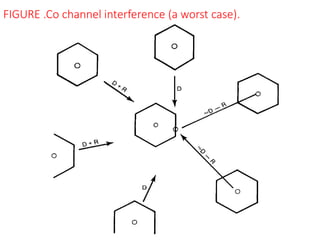
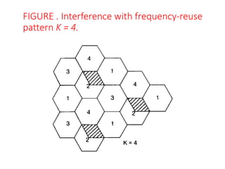
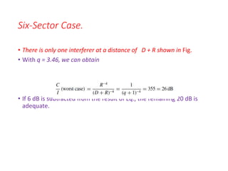
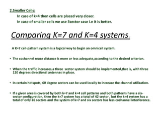
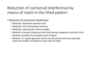
1. The document discusses co-channel interference which occurs when the same frequency is reused in different cell locations. It describes how directional antennas and increasing the number of sectors can reduce this interference.
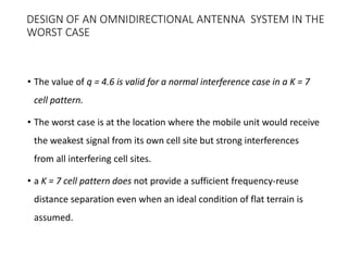
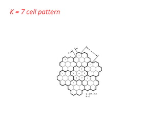
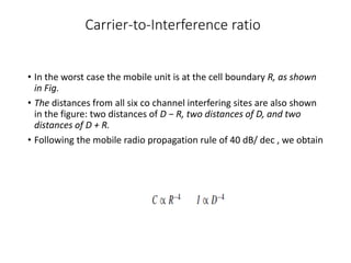
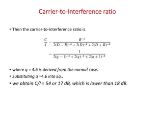
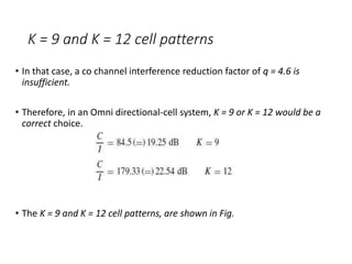
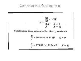
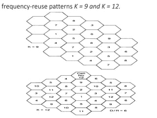
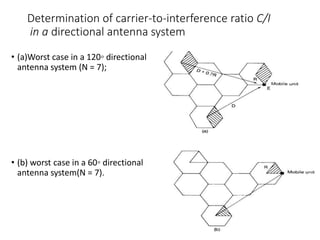
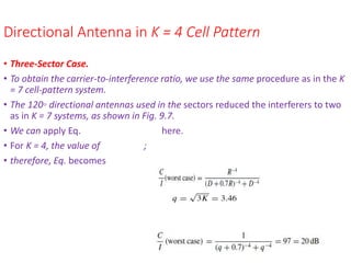
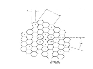
2. Methods to calculate the carrier-to-interference ratio in different scenarios are presented, including for omni-directional antennas with different frequency reuse patterns and for directional antenna systems.
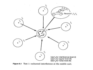
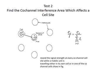
3. Determining the co-channel interference area involves measuring signal levels with a mobile receiver and comparing to thresholds for carrier-to-interference and carrier-to-noise ratios.
Cellular networks address the problems of spectral congestion and limited user capacity by replacing single high-power transmitters with many low-power transmitters. This allows for frequency reuse, where the same frequencies can be used in cells farther apart due to lower transmission powers. Key aspects of cellular networks include frequency reuse patterns, cell types and sizes, co-channel interference management through techniques like sectorization and microcell deployment, and balancing capacity gains from smaller cells and frequency reuse against infrastructure costs. Cellular networks provide major improvements in spectral efficiency and user capacity over traditional wireless networks.
This document discusses advanced wireless communication technologies and their evolution over time to meet increasing data rate demands. It covers:
1) How wireless spectrum has become crowded as usage has increased, challenging engineers to develop technologies to achieve higher data rates within limited spectrum.
2) The evolution of mobile communication standards from 1G analog to 2G digital systems like GSM, and then 3G technologies like UMTS that supported data rates up to 384kbps.
3) Emerging 4G technologies aimed to support rates over 20Mbps using techniques like MIMO, adaptive modulation, and OFDM to more efficiently use available spectrum.
1) The document discusses parameters used to characterize mobile multipath channels including power delay profile, mean excess delay, RMS delay spread, maximum excess delay, coherence bandwidth, Doppler spread, and coherence time.
2) These parameters are derived from the power delay profile and describe aspects of the channel such as time dispersion, frequency selectivity, and time variation due to Doppler shift.
3) Examples of typical values for different channel parameters are given for outdoor and indoor mobile radio channels.
The key characteristic of a cellular network is the ability to reuse frequencies to increase both coverage and capacity. Cellular networks divide geographic areas into smaller cells and assign different frequency groups to neighboring cells to minimize interference and allow for frequency reuse. This allows the same frequencies to be reused in different cells separated by a sufficient distance.
Capacity planning(CP) determines operational expenditure, capital expenditure and long-term performance of the system hence it is the most important phase in the life cycle of a cellular system. For the past three decades, capacity planning problems have studied for all generations of the cellular system. So, to increase the capacity of the network in future we focus on small cells of cell structure. Cellular network includes the variety of different cell sizes and types, heterogeneous networks, control, and data plane split architectures, coordinated multipoint, massive multiple inputs multiple outputs.
The objective of this presentation is to focus on traditional deployment reviews and identify future opportunities, challenges, and trends in detail. More specifically we investigate the future capacity planning by reviewing the CP process including its objective input and output parameter to an optimization process and the CP phases.
The document discusses key concepts in GSM cellular networks including:
1. An overview of GSM including its definition, phases, specifications, system architecture, network areas, and advantages over analog systems.
2. Cell planning principles such as types of cells, the planning process, and cell clusters.
3. Frequency reuse which allows frequencies to be reused in different cells to improve capacity, with an example shown.
Interference limits the capacity of cellular radio systems by creating bottlenecks that reduce performance. The two primary types of interference are co-channel interference, which occurs between cells using the same frequencies, and adjacent channel interference, which occurs between nearby frequency channels. Managing interference is important for cellular system design in order to minimize cross-talk and missed/blocked calls.
This document discusses the concept of diffraction as it relates to wireless communication. It explains that diffraction allows radio signals to propagate behind obstacles between a transmitter and receiver. It presents Huygen's principle, which states that each point on a wavefront can be considered a secondary source of wavelets. These wavelets combine to form a new wavefront. The document also covers knife-edge diffraction geometry and how to calculate the excess path length and phase difference between the diffracted and direct paths. It defines Fresnel zones and introduces the Fresnel zone diffraction parameter used to determine whether interference will be constructive or destructive. Additionally, it explains diffraction loss that occurs when secondary waves are blocked, resulting in only partial energy being diffract
Smith chart:A graphical representation.amitmeghanani
The document discusses the Smith chart, which is a graphical tool used to solve transmission line problems. Some key points:
- The Smith chart was developed in 1939 and allows tedious transmission line calculations to be done graphically.
- It provides a mapping between the normalized impedance plane and the reflection coefficient plane. Circles of constant resistance and reactance are plotted, along with the reflection coefficient.
- Parameters like impedance, admittance, reflection coefficient, VSWR can all be plotted and derived from locations on the chart.
- Examples are given of using the Smith chart to determine input impedance, reflection coefficient, and stub matching of transmission lines with various termination impedances.
GENERAL DESCRIPTION OF THE PROBLEM , CONCEPT OF FREQUENCY CHANNELS, CO-CHANNEL iNTERFERENCE REDUCTION FACTOR , DESIRED C/I FROM A NORMAL CASE IN A OMNI DIRECTIONAL ANTENNA SYSTEM , CELL SPLITTING , CONSIDERATION OF THE COMPONENTS OF CELLULAR SYSTEM.
This power point presentation discusses cell splitting and sectoring techniques used to increase channel capacity in cellular networks. It explains that a large cellular area is divided into smaller hexagonal cells, each with its own base station and frequency set. To further increase capacity, cells can be split into smaller cells served by additional base stations. Alternatively, directional antennas can be used to sector each cell into three segments to reduce interference and allow frequency reuse over smaller areas. Both techniques aim to add channels by subdividing congested cells.
Introduction to Cellular Mobile System,
Performance criteria,
uniqueness of mobile radio environment,
operation of cellular systems,
Hexagonal shaped cells,
Analog Cellular systems.
Digital Cellular systems
This document provides an overview of cellular network generations from 1G to 4G. It discusses the evolution from analog 1G networks to digital 2G networks with TDMA and CDMA. 2.5G networks brought higher data rates with technologies like GPRS. 3G networks enabled broadband data and voice over IP. 4G aims to further increase data throughput through advanced technologies like OFDMA and MC-CDMA. The document compares key technologies like GSM and CDMA, and discusses cellular standards, network architectures, applications and the transition from older to newer generations.
Wireless cellular networks divide geographic areas into cells served by base stations to allow for frequency reuse. As users travel between cells, their calls are handed off seamlessly. Cellular systems improve capacity by allocating unique frequency groups to each cell and reusing the same frequencies in cells sufficiently distant from each other. Larger networks connect multiple base stations and mobile switching centers to facilitate roaming and complete calls between mobile and fixed users.
Spread spectrum modulation is a wideband modulation technique that provides three main advantages over fixed frequency transmission: resistance to noise/interference, difficulty intercepting signals, and allowing multiple transmissions to efficiently share frequencies. There are two types of spread spectrum systems: averaging systems like direct sequence modulation that spread signals; and avoidance systems like frequency hopping that rapidly change frequencies. Pseudo-noise codes with certain properties are used to spread and despread direct sequence signals. Hybrid spread spectrum systems combine techniques to gain advantages while reducing disadvantages.
Massive MIMO (also known as “Large-Scale Antenna Systems”, “Very Large MIMO”, “Hyper MIMO”, “Full-Dimension MIMO” and “ARGOS”) makes a clean break with current practice through the use of a large excess of service-antennas over active terminals and time division duplex operation. Extra antennas help by focusing energy into ever-smaller regions of space to bring huge improvements in throughput and radiated energy efficiency. Other benefits of massive MIMO include the extensive use of inexpensive low-power components, reduced latency, simplification of the media access control (MAC) layer, and robustness to intentional jamming. The anticipated throughput depend on the propagation environment providing asymptotically orthogonal channels to the terminals, but so far experiments have not disclosed any limitations in this regard. While massive MIMO renders many traditional research problems irrelevant, it uncovers entirely new problems that urgently need attention: the challenge of making many low-cost low-precision components that work effectively together, acquisition and synchronization for newly-joined terminals, the exploitation of extra degrees of freedom provided by the excess of service-antennas, reducing internal power consumption to achieve total energy efficiency reductions, and finding new deployment scenarios.
This document summarizes the telecommunication network of MTNL (Mahanagar Telephone Nigam Limited), India's state-owned telecom service provider in Mumbai and Delhi. It discusses the key components of MTNL's network including telephone exchanges, main distribution frames, switching systems, and various exchanges used. It also provides an overview of MTNL's broadband services, describing the requirements for broadband connections such as ADSL modems, and the network model for ADSL. The document contains diagrams illustrating the main parts of the telecommunication network and the network model for ADSL.
Deterministic MIMO Channel Capacity
• CSI is Known to the Transmitter Side
• CSI is Not Available at the Transmitter Side
Channel Capacity of Random MIMO Channels
2.6 cellular concepts - frequency reusing, channel assignmentJAIGANESH SEKAR
- Cellular networks address the problem of limited spectrum availability by using frequency reuse, where nearby base stations are assigned different channels to avoid interference. Cells are arranged in a hexagonal pattern and the same set of channels are reused in cells sufficiently far from each other.
- There are two main channel assignment strategies - fixed assignment, where each cell has a predetermined set of channels, and dynamic assignment, where channels are allocated on demand by a central controller considering interference levels. Dynamic assignment helps improve spectrum utilization but requires more complex coordination.
- Frequency reuse allows the available spectrum to be reused as needed across multiple cells as long as interference is kept at acceptable levels, increasing network capacity.
cellular concepts in wireless communicationasadkhan1327
The document discusses the concept of frequency reuse in cellular networks. It explains that a limited radio spectrum is used to serve millions of subscribers by dividing the network coverage area into cells and reusing frequencies across spatially separated cells. Each cell is allocated a portion of the total available frequencies, and neighboring cells are assigned different frequencies to minimize interference. The frequency reuse factor is defined as the ratio of the minimum distance between co-channel cells to the cell radius. Larger frequency reuse factors provide better isolation between co-channel cells but reduce network capacity. The document also covers additional topics like different channel assignment strategies, handoff methods, interference calculation and optimization of frequency reuse networks.
Multiple Input Multiple Output (MIMO) technology uses multiple antennas at both the transmitter and receiver to improve channel robustness and throughput. By utilizing reflected signals, MIMO can provide gains in channel robustness and throughput. MIMO was initially developed in the 1990s after additional processing power made it possible to utilize both spatial diversity and spatial multiplexing. MIMO systems provide either spatial multiplexing gain to maximize transmission rate or diversity gain to minimize errors and prioritize reliability. MIMO is now used in many wireless communication standards and ongoing research aims to develop more advanced MIMO techniques.
Wireless communication involves transmitting information such as voice and data through electromagnetic waves without wires. It allows for flexible and mobile connectivity between devices. The document discusses various topics related to wireless communication including point-to-point communication, multiuser systems, modulation techniques, channel models and capacity. It provides an overview of the evolution of wireless technologies and applications.
This document discusses multiple-input multiple-output (MIMO) systems, including their motivations and capabilities. MIMO systems use multiple antennas at both the transmitter and receiver to achieve high data rates approaching 1 Gbps while maintaining quality of service. The document covers MIMO channel models and capacity, design criteria like diversity and spatial multiplexing, practical architectures like V-BLAST and Alamouti's scheme, and applications to networking including MIMO-OFDM and MIMO MAC protocols.
This document is a thesis submitted by Mohammed Abuibaid to Kocaeli University regarding adaptive beam-forming. It discusses various beam-forming techniques including switched array antennas, DSP-based phase manipulation, and beamforming by precoding. It also covers adaptive beamforming algorithms such as LMS, NLMS, RLS, and CM. Various beam patterns generated by these algorithms are presented. The document motivates the need for adaptive beamforming and 3D beamforming to improve energy efficiency in wireless networks.
Cellular networks employ frequency reuse to increase capacity by assigning different frequency channels to adjacent cells to avoid interference. Due to co-channel interference, the same frequency cannot be used in adjacent cells and frequencies assigned to different cells must be separated by distances large enough to keep interference levels low. The objective of frequency reuse is to reuse frequencies in nearby cells by assigning different frequencies to adjacent cells using a frequency reuse plan and cluster size.
This document contains 10 questions related to cellular network design and analysis. The questions cover topics such as: calculating the reuse ratio of a hexagonal cell geometry; determining the optimal cluster size based on signal interference ratios; calculating cell radii based on interference thresholds; estimating call blocking probabilities; describing aspects of the AMPS cellular standard; calculating path loss and received power over distance for different propagation models; analyzing diffraction effects; and estimating the percentage of time a desired SNR is achieved over distance.
This document discusses key concepts in cellular networks including frequency reuse, channel assignment strategies, interference reduction techniques, and methods for improving capacity. It introduces frequency reuse where the same channels are used in different cells separated by sufficient distance. Channel assignment strategies include fixed and dynamic assignment. Sources of interference like co-channel and adjacent channel are described along with methods to calculate signal-to-interference ratio. Improving capacity is discussed through cell splitting and sectoring.
Cellular systems use multiple low-power transmitters (base stations) rather than a single, high-power transmitter to increase capacity and coverage. Frequency reuse is used to allocate channels to nearby base stations to minimize interference. Handoff strategies are employed to transfer calls between base stations as users move. Interference and power control techniques aim to equalize signal power levels and improve capacity. Traffic engineering principles including Erlang formulas are applied to determine the optimal number of channels needed based on expected call volumes.
The document provides an introduction to cellular concepts. Key points include:
1) Cellular networks divide a service area into smaller sections called cells to allow for frequency reuse and serve more subscribers. Each cell has a base station with a limited number of radio channels.
2) The same set of radio frequencies can be reused in cells separated by a sufficient distance to avoid co-channel interference exceeding acceptable levels.
3) Factors like terrain, buildings, and mobility affect signal propagation and can cause fading, interference, and frequency shifts. Techniques like sectoring cells and using directional antennas help mitigate these issues and improve frequency reuse.
Cellular networks face two major types of interference: co-channel interference and adjacent channel interference. Co-channel interference occurs between cells using the same frequency, while adjacent channel interference is caused by signals leaking into nearby frequency bands from imperfect receiver filters. To reduce interference, cellular systems employ frequency reuse by allocating frequencies to distant cells, careful channel assignment to separate adjacent channels, and cell splitting to increase capacity by dividing cells. The frequency reuse factor and worst-case signal-to-interference ratio must be considered in the design to ensure sufficient voice quality.
1) Frequency reuse in cellular networks results in co-channel interference from signals using the same frequency band but located in different cells.
2) Under normal conditions, co-channel signals do not interfere due to being located outside the cell boundary. However, troposcattering and transmission power issues can cause co-channel interference.
3) Measuring the carrier-to-interference ratio and carrier-to-noise ratio can help quantify co-channel interference levels. Frequency reuse increases spectrum efficiency but also co-channel interference, so reduction techniques are important.
This document discusses several key considerations for path loss and signal propagation in mobile environments:
1) Path loss increases with the fourth power of distance rather than the square law in fixed wireless, and antenna gain improvements are lower due to extensive multipath effects from vehicles and buildings.
2) Cellular systems operate at higher frequencies than earlier mobile systems, resulting in smaller antennas and greater path loss. Fades occur more frequently as the mobile unit moves in and out of constructive and destructive interference areas.
3) Techniques like sectorization, cell splitting, increased transmit power, frequency/space diversity, and CDMA help to mitigate fading and maximize coverage and capacity in mobile wireless networks.
This document provides an overview of key cellular coverage concepts including cell splitting, channel grouping, carrier to interference ratios, tower distance to cell radius ratios, and cellular network architecture. It explains how these concepts are used to efficiently provide cellular coverage and maximize channel capacity.
Cellular Concepts by Mian Shehzad Iqbal,
Earlier systems used single high power
transmitter. So no frequency reuse
• Cellular concept solve the problem of spectral
congestion and user capacity without any major
technological changes.
• Replaces single high power transmitter with
many low power transmitters.
• Each base station is allocated portion of
available channels.
• Distribution to neighbors so that minimize
interference.
Hexagonal shape is only logical shape.
Actual coverage of cell is known as
footprint and is determined by
measurements and prediction models.
Cell must be designed to serve the
weakest mobile at edge in footprint.
MSC plays major role by monitoring reuse
distance, cost function and other issues. • MSC
needs to collect real time data on channel
occupancy, traffic distribution and radio signal
strength indications (RSSI) this increases the
storage and computational load but provides the
advantage of increased channel utilization and
decreased probability of blocked calls.
The document discusses cellular network architecture and interference. It describes how cellular networks divide geographic coverage areas into hexagonal cells serviced by low-power base stations to reuse frequencies and increase capacity. Interference between cells using the same frequency is a major limiting factor and can be reduced by increasing the distance between co-channel cells. The document also discusses types of interference like co-channel and adjacent channel interference and techniques to mitigate interference like increasing cluster size and implementing power control.
03. Chapter- Three Elements of Cellular Radio System Design1.pdfsamiulsuman
The document summarizes key elements of cellular radio system design including low power transmitters, frequency reuse, co-channel interference reduction, handoff mechanisms, and cell splitting. It discusses how frequency reuse allows the same channels to be used in different cells to increase capacity but can cause co-channel interference. Handoff mechanisms allow calls to be transferred between cells as users move. Cell splitting involves installing new base stations to reduce interference and increase capacity in busy areas.
The document discusses frequency planning in GSM networks. Key topics covered include defining the task of frequency planning as assigning carriers to cells to minimize interference and maximize capacity. Methods of frequency assignment and reuse are described, including reuse patterns and factors that impact co-channel interference like cluster size. Simulation results show that larger cluster sizes and sectorized sites achieve higher probabilities of acceptable carrier-to-interference ratios. Fading margins must be considered due to the effect of fading on both desired and interfering signals.
The cellular concept divides a large service area into smaller cells served by low-power base stations to improve capacity and spectrum reuse. Each base station is allocated a group of radio channels for its cell. Areas are divided into hexagonal cells served by a central base station to allow frequencies to be reused efficiently while minimizing interference between adjacent cells. Handoff allows calls to be transferred between base stations as users move between cells to maintain call quality.
1) Cellular networks divide a region into smaller areas called cells to improve capacity and reuse frequencies. Each cell contains a base station that can communicate with user equipment within its coverage area.
2) Frequency reuse allows the same set of frequencies to be reused in different cells by ensuring sufficient distance between cells using the same frequencies. This increases overall network capacity.
3) Handoff allows calls to be transferred between base stations as users move between cells to maintain call quality. Various handoff strategies aim to minimize call drops during handoffs.
A Channel Sharing Scheme for Cellular Mobile Communications.pdfTracy Morgan
This summarizes a document describing a new channel sharing scheme called Neighbor Cell Channel Sharing (NCCS) for cellular networks. NCCS partitions each cell into an inner and outer region. Channels are divided into nominal channels for exclusive cell use and sharing channels that can be used in a cell's inner region and its neighbors' inner regions. When a cell's nominal channels are full, it can borrow sharing channels from neighbors to serve calls in its inner region, or swap channels with inner region calls to serve outer region calls. This allows traffic-adaptive channel assignment without channel locking.
The document discusses the cellular concept in wireless networks. Key points include:
- Cells have a hexagonal shape and neighboring cells reuse frequencies to avoid interference and increase capacity.
- Frequency reuse allows more simultaneous calls by allocating the same set of frequencies to different neighboring cells.
- Cell size is a tradeoff between interference and system capacity - smaller cells mean lower power needs but more cells and handoffs.
This document discusses various types of antennas used in cellular networks including:
- Omnidirectional antennas used for initial coverage which provide uniform coverage in all directions.
- Directional antennas used to reduce co-channel interference with beamwidths of 120° or 60°.
- Diversity antennas separated horizontally at cell sites to reduce fading through combination of signals.
- Umbrella pattern antennas used to control energy within a confined area through top-loading monopoles or discone designs.
- Minimum separation of receiving antennas is required to reduce pattern ripples affecting performance of space diversity.
- Roof mounted mobile antennas provide near uniform patterns while glass mounted antennas have lower gains.
This presentation provides an overview of the cellular concept and key related topics:
- Cells are small geographical service areas defined by a base station and radio channels. Multiple cells are grouped into clusters to fully utilize available frequencies through frequency reuse.
- Handoff is the process of transferring voice and control signals between cells as a mobile moves between cells during a call. Successful and infrequent handoffs are important.
- Interference is reduced through frequency reuse and strategies like cell splitting and sectoring. Cell splitting divides cells into smaller areas served by low-power base stations to increase channel reuse and capacity. Sectoring uses directional antennas to reduce interference from co-channel cells.
The document discusses key concepts in cellular system design including frequency reuse, cell size, system capacity, and handoff strategies. The cellular concept allows efficient reuse of a fixed number of channels across a large coverage area by dividing the area into smaller cells and reusing frequencies in cells sufficiently distant from each other to prevent interference. System capacity is determined by the number of available channels, cluster size which impacts frequency reuse distance and interference levels, and the number of times a cluster can be replicated across the coverage area. Handoff strategies aim to transfer calls seamlessly between cells as users move and involve monitoring signal levels, assigning priority to handoffs over new calls, and reserving guard channels.
This document discusses key concepts in cellular systems including frequency reuse, interference management, and capacity improvement techniques. The main points are:
1. Cells reuse radio frequencies to allow large numbers of users by allocating different frequency groups to neighboring cells. This reduces interference within tolerable limits.
2. Interference is managed through techniques like frequency planning, channel assignment strategies, and power control. The balance of interference and capacity is important.
3. System capacity can be improved through cell splitting, sectoring cells with directional antennas, using different cell sizes, and coverage zone techniques. Managing interference is crucial to improving cellular network capacity.
The document discusses key concepts in cellular network design including:
- Frequency reuse which involves dividing a service area into cells and assigning different channel groups to adjacent cells to allow channels to be reused.
- Channel assignment strategies including fixed assignment where channels are permanently assigned to cells and dynamic assignment where channels are allocated on demand.
- Handoff strategies for transferring calls between cells as users move, including techniques like guard channels and queuing handoff requests.
- Interference, which is the major limiting factor for capacity, including co-channel interference between cells using the same frequencies and adjacent channel interference from nearby frequencies.
The document discusses key concepts in cellular network design including:
- Frequency reuse which allows the same channels to be reused in different cells by assigning different channel groups to adjacent cells to minimize interference.
- Channel assignment strategies including fixed assignment where channels are permanently assigned to cells and dynamic assignment where channels are allocated on demand considering interference.
- Handoff strategies to transfer calls between cells as users move, prioritizing ongoing calls through guard channels and queuing handoff requests.
- Interference, particularly co-channel interference between cells using the same channels, which is the major limiting factor in capacity and requires sufficient separation between co-channel cells. Signal-to-interference ratio characterizes this interference.
An Experimental mmWave Channel Model for UAV to UAV Communication.pdfSambasiva62
This paper proposes an empirical propagation loss model for UAV-to-UAV communications at 60 GHz based on extensive measurement data collected from aerial experiments using Facebook Terragraph channel sounders mounted on DJI M600 drones. The measurement results validate the empirical path loss model and show that path loss does not have an explicit dependence on UAV height between 6-15 meters. The paper also compares the proposed model to 3GPP channel models and publicly releases the measurement dataset.
This document describes an IOT-based vehicle accident and alcohol detection system using GSM and GPS. The system aims to (1) track the location of an accident using GPS and send messages to emergency services and family, and (2) detect if the driver has consumed alcohol using an alcohol sensor and prevent the vehicle from moving if so, sending an alert to police. It consists of an ARM7 microcontroller interfaced with a GPS module, GSM module, MQ3 alcohol sensor and accelerometer. If an accident occurs, the location is sent via GSM. If alcohol is detected, the vehicle is stopped and police alerted. The system aims to reduce accidents and response time to save lives.
The document summarizes various communication bands and their uses. The L-band from 1-2 GHz is used for radar, satellite communications, GPS signals, and weather systems. It has a low bandwidth but can penetrate clouds and weather. The S-band from 2-4 GHz is mainly used for radar systems and two-way communications for devices. It provides accurate radar data but can be affected by rain. The C-band from 4-8 GHz is used for satellite communications between ground stations and has less interference from rain than higher frequencies. It supports distribution of TV, mobile services, and disaster recovery.
This document discusses frequency management and channel assignment in cellular networks. It explains that frequency management divides available channels into subsets that can be assigned to each cell, either fixed or dynamically. It describes how channels are divided and grouped in the Advanced Mobile Phone System (AMPS). Channels can be assigned to cell sites on a long-term fixed basis or short-term dynamic basis. The document also discusses set-up channels, voice channels, frequency reuse patterns, and techniques for channel sharing, borrowing, and sectorization to improve spectrum efficiency and traffic capacity.
The document discusses various multiple access techniques used in wireless communication systems to allow multiple users to access a shared radio channel simultaneously. It describes Frequency Division Multiple Access (FDMA), Time Division Multiple Access (TDMA), Code Division Multiple Access (CDMA), and Space Division Multiple Access (SDMA). FDMA divides the bandwidth into different frequency channels. TDMA divides the time dimension into different time slots. CDMA uses unique codes to identify users within the same frequency band. SDMA enables spatial separation of users within the same frequency and time. The document provides details on the principles, advantages, and disadvantages of each multiple access technique.
The document discusses mobile radio propagation models. It begins by describing the free space propagation model, which predicts received signal strength between a transmitter and receiver with line of sight. It then discusses how distance, transmitted power, antenna gains, wavelength and losses impact received power based on Friis transmission equation. Later it introduces the ground reflection model, knife edge diffraction model and scattering model to account for common propagation mechanisms. It concludes by discussing how path loss models like log-distance and log-normal shadowing can be used for link budget design and outdoor propagation modeling.
This document discusses design technologies for improving productivity in embedded systems design. It focuses on automation through synthesis, reuse through intellectual property cores, and verification through hardware/software co-simulation. Synthesis is described as automatically converting a system's behavioral description into a structural implementation to optimize design metrics. Logic synthesis, register-transfer synthesis, and behavioral synthesis are discussed as techniques that operate at different levels of abstraction in the design process.
A channel model is a mathematical representation of how a communication channel affects wireless signals. There are four categories of channel models: path loss models which represent signal power reduction over distance without filtering; purely stochastic models which address noise and multipath fading without geometry; spatial models which were developed for MIMO systems to account for antenna arrays; and ray tracing models which use location information to explicitly define scatterers. Channel models are essential for predicting link and system performance and reduce the need for costly measurement projects.
The document discusses integrated circuit (IC) design technology. It covers IC technology types including full-custom, semicustom, and programmable logic devices. It also discusses design technology topics such as automation through synthesis, verification through hardware/software co-simulation, and reuse through intellectual property cores. The document provides details on the IC design process and challenges associated with increasing design complexity.
This document describes the design of custom single-purpose processors. It discusses converting algorithms to state machines and finite state machines with datapaths. It also covers creating the datapath and controller, including registers, functional units, multiplexors and the controller state table and implementation. The example shown is for a greatest common divisor processor.
This document provides an overview of 5G technology, including its evolution from previous generations of wireless technology. 5G is expected to offer speeds up to 1 Gbps, make wireless networks globally accessible at low cost, and support applications like wearable devices with AI capabilities. The architecture of 5G is designed as an open platform across different layers, including an Open Wireless Architecture for the physical and data link layers and an Open Transport Protocol for the transport and session layers. 5G aims to create a true wireless world with virtually no limitations on access or coverage areas.
This document discusses microprocessor interfacing and communication. It covers topics such as basic communication protocols using address, data and control buses. It describes different interfacing techniques like memory-mapped I/O, port-based I/O, and interrupt-driven I/O. Interrupts allow a peripheral to asynchronously signal the processor to service an event. The processor saves its state and jumps to a fixed or vectored interrupt service routine location to handle the interrupt before returning to the main program.
This document discusses various standard single-purpose processors including timers, counters, watchdog timers, UARTs, LCD controllers, stepper motor controllers, analog-to-digital converters, and real-time clocks. It provides details on the functionality and applications of these common peripherals, as well as examples of their basic configurations and implementations.
This document introduces embedded systems and their design challenges. It defines embedded systems as computing systems embedded within electronic devices that are single-functioned, tightly-constrained, and reactive in real-time. The key design challenge is optimizing numerous metrics like cost, size, performance, and time-to-market simultaneously. It also outlines common processor, integrated circuit, and design technologies used for embedded systems.
The document provides an overview of embedded systems including:
- Embedded systems are computing systems embedded within electronic devices like cameras, cell phones, and appliances.
- Designing embedded systems involves optimizing multiple metrics like cost, power usage, performance, and time to market. Improving one metric may negatively impact others.
- Time to market is an important metric as delays in releasing a product can result in significant lost revenues by missing the peak sales window.
KuberTENes Birthday Bash Guadalajara - K8sGPT first impressionsVictor Morales
K8sGPT is a tool that analyzes and diagnoses Kubernetes clusters. This presentation was used to share the requirements and dependencies to deploy K8sGPT in a local environment.
Harnessing WebAssembly for Real-time Stateless Streaming PipelinesChristina Lin
Traditionally, dealing with real-time data pipelines has involved significant overhead, even for straightforward tasks like data transformation or masking. However, in this talk, we’ll venture into the dynamic realm of WebAssembly (WASM) and discover how it can revolutionize the creation of stateless streaming pipelines within a Kafka (Redpanda) broker. These pipelines are adept at managing low-latency, high-data-volume scenarios.
Using recycled concrete aggregates (RCA) for pavements is crucial to achieving sustainability. Implementing RCA for new pavement can minimize carbon footprint, conserve natural resources, reduce harmful emissions, and lower life cycle costs. Compared to natural aggregate (NA), RCA pavement has fewer comprehensive studies and sustainability assessments.
Presentation of IEEE Slovenia CIS (Computational Intelligence Society) Chapte...University of Maribor
Slides from talk presenting:
Aleš Zamuda: Presentation of IEEE Slovenia CIS (Computational Intelligence Society) Chapter and Networking.
Presentation at IcETRAN 2024 session:
"Inter-Society Networking Panel GRSS/MTT-S/CIS
Panel Session: Promoting Connection and Cooperation"
IEEE Slovenia GRSS
IEEE Serbia and Montenegro MTT-S
IEEE Slovenia CIS
11TH INTERNATIONAL CONFERENCE ON ELECTRICAL, ELECTRONIC AND COMPUTING ENGINEERING
3-6 June 2024, Niš, Serbia
A review on techniques and modelling methodologies used for checking electrom...nooriasukmaningtyas
The proper function of the integrated circuit (IC) in an inhibiting electromagnetic environment has always been a serious concern throughout the decades of revolution in the world of electronics, from disjunct devices to today’s integrated circuit technology, where billions of transistors are combined on a single chip. The automotive industry and smart vehicles in particular, are confronting design issues such as being prone to electromagnetic interference (EMI). Electronic control devices calculate incorrect outputs because of EMI and sensors give misleading values which can prove fatal in case of automotives. In this paper, the authors have non exhaustively tried to review research work concerned with the investigation of EMI in ICs and prediction of this EMI using various modelling methodologies and measurement setups.
Literature Review Basics and Understanding Reference Management.pptxDr Ramhari Poudyal
Three-day training on academic research focuses on analytical tools at United Technical College, supported by the University Grant Commission, Nepal. 24-26 May 2024
ACEP Magazine edition 4th launched on 05.06.2024Rahul
This document provides information about the third edition of the magazine "Sthapatya" published by the Association of Civil Engineers (Practicing) Aurangabad. It includes messages from current and past presidents of ACEP, memories and photos from past ACEP events, information on life time achievement awards given by ACEP, and a technical article on concrete maintenance, repairs and strengthening. The document highlights activities of ACEP and provides a technical educational article for members.
DEEP LEARNING FOR SMART GRID INTRUSION DETECTION: A HYBRID CNN-LSTM-BASED MODELgerogepatton
As digital technology becomes more deeply embedded in power systems, protecting the communication
networks of Smart Grids (SG) has emerged as a critical concern. Distributed Network Protocol 3 (DNP3)
represents a multi-tiered application layer protocol extensively utilized in Supervisory Control and Data
Acquisition (SCADA)-based smart grids to facilitate real-time data gathering and control functionalities.
Robust Intrusion Detection Systems (IDS) are necessary for early threat detection and mitigation because
of the interconnection of these networks, which makes them vulnerable to a variety of cyberattacks. To
solve this issue, this paper develops a hybrid Deep Learning (DL) model specifically designed for intrusion
detection in smart grids. The proposed approach is a combination of the Convolutional Neural Network
(CNN) and the Long-Short-Term Memory algorithms (LSTM). We employed a recent intrusion detection
dataset (DNP3), which focuses on unauthorized commands and Denial of Service (DoS) cyberattacks, to
train and test our model. The results of our experiments show that our CNN-LSTM method is much better
at finding smart grid intrusions than other deep learning algorithms used for classification. In addition,
our proposed approach improves accuracy, precision, recall, and F1 score, achieving a high detection
accuracy rate of 99.50%.
CHINA’S GEO-ECONOMIC OUTREACH IN CENTRAL ASIAN COUNTRIES AND FUTURE PROSPECTjpsjournal1
The rivalry between prominent international actors for dominance over Central Asia's hydrocarbon
reserves and the ancient silk trade route, along with China's diplomatic endeavours in the area, has been
referred to as the "New Great Game." This research centres on the power struggle, considering
geopolitical, geostrategic, and geoeconomic variables. Topics including trade, political hegemony, oil
politics, and conventional and nontraditional security are all explored and explained by the researcher.
Using Mackinder's Heartland, Spykman Rimland, and Hegemonic Stability theories, examines China's role
in Central Asia. This study adheres to the empirical epistemological method and has taken care of
objectivity. This study analyze primary and secondary research documents critically to elaborate role of
china’s geo economic outreach in central Asian countries and its future prospect. China is thriving in trade,
pipeline politics, and winning states, according to this study, thanks to important instruments like the
Shanghai Cooperation Organisation and the Belt and Road Economic Initiative. According to this study,
China is seeing significant success in commerce, pipeline politics, and gaining influence on other
governments. This success may be attributed to the effective utilisation of key tools such as the Shanghai
Cooperation Organisation and the Belt and Road Economic Initiative.
Advanced control scheme of doubly fed induction generator for wind turbine us...IJECEIAES
This paper describes a speed control device for generating electrical energy on an electricity network based on the doubly fed induction generator (DFIG) used for wind power conversion systems. At first, a double-fed induction generator model was constructed. A control law is formulated to govern the flow of energy between the stator of a DFIG and the energy network using three types of controllers: proportional integral (PI), sliding mode controller (SMC) and second order sliding mode controller (SOSMC). Their different results in terms of power reference tracking, reaction to unexpected speed fluctuations, sensitivity to perturbations, and resilience against machine parameter alterations are compared. MATLAB/Simulink was used to conduct the simulations for the preceding study. Multiple simulations have shown very satisfying results, and the investigations demonstrate the efficacy and power-enhancing capabilities of the suggested control system.
2. CO-CHANNEL INTERFERENCE
• Introduction To Co-channel Interference
• Procedure to Find Nearest Neighbours of a Particular Cell
• Co-channel Interference Reduction Factor
• Desired C/Ifrom a Normal and Worst case in an Omni-
directional Antenna
• Impact on Co-channel Interference by Lowering the Antenna
Hight
3. NON CO-CHANNEL INTERFERENCE
•Adjacent Channel Interference
•Near End To Far End Interference
•Interference Between Systems
•Long Distance Interference
•Uhf Tv Interference
4. Interference: A process in which two or more waves are super-
imposed in such a way that they produce higher peaks, lower
troughs, or a new wave pattern.
In other word, it is the effect when the two or more waves overlap
or intersect with each other, and the amplitude of the resulting
wave depends upon the frequencies and phases of the individual
waves.
Co-channel Interference: The interference between the signals
from the co-channel cells is called the co-channel interference.
Adjacent channel Interference: The interference between the
signals from the adjacent channel cell is called the adjacent
channel interference.
5. Major Limiting Factor For Cellular System Performance Is
The Interference
Interferences can cause:
Cross Talk
Missed And Blocked Calls.
Sources Of Interference?
Another mobile in the same cell (if distance & frequency are
close)
A call-in progress in neighboring cell (if frequency is close).
Other base stations operating in the same frequency band (from
co-channel cells)
Non-cellular systems leaking energy into cellular frequency band
6. Cochannel Interference
• The Frequency-reuse Method Is Useful For Increasing The Efficiency Of
Spectrum Usage But Results In Co Channel Interference Because The
Same Frequency Channel Is Used Repeatedly In Different Co Channel
Cells.
Co-channel Cells Cells That Share Same Set Of
Frequencies
• The Co Channel Interference Reduction Factor Q = 4.6 Is Based On The
System Required C/I = 18 Db Of The AMPS System.
7. Introduction to Co-Channel Interference
• The co channel interference is usually involved with FDMA,
TDMA, and OFDMA systems.
• The interference occurred because the frequency reuse
scheme is applied to those systems in which the channels
operate at the same frequency but repeatedly in separate
locations.
8. COCHANNEL INTERFERENCE
• In most mobile radio environments, use of a seven-cell reuse pattern is not
sufficient to avoid co channel interference for AMPS systems.
• Increasing K > 7 would reduce the number of co channels per cell, and that
would also reduce spectrum efficiency.
• Therefore, it might be advisable to retain the same number of radios as the
seven-cell system but to sector the cell radially, as if slicing a pie.
• This technique would reduce co channel interference and use channel
sharing and channel borrowing schemes to increase spectrum efficiency.
9. Determination of Co-channel Interference Area
• For detection of serious co channel interference in areas in a cellular system
a test is conducted.
• Test: Find the co channel interference area from a mobile receiver.
• While performing this test we watch for any change detected by a field
strength recorder in mobile unit and compare the data with the condition of
no co channel interference.
• This test must be repeated as the mobile unit travels in every co channel
cell.
• To facilitate the test, we can install a channel scanning receiver in one car.
10. • One channel f1 records the signal level and another channel f2 records
the interference level while the third channel f3 is used to record only
the noise level.
• We can obtain ,in decibels, the carrier to interference ratio C/I by
subtracting the result obtained from f2 from the result obtained from f1.
• We can also obtain the carrier to noise ratio C/N by subtracting the
result obtained from f3 from the result obtained from f1.
• Four conditions should be used to compare the results:
11.
12. • If the carrier- to- Interference ratio C/I is greater than 18 dB through out
the cell, the system is properly designed.
• If C/I is less than 18 dB and C/N is greater than 18 dB in some areas,
there is no co channel interference.
• If both C/I and C/N are less than 18dB and C/N=C/I in a given area there
is a coverage problem.
• 4. If both C/I and C/N are less than 18dB and C/N>C/I in a given area
there is a coverage problem and co channel interference.
13. record the signal strength at every co channel cell
site while a mobile unit is
travelling either in its own cell or in one of the co
channel cells show in fig.
14. DESIGN OF AN OMNIDIRECTIONAL ANTENNA SYSTEM IN THE
WORST CASE
• The value of q = 4.6 is valid for a normal interference case in a K = 7
cell pattern.
• The worst case is at the location where the mobile unit would receive
the weakest signal from its own cell site but strong interferences
from all interfering cell sites.
• a K = 7 cell pattern does not provide a sufficient frequency-reuse
distance separation even when an ideal condition of flat terrain is
assumed.
16. Carrier-to-Interference ratio
• In the worst case the mobile unit is at the cell boundary R, as shown
in Fig.
• The distances from all six co channel interfering sites are also shown
in the figure: two distances of D − R, two distances of D, and two
distances of D + R.
• Following the mobile radio propagation rule of 40 dB/ dec , we obtain
18. • Then the carrier-to-interference ratio is
• where q = 4.6 is derived from the normal case.
• Substituting q =4.6 into Eq.,
• we obtain C/I = 54 or 17 dB, which is lower than 18 dB.
19. K = 9 and K = 12 cell patterns
• In that case, a co channel interference reduction factor of q = 4.6 is
insufficient.
• Therefore, in an Omni directional-cell system, K = 9 or K = 12 would be a
correct choice.
• The K = 9 and K = 12 cell patterns, are shown in Fig.
22. Determination of carrier-to-interference ratio C/I
in a directional antenna system
• (a)Worst case in a 120◦ directional
antenna system (N = 7);
• (b) worst case in a 60◦ directional
antenna system(N = 7).
23. Directional Antennas In K = 7 Cell Patterns
• Three-Sector Case: The three-sector case is shown in Fig.
• To illustrate the worst-case situation, two co-channel cells are shown in Fig. a.
• The mobile unit at position E will experience greater interference in the lower
shaded cell sector than in the upper shaded cell-sector site.
• This is because the mobile receiver receives the weakest signal from its own
cell but fairly strong interference from the interfering cell.
24. Directional Antennas In K = 7 Cell Patterns
• Because of the use of directional antennas, the number of principal
interferers is reduced from six to two (Fig. 9.5).
• The worst case of C/I occurs when the mobile unit is at position E, at
which point the distance between the mobile unit and the two
interfering antennas is roughly D +(R/2);
• C/I can be calculated more precisely as follows.
25. Directional Antennas In K = 7 Cell Patterns
• The value of C/I can be obtained by the following expression (assuming that
the worst case is at position E at which the distances from two interferers
are D + 0.7 and D).
• Let q = 4.6; then Eq. becomes
26. • The C/I received by a mobile unit from the 120◦ directional antenna
sector system expressed in Eq.
greatly exceeds 18 dB in a worst case.
• Equation shows that using directional antenna sectors can improve the
signal-to-interference ratio, that is, reduce the co channel interference.
• However, in reality, the C/I could be 6 dB weaker than in Eq. in a heavy
traffic area as a result of irregular terrain contour and imperfect site
locations.
• The remaining 18.5 dB is still adequate.
27. Six-Sector Case.
• We may also divide a cell into six sectors by using six 60◦-beam directional
antennas as shown in Fig. b.
• In this case, only one instance of interference can occur in each sector as shown
in Fig. 9.5.
• Therefore, the carrier-to-interference ratio in this case is
• For q = 4.6, Eq. becomes
• which shows a further reduction of co channel interference.
28. Directional Antenna in K = 4 Cell Pattern
• Three-Sector Case.
• To obtain the carrier-to-interference ratio, we use the same procedure as in the K
= 7 cell-pattern system.
• The 120◦ directional antennas used in the sectors reduced the interferers to two
as in K = 7 systems, as shown in Fig. 9.7.
• We can apply Eq. here.
• For K = 4, the value of ;
• therefore, Eq. becomes
30. Six-Sector Case.
• There is only one interferer at a distance of D + R shown in Fig.
• With q = 3.46, we can obtain
• If 6 dB is subtracted from the result of Eq., the remaining 20 dB is
adequate.
31. 2.Smaller Cells:
In case of k=4 then cells are placed very closer.
In case of smaller cells we use 3sector case i.e it is better.
Comparing K=7 and K=4 systems:
A K=7 cell-pattern system is a logical way to begin an omnicell system.
• The cochannel reuse distance is more or less adequate,according to the desired criterion.
• When the traffic increases,a three sector system should be implemented,that is, with three
120 degrees directional antennas in place.
• In certain hotspots, 60 degree sectors can be used locally to increase the channel utilization.
• If a given area is covered by both k=7 and k=4 cell patterns and both patterns have a six-
sector configuration, then the k=7 system has a total of 42 sector , but the k=4 system has a
total of only 26 sectors and the system of k=7 and six sectors has less cochannel interference.
32. Antenna Parameters and their effects
• LOWERING THE ANTENNA HEIGHT:
• Lowering the antenna height does not always reduce the co channel interference.
• In some circumstances, such as on fairly flat ground or in a valley situation,
lowering the antenna height will be very effective for reducing the co channel and
adjacent-channel interference.
33. On a High Hill or a High Spot
• The effective antenna height, rather than the actual height, is always
considered in the system design.
• Therefore, the effective antenna height varies according to the location of
the mobile unit.
• When the antenna site is on a hill, as shown in Fig. a, the effective antenna
height is h1 + H.
35. On a High Hill or a High Spot
• If we reduce the actual antenna height to 0.5h1, the effective antenna
height becomes 0.5h1 + H.
• The reduction in gain resulting from the height reduction is
36. On a High Hill or a High Spot
• If h1 << H, then Eq. becomes
• This simply proves that lowering antenna height on the hill does not
reduce the received power at either the cell site or the mobile unit.
37. In a Valley
• The effective antenna height as seen from the mobile unit shown in Fig.
b is he1, which is less than the actual antenna height h1.
• If he1 = 2/3 h1 and the new antenna height is lowered to ½ h1, then the
new effective antenna height, is
• Then the antenna gain is reduced by
39. In a Valley
• This simply proves that the lowered antenna height in a valley is very
effective in reducing the radiated power in a distant high elevation area.
• However, in the area adjacent to the cell-site antenna, the effective antenna
height is the same as the actual antenna height.
• The power reduction caused by decreasing antenna height by half is only
40. In a Forested Area
• In a forested area, the antenna should clear the tops of any trees in the
vicinity, especially when they are very close to the antenna.
• In this case, decreasing the height of the antenna would not be the
proper procedure for reducing co channel interference
• because excessive attenuation of the desired signal would occur in the
vicinity of the antenna and in its cell boundary if the antenna were
below the treetop level.
41. Reduction of cochannel interference by
means of notch in the tilted pattern
• Reduction of cochannel interference
• Method1:-Separation between cells
• Method2:-Use of directional antennas
• Method3:-Lowering the antenna height
• Method 1 increases frequency cells and channels assigned to cell sites is less
• Method 3 weakens the reception level of signal
• Method 2 is a good approach which uses directional antennas especially
when the number of frequency reuse cells are fixed.
42. • Installation of 120 degree directional antenna can reduce the
interference in the system by eliminating the radiation to the rest of its
240 degree sector.
• However, cochannel interference can exist even when a directional
antenna is used.
• With the separation of D=4.6R in 120 degree directional antenna, the
area of interference at the interference receiving cell is illuminated by
central angle 19 degree sector of the entire 120 degree transmitting
antenna pattern of serving cell.
43.
44. • Therefore attempts should be made to reduce the signal strength signal
strength of the interference in this 19 degree sector.
• There are two ways to tilt down the antenna patterns: i) Electronically ii)
Mechanically
• The electronic down tilting is to change the phases among the elements
of a colinear array antenna.
• Mechanical down tilting is to down tilt the antenna physically.
• To achieve a significant gain of C/I in the interference receiving cell, we
should consider using a notch in the center of the antenna pattern at the
interfering cell.
45. • An antenna pattern with a notch can be obtained by tilting the high gain
directional antenna mechanically downward.
46. Umbrella pattern
• It achieved by use of staggered discone antenna
• It is used only in omnidirectional case
• Benefits
• Energy is confined to immediate area of antenna
• Used to control both cochannel and long distance interference
• Hilly terrain consists of more holes, where umbrella pattern is more effective
• Frequency reuse distance can be shortened
• We can increase the antenna height and still decrease the cochannel
interference for umbrella patterns. But for normal antenna patterns we cannot
raise the antenna high enough to cover the weak signal spots.
47. Use of parasitic elements
• It create desired pattern in certain directions
• A drive antenna and single parasite can be combined in several ways
48. • A single parasite spaced one-quarter wavelength from drive antenna and
two parasites spaced one half wavelength from driven antenna are
shown in above fig.
• The radiation patterns are such that as shown in above figure because
the current flow in the parasite is much weaker than that in the drive
antenna.
• The combination of figures a and b gives the parabola dish which is
shown in fig c
• This is an effective arrangement for cell-site directional antennas with
non-wind-resistant structure which is a four element structure with one
active element.
50. • The above three cases are studied as follows
• The two elements are placed as close as 0.04λ.
• In the first case the lengths of the two elements are identical and
separated by 0.04λ. At the close spacing, the current flow in the parasite
is very strong. The two elements form a null along Y-axis in the
horizontal plane and z-axis in the vertical plane. The directive gain of 3
dB is obtained.
51. • In the second case the length of the parasite is 5 percent longer than
that of active one and separated by 0.04λ. In this case parasite acts as
reflector. The patterns are shown for both horizontal and vertical planes.
The directive gain of 6 dB is obtained.
• In the third case the length of the parasite is shorter than that of active
one and separated by 0.04λ. In this case parasite acts as director. The
patterns are shown for both horizontal and vertical planes. The directive
gain of 8 dB is obtained.
53. Voice quality
• Voice quality often cannot be measured by objective parameters
such as
• carrier-to-noise ratio C/N,
• the carrier-to-interference ratio C/I
• The baseband signal to noise ratio S/N
• the signal to noise and distortion ratio (SINAD).
Multi path fading plus variable vehicular speed are major factors for
deterioration of voice quality.
54. Following methods can correct imbalance
• Received carrier level be high to increase the signal level.
• Receiver sensitivity be high to lower the noise level.
• Maintain Low distortion level in the receiver to increase SINAD.
• Use a Diversity receiver to reduce the fading.
• Use a Good system design in mobile radio environment and good
adjacent-channel rejection to reduce the interference.
55. Subjective test
• Subjective test can be set up according to the criterion that 75% of
customers perceive the voice quality at a given C/N as being good
or excellent.
• CM4, CM5 the top two levels among the five circuit-merit (CM)
grades.
• The simulator of this test must be adjusted for different mobile
speeds.
56. Objective test
There are many objective tests at the baseband for both voice and data.
• The characterization of voice quality is very difficult, but evaluation of data
transmission is easy.
• There are two major terms: bit-error rates and word error rates.
• The bit-error rate (BER) is the first-order statistic (independent of time or vehicle
speed), and
• the word-error rate (WER) is the second-order statistic, which is affected by the
vehicle speed.
57. SINAD measurement
• SINAD has been Used as a measurement of communication signal
quality at the baseband or in the cellular mobile receiver to measure
the effective FM receiver sensitivity.
• SINAD = total output power/ non signal portion
= signal +noise + distortion/noise + distortion
58. Types of Non Co-channel
Interference
ADJACENT-CHANNEL INTERFERENCE
59. “Adjacent-channel interference”
•Interference from channels that are adjacent in
frequency is called adjacent channel interference.
•The primary reason for that is Imperfect Receive
Filters which cause the adjacent channel energy to
leak into your spectrum
• “Adjacent-channel interference” is a broad term.
• It includes next-channel (the channel next to the operating channel)
interference and neighboring-channel (more than one channel away
from the operating channel) interference.
• Adjacent-channel interference can be reduced by the frequency
assignment.
60. Next-Channel Interference
• Next-channel interference in an AMPS system affecting a particular mobile unit
cannot be caused by transmitters in the common cell site but must originate at
several other cell sites.
• This is because any channel combiner at the cell site must combine the selected
channels, normally 21 channels (630 kHz) away, or at least 8 or 10 channels away
from the desired one.
• Therefore, next-channel interference will arrive at the mobile unit from other cell
sites if the system is not designed properly.
62. next-channel interference
• The methods for reducing this next-channel interference use the receiving end.
• The channel filter characteristics are a 6 dB/oct slope in the voice band and a 24
dB/oct falloff outside the voice-band region (see Fig.).
• If the next-channel signal is stronger than 24 dB, it will interfere with the
desired signal.
• The filter with a sharp falloff slope can help to reduce all the adjacent-channel
interference, including the next-channel interference.
63. Neighboring-Channel Interference
• The channels that are several channels away from the next channel will cause
interference with the desired signal.
• Usually, a fixed set of serving channels is assigned to each cell site.
• If all the channels are simultaneously transmitted at one cell-site antenna, a
sufficient amount of band isolation between channels is required for a
multichannel combiner to reduce inter modulation products.
• Can be reduced if we use multiple antennas
64. NEAR-END–FAR-END INTERFERENCE
•In one cell: Because motor vehicles in a given cell are usually moving,
some mobile units are close to the cell site and some are not.
• The close-in mobile unit has a strong signal that causes adjacent channel
interference (see Fig. a).
• In this situation, near-end–far-end interference can occur only at the reception
point in the cell site.
• If a separation of 5B (five channel bandwidths) is needed for two adjacent
channels in a cell in order to avoid the near-end–far-end interference, it is then
implied that a minimum separation of 5B is required between each adjacent
channel used with one cell.
66. NEAR-END–FAR-END INTERFERENCE
• In Cells of Two Systems:
• Adjacent-channel interference can occur between two systems in a duopoly-
market system.
• In this situation, adjacent-channel interference can occur at both the cell site and
the mobile unit.
• For instance, mobile unit A can be located at the boundary of its own home cell A
in system A but very close to cell B of system B as shown in Fig b.
• The other situation would occur if mobile unit B were at the boundary of cell B of
system B but very close to cell A of system A.
67. In Cells of Two Systems:
• Following the definition of near-end–far-end interference, the solid
arrow indicates that interference may occur at cell site A and
• The dotted arrow indicates that interference may occur at mobile
unit A.
• Of course, the same interference will be introduced at cell site B and
mobile unit B.
68. EFFECT ON NEAR-END MOBILE UNITS
• Avoidance of Near-End–Far-End Interference:
• The near-end mobile units are the mobile units that are located very close to the
cell site.
• These mobile units transmit with the same power as the mobile units that are far
away from the cell site.
• The situation described below is illustrated in Fig.
• The distance d0 between a calling mobile transmitter and a base-station receiver
is much larger than the distance dI between a mobile transmitter causing
interference and the same base-station receiver.
70. EFFECT ON NEAR-END MOBILE UNITS
• Therefore, the transmitter of the mobile unit causing interference is close
enough to override the desired base-station signal.
• This interference, which is based on the distance ratio, can be expressed as
where γ is the path-loss slope.
• The ratio dI /d0 is the near-end–far-end ratio.
• From Eq. the effect of the near-end–far-end ratio on the carrier–adjacent-
channel interference ratio is dependent on the relative positions of the moving
mobile units.
71. Interference Between Systems
• In One city:
• Let us assume that there are two systems operating in one city. If a
mobile unit of system A is closer to the cell site of system B (fig a) while
a call is being initiated through system A, adjacent channel interference
can be produced if the transmitted frequency of the mobile unit A is
close to the covered band of preamplifier at cell site B.
• Due to this, the signals from mobile unit A will then leak into the
receiving channel of system B and cross talk will occur.
72.
73. • In adjacent cities:
• Two systems operating at the same frequency band and in the two
adjacent cities may interfere with each other if they do not coordinate
their frequency channel use.
• Most cases of interferences are due to cell sites at high altitudes shown
in below figure
74. • In start up systems a high altitude cell site is always attractive which
covers a larger area.
• How ever if the neighboring city also uses the same system, then the
result is a strong interference which can be avoided by the following
methods:
• 1. The frequencies used in one city should not be used in the adjacent
city. This arrangement is useful for two low capacity systems.
• 2. If both systems are high capacity, then decrease in the antenna height
will reduces the interference.
• 3. Directional antennas can be used.
75. Long Distance Interference
• Overwater path:
• This phenomenon is mentioned below
• 1. A 41-mi overwater path operating at 1.5 GHz in Massachusetts Bay,
because of low ducts, steady signal well above normal level is
received and because of high ducts, a high signal level is received
with deep fading.
• 2. A 275-mi overwater path operating at 812 and 857 MHz between
Charleston, South Carolina and Daytona beach, Florida.
76. • Federal Express Engineers have discovered that mobile unit in
Charleston with in 1-2 mi of shore line are capable of clear
communication with a repeater station in Daytona Beach.
• The same situation applies when the mobile unit is in Daytona Beach.
• Overland Path:
• Tropospheric scattering over a land path is not as persistent as that over
water and can be varied from time to time. Usually Tropospheric
propagation is more pronounced in morning and distance can be about
200-mi.
77. UHF TV interference
• Two types of interference can occur between UHF television and
850‐MHz cellular mobile phones.
• 1.Interference to UHF TV Receivers from Cellular Mobile Transmitters
• 2.Interference of Cellular Mobile Receivers by UHF TV Transmitters
• Interference to UHF TV Receivers from Cellular Mobile Transmitters:
• Frequency separation is wide and the power levels used by the UHF TV
broadcast transmitters, the likelihood of interference from cellular
phone transmission affecting broadcasting is very small.
• It can interfere when cell site transmission is 90MHz above TV channel.
• Some UHF channels overlap cellular mobile channels
78. • It can interfere under only two conditions
• 1. Band region with overlapping frequencies
• 2. Image interference region:- TV receiver or cellular receiver can receive two
transmitted signals, one from TV and one from cellular transmitter produce
intermodulation product which falls within the TV or mobile receive band
•Interference between TV and cellular mobile channels is
illustrated in Fig
79. • Interference of Cellular Mobile Receivers by UHF TV Transmitters:
• When a mobile receiver approaches a TV transmitter, it is easy to find
that transmission from the TV station will not interfere with the
reception at the mobile receiver.
• When the cell-site receiver is only 1 mi or less away from the TV station,
interference may result. However when the cell site is very close to the
TV station, the interference decreases as a result of the two vertical
narrow beams pointing at different elevation levels. For this reason it is
advisable to mount a cell-site antenna in the same vicinity as the TV
station antenna if the problems of shielding and grounding can be
controlled.