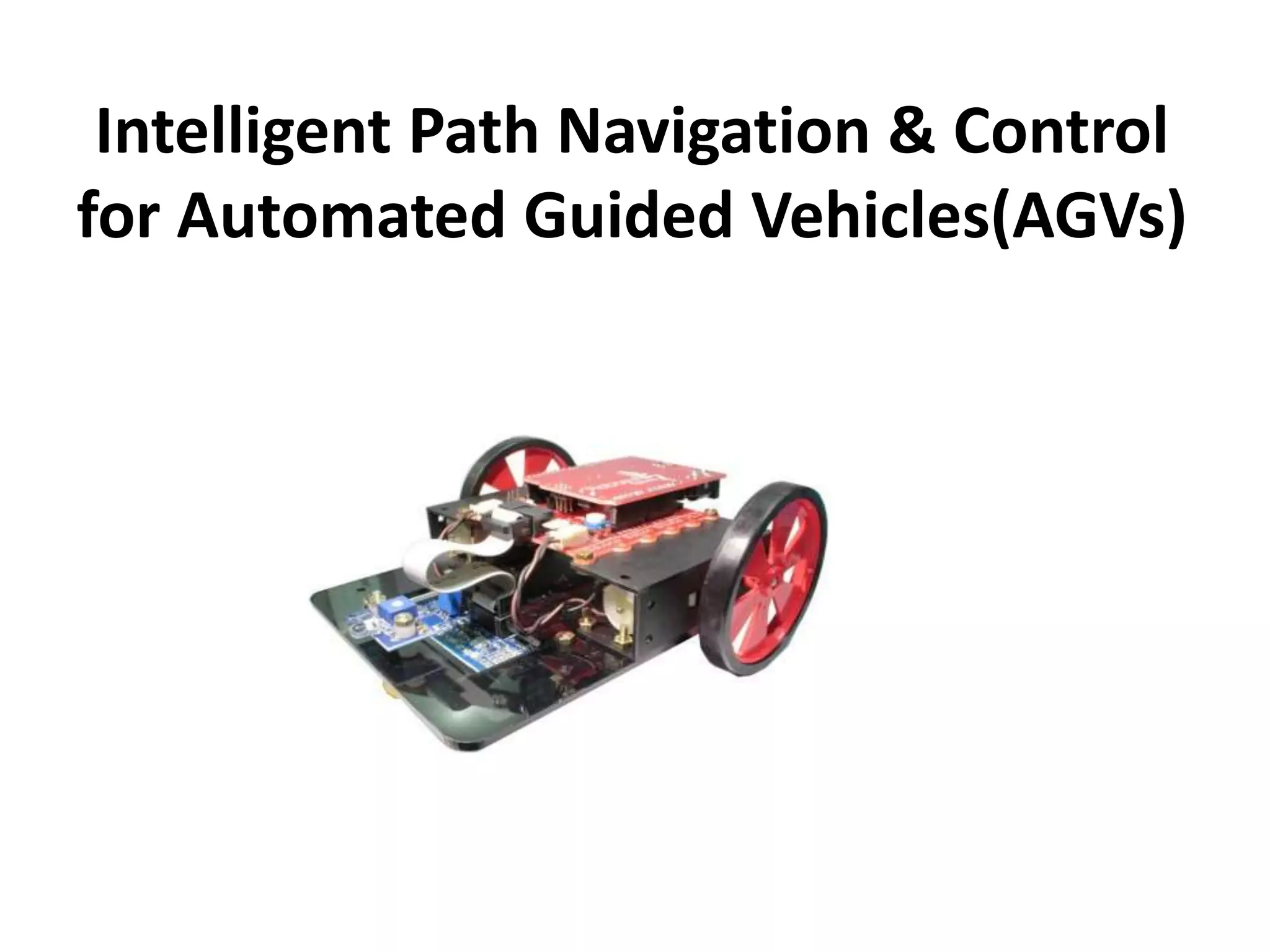
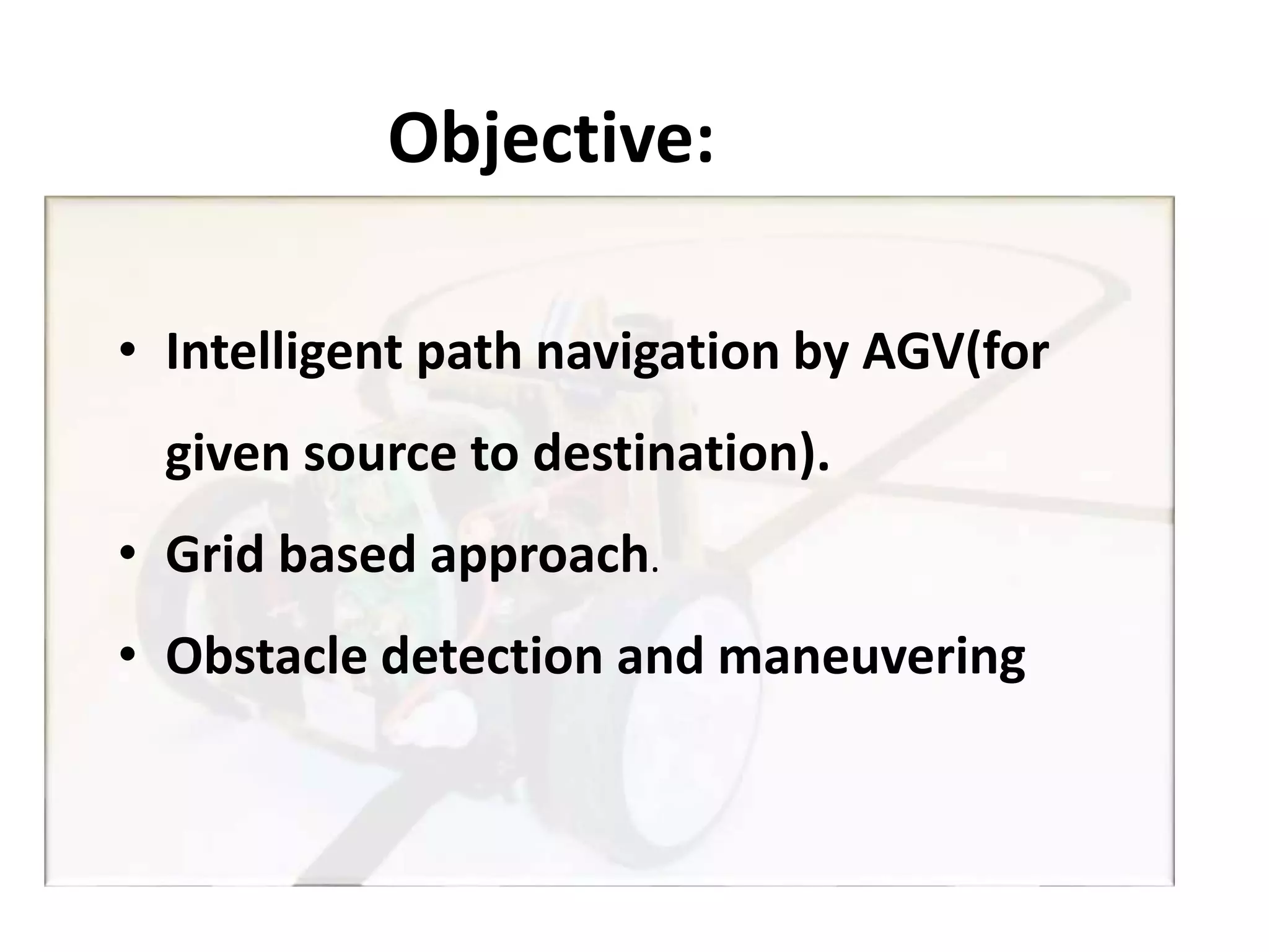
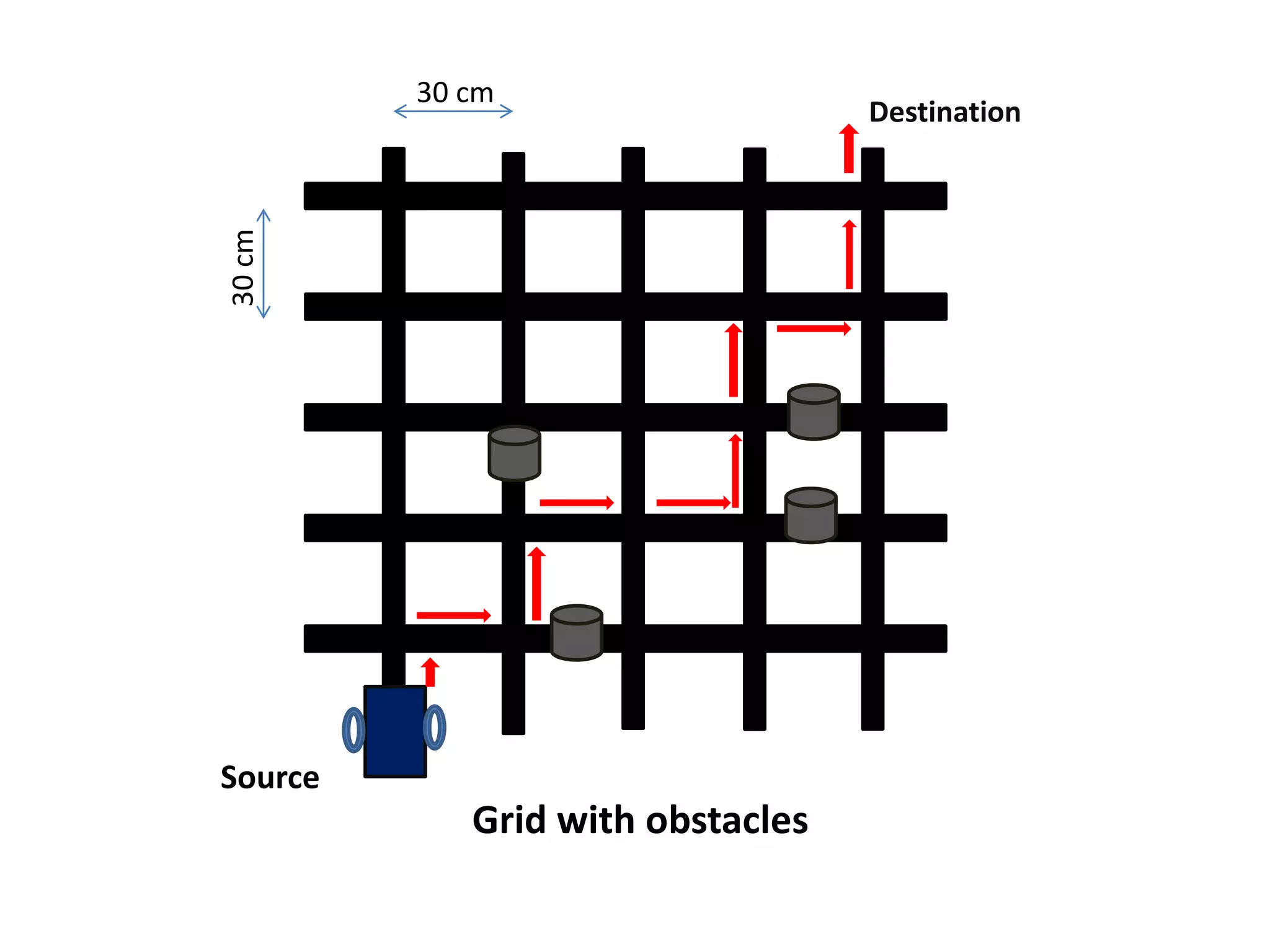
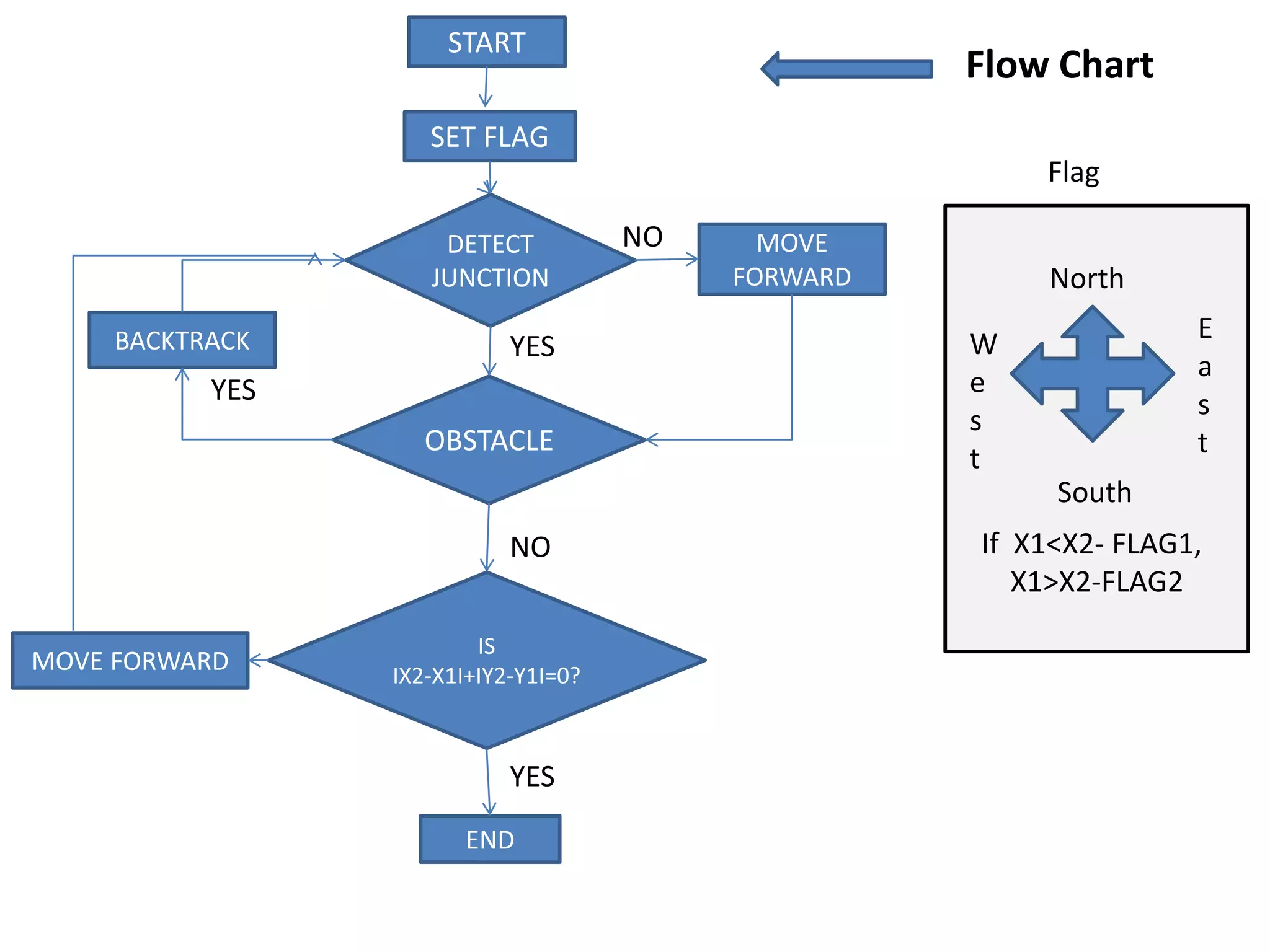
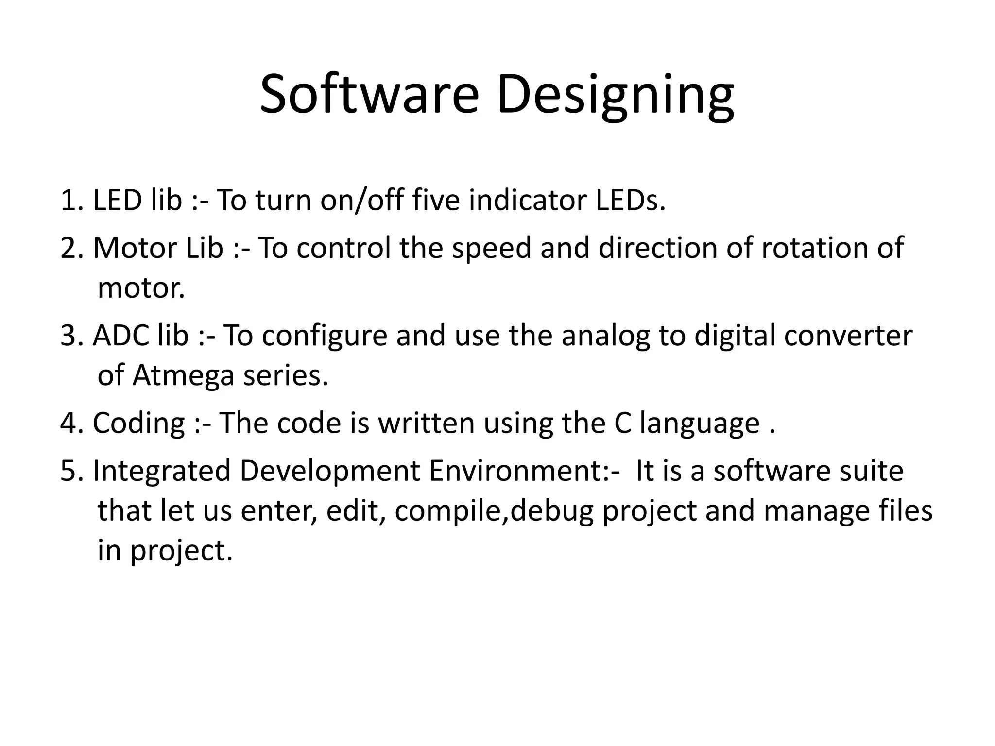
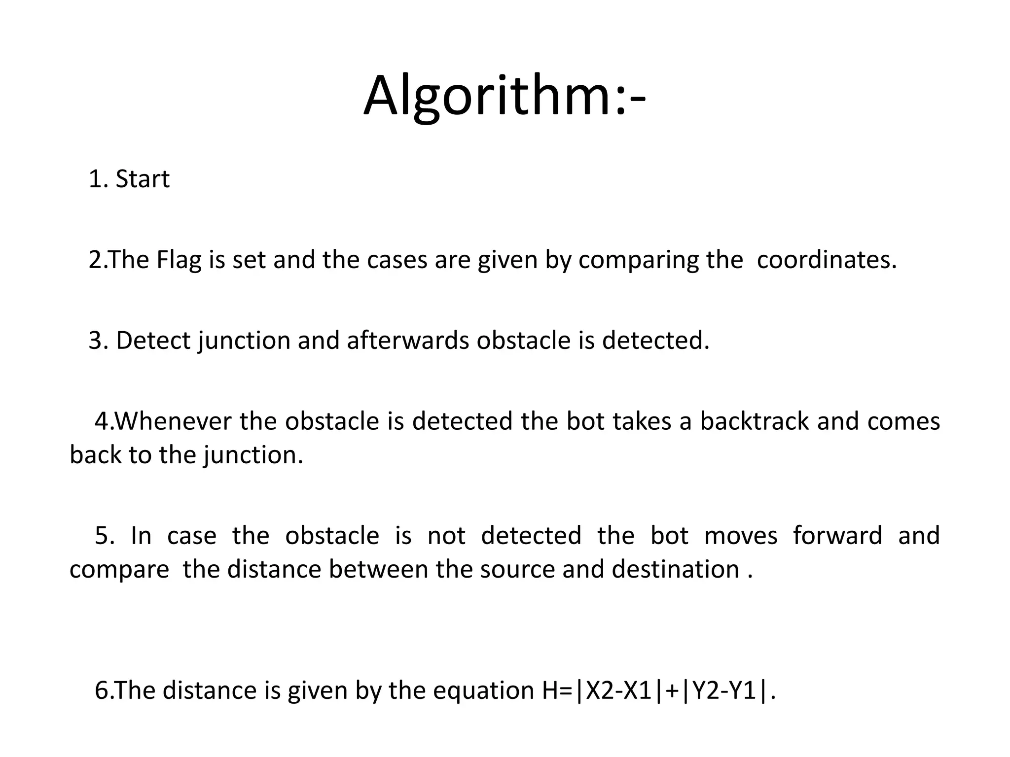
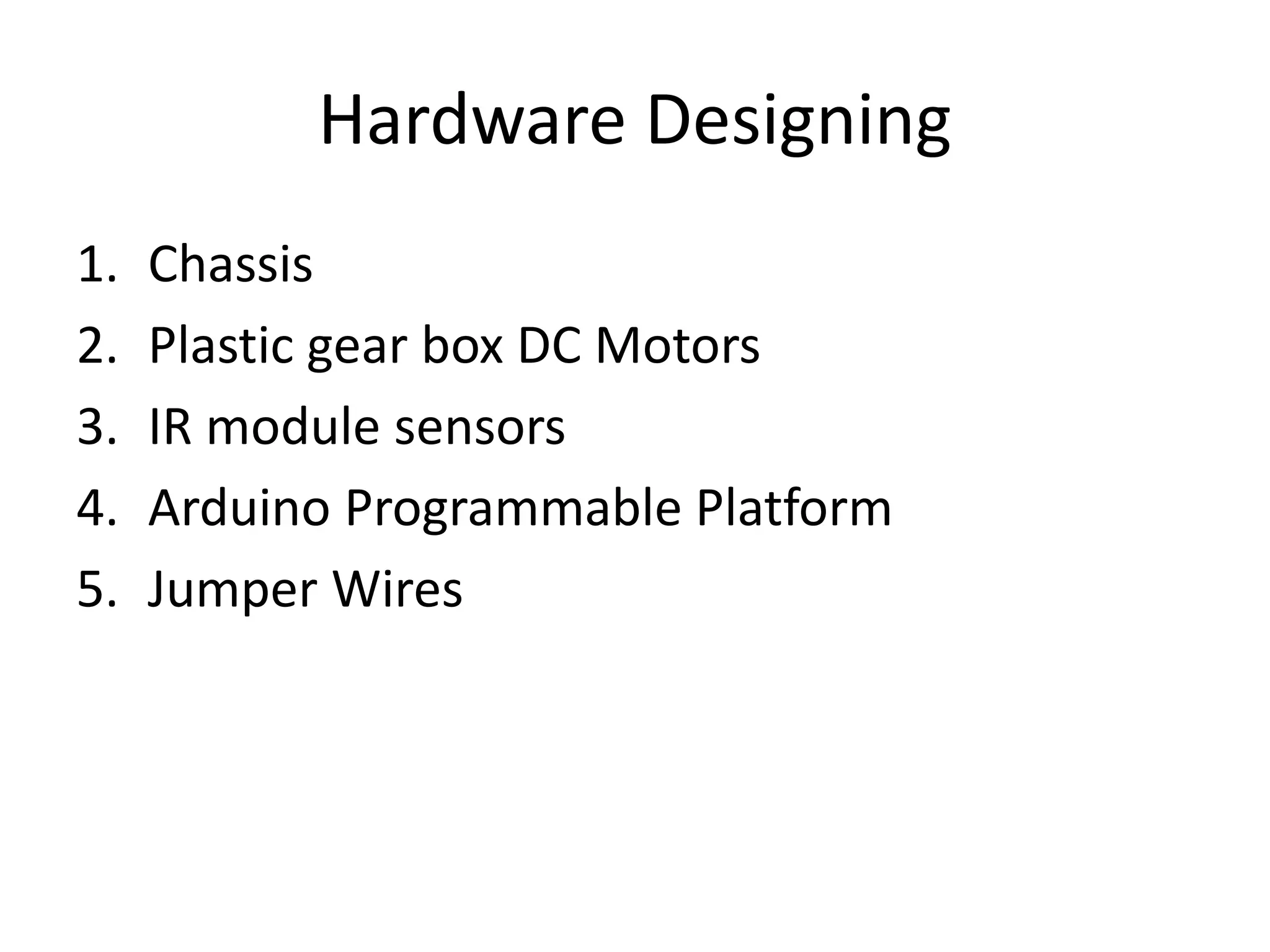
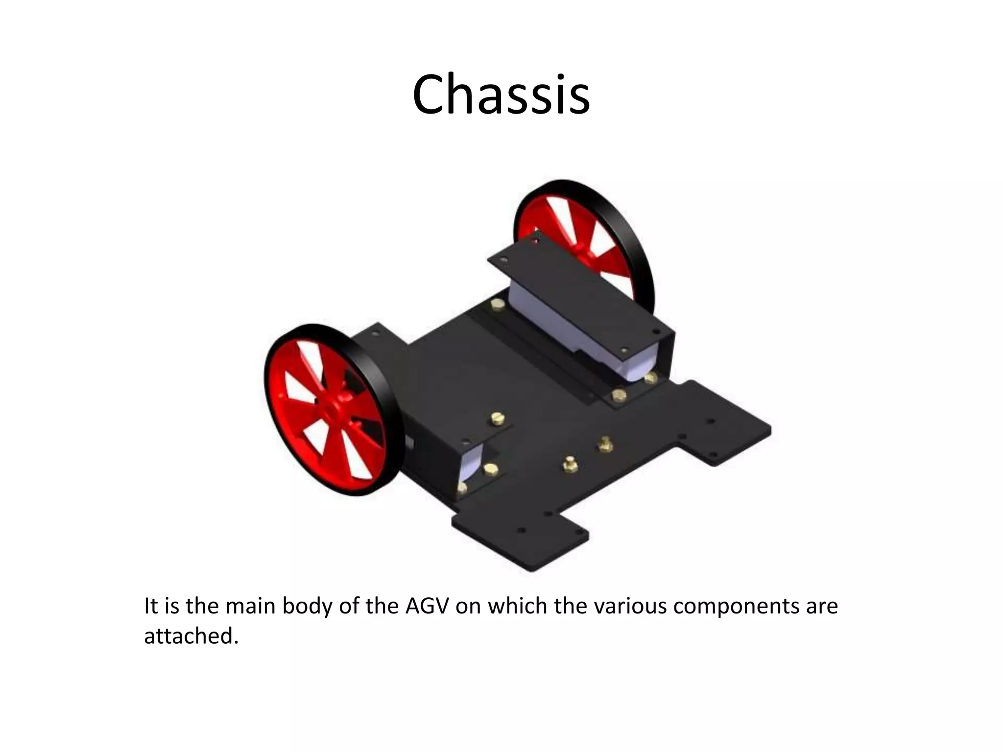
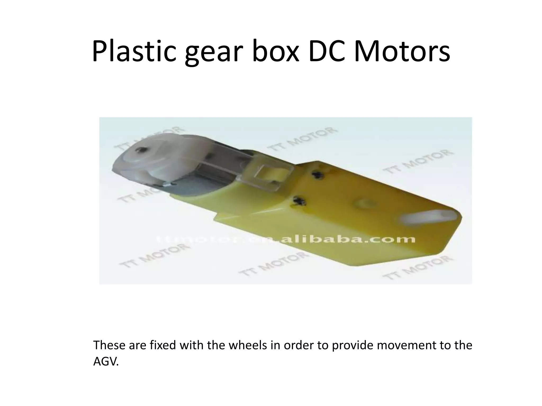
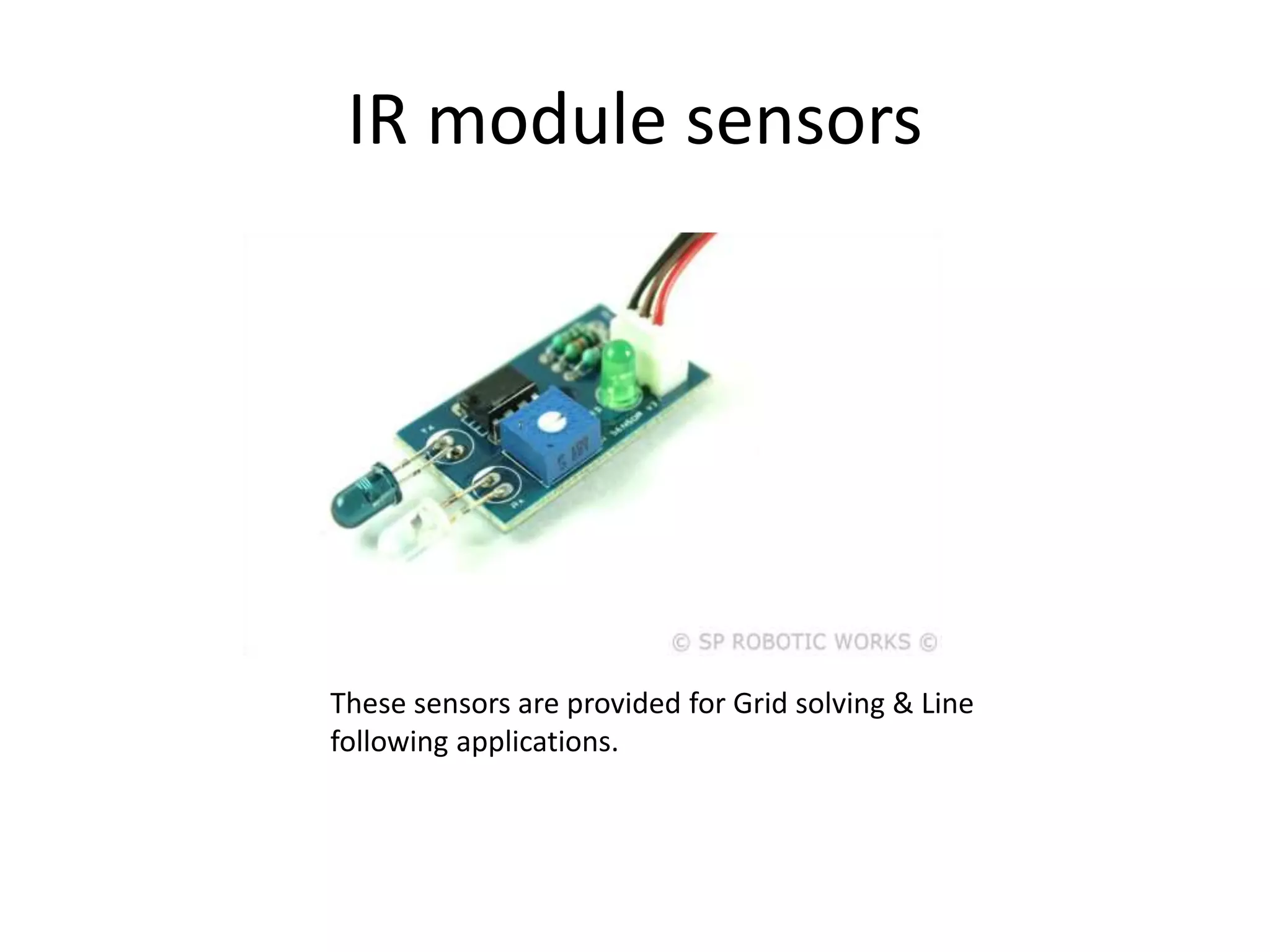
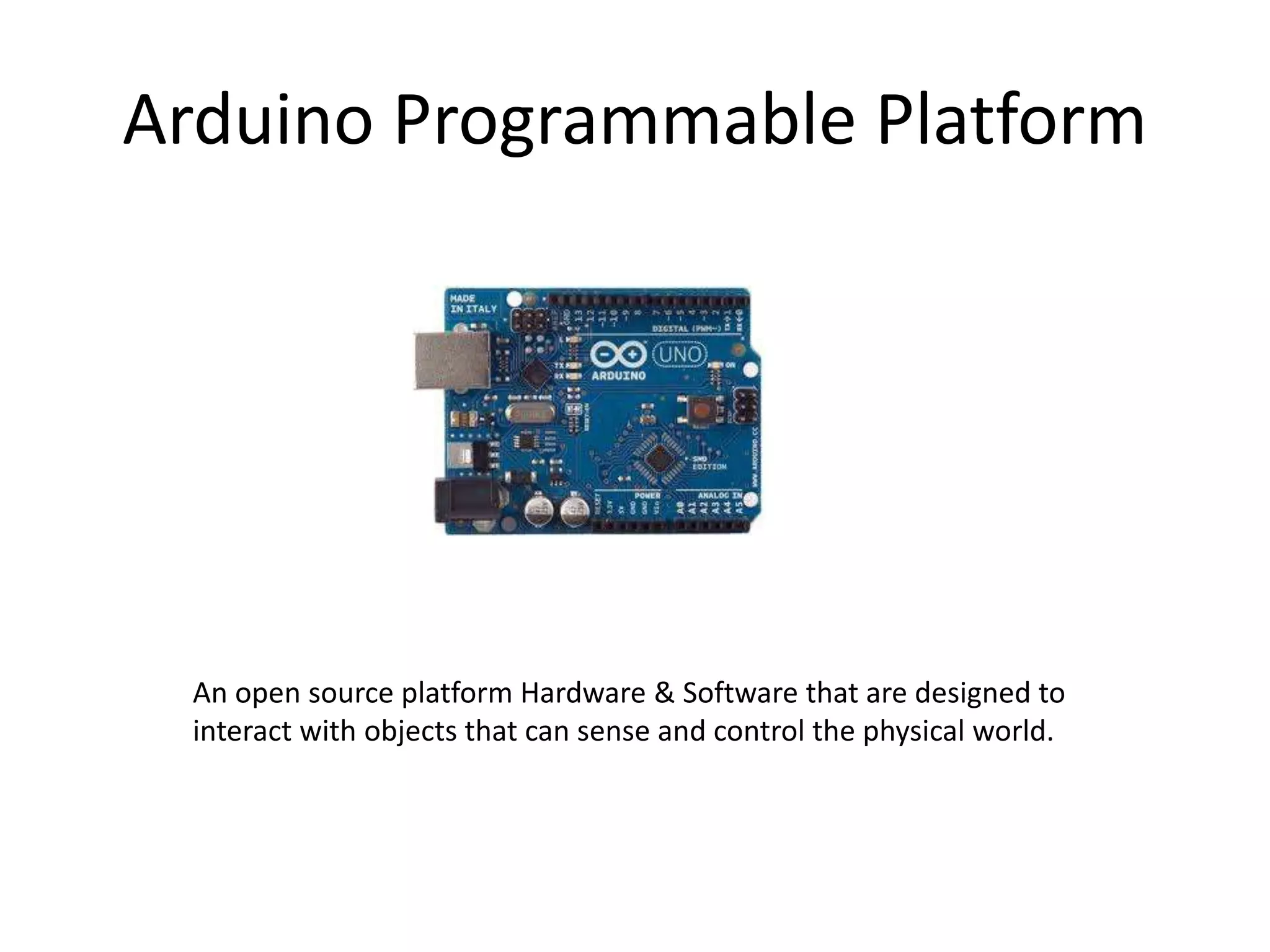
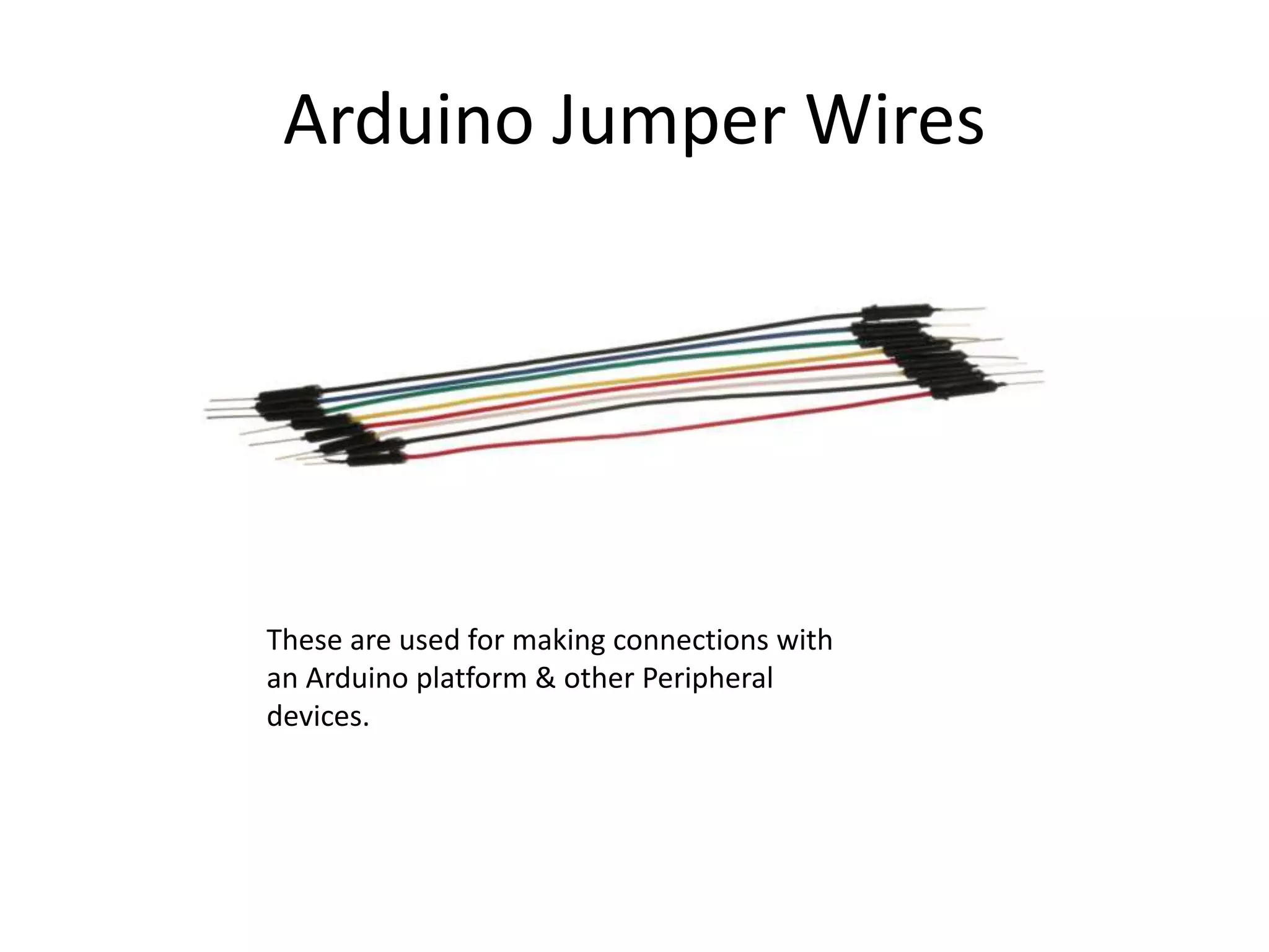
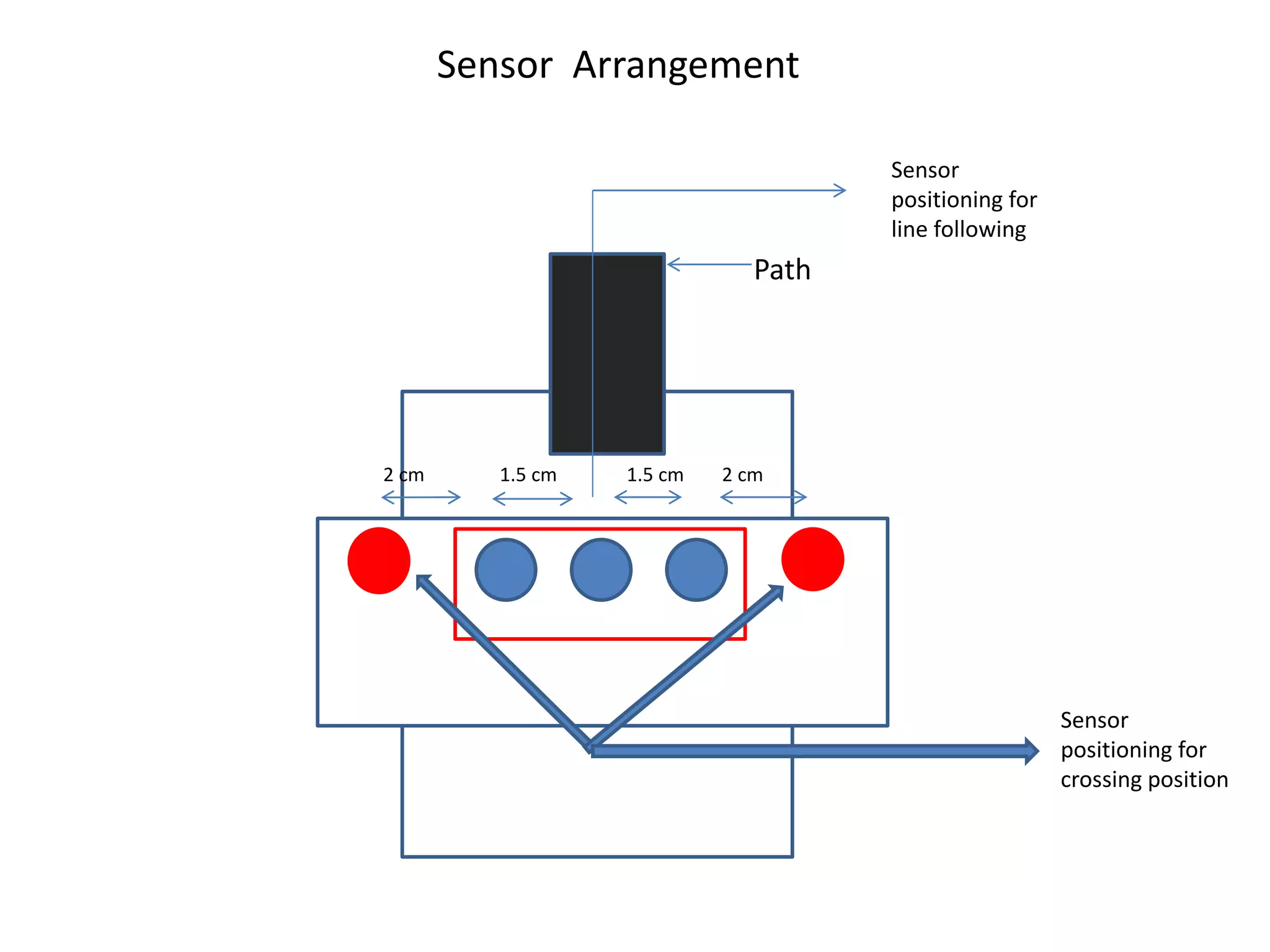
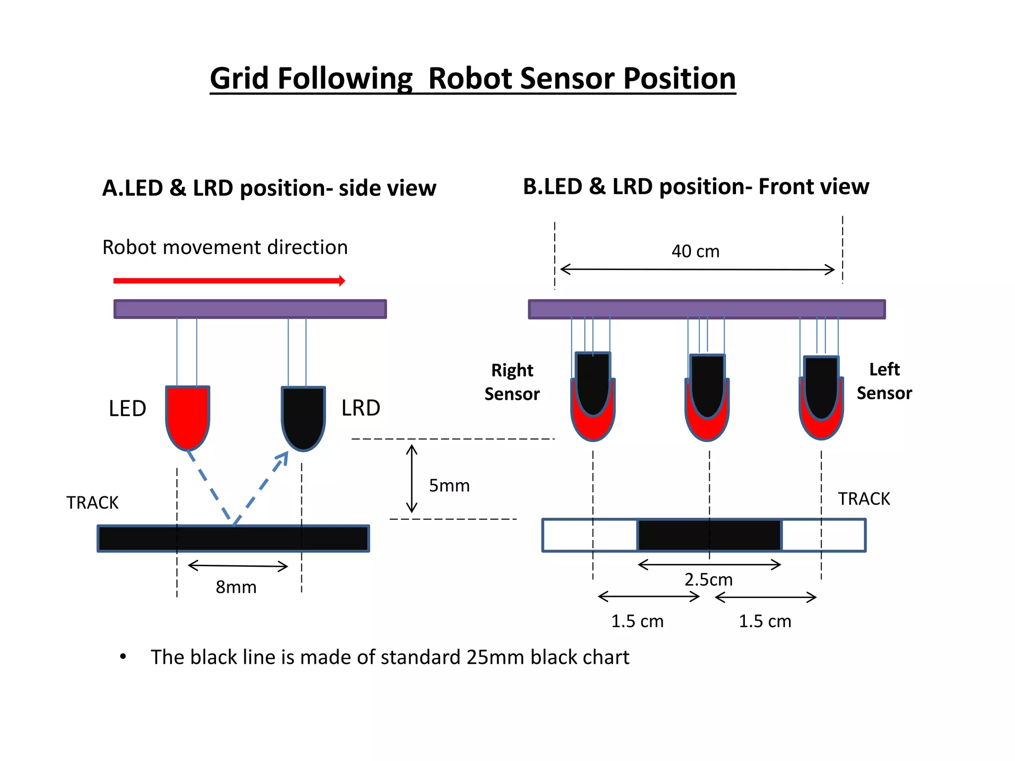
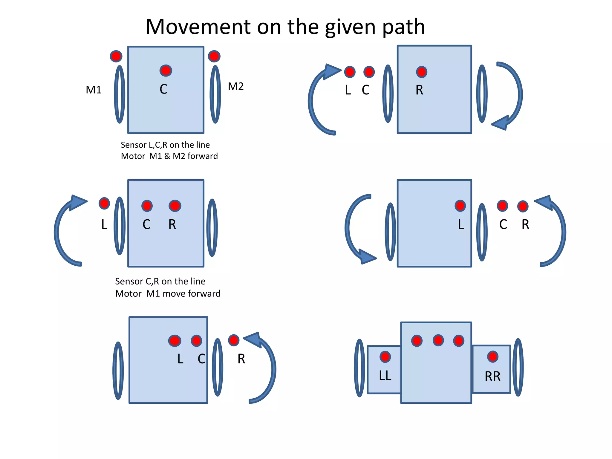
Intelligent Path Navigation & Control
for Automated Guided Vehicles(AGVs)
Project done under the guidance of
Prof. Malay Kumar Pandit
Dean
School of Electronics & Informatics
Submitted by:-
Chiranjit Agarwal
Awanish Kumar
Akash Raj
Amrit Sagar
Kaonteya Kumar Ashish
Objective:
• Intelligent path navigation by AGV(for
given source to destination).
• Grid based approach.
• Obstacle detection and maneuvering
Source
Destination
Grid with obstacles
30 cm
30cm
MOVE
FORWARD
BACKTRACK
START
DETECT
JUNCTION
MOVE FORWARD
END
NO
YES
YES
SET FLAG
Flag
North
W
e
s
t
E
a
s
t
South
If X1<X2- FLAG1,
X1>X2-FLAG2
OBSTACLE
NO
YES
IS
IX2-X1I+IY2-Y1I=0?
Flow Chart
Software Designing
1. LED lib :- To turn on/off five indicator LEDs.
2. Motor Lib :- To control the speed and direction of rotation of
motor.
3. ADC lib :- To configure and use the analog to digital converter
of Atmega series.
4. Coding :- The code is written using the C language .
5. Integrated Development Environment:- It is a software suite
that let us enter, edit, compile,debug project and manage files
in project.
Algorithm:-
1. Start
2.The Flag is set and the cases are given by comparing the coordinates.
3. Detect junction and afterwards obstacle is detected.
4.Whenever the obstacle is detected the bot takes a backtrack and comes
back to the junction.
5. In case the obstacle is not detected the bot moves forward and
compare the distance between the source and destination .
6.The distance is given by the equation H=|X2-X1|+|Y2-Y1|.
7. If the distance H=0 then the Destination is reached.
8. If H !=0 then the bot will move forward and detect the other junction.
9. End .
Hardware Designing
1. Chassis
2. Plastic gear box DC Motors
3. IR module sensors
4. Arduino Programmable Platform
5. Jumper Wires
Chassis
It is the main body of the AGV on which the various components are
attached.
Plastic gear box DC Motors
These are fixed with the wheels in order to provide movement to the
AGV.
IR module sensors
These sensors are provided for Grid solving & Line
following applications.
Arduino Programmable Platform
An open source platform Hardware & Software that are designed to
interact with objects that can sense and control the physical world.
Arduino Jumper Wires
These are used for making connections with
an Arduino platform & other Peripheral
devices.
Sensor Arrangement
Sensor
positioning for
crossing position
Sensor
positioning for
line following
2 cm 1.5 cm 1.5 cm 2 cm
Path
A.LED & LRD position- side view
Robot movement direction
B.LED & LRD position- Front view
LED LRD
Right
Sensor
Left
Sensor
5mm
1.5 cm 1.5 cm
2.5cm
40 cm
TRACKTRACK
8mm
• The black line is made of standard 25mm black chart
Grid Following Robot Sensor Position
C
L C R
L C R
L C R
L C R
LL RR
M1 M2
Sensor L,C,R on the line
Motor M1 & M2 forward
Movement on the given path
Sensor C,R on the line
Motor M1 move forward
Direction Turn Set Direction Set Coordinate
North Forward North Y++
North Right East X++
North Left West X--
East Forward East X++
East Right South Y--
East Left North Y++
West Forward West X--
West Right North Y++
West Left South Y--
South Forward South Y--
South Right West X--
South Left East X++
Calculating Direction
North
South
W
e
s
t
E
a
s
t
Sources of Errors
 It will not work in bright light.
 Damage in the black strip or damage due to the overuse as a
result of which the sensors will not respond properly.
 In the rainy season the problem is caused due to the
absorption of water.
 The distance between the sensors should be maintained
properly.
References:
[1].people.ece.cornell.edu/land/courses/ece4760/Final
Projects/s2007/jxd2/djd36_jxd2/neuralrobot.htm
[2].Genci Capi, Member, IEEE Mitsuki Kitani, Zulkifli Mohamed- Simultaneous
Evolution of Neural Controllers for Multi Robot Formation Control
[3].Dean A. Pomerleau, Carnegie Mellon University, School of Computer
Science, Knowledge-based Training of Artificial Neural Networks for
Autonomous Robot Driving
[4].en.wikipedia.org/human computer interaction
[5].Robot Modeling and Control-Mark w. Spong,Seth Hutchinson, M
Vidyasagar,WILEY STUDENT EDITION.
Presentation1 (2)

Presentation1 (2)

  • 1.
    Intelligent Path Navigation& Control for Automated Guided Vehicles(AGVs)
  • 2.
    Project done underthe guidance of Prof. Malay Kumar Pandit Dean School of Electronics & Informatics Submitted by:- Chiranjit Agarwal Awanish Kumar Akash Raj Amrit Sagar Kaonteya Kumar Ashish
  • 3.
    Objective: • Intelligent pathnavigation by AGV(for given source to destination). • Grid based approach. • Obstacle detection and maneuvering
  • 4.
  • 5.
  • 6.
    Software Designing 1. LEDlib :- To turn on/off five indicator LEDs. 2. Motor Lib :- To control the speed and direction of rotation of motor. 3. ADC lib :- To configure and use the analog to digital converter of Atmega series. 4. Coding :- The code is written using the C language . 5. Integrated Development Environment:- It is a software suite that let us enter, edit, compile,debug project and manage files in project.
  • 7.
    Algorithm:- 1. Start 2.The Flagis set and the cases are given by comparing the coordinates. 3. Detect junction and afterwards obstacle is detected. 4.Whenever the obstacle is detected the bot takes a backtrack and comes back to the junction. 5. In case the obstacle is not detected the bot moves forward and compare the distance between the source and destination . 6.The distance is given by the equation H=|X2-X1|+|Y2-Y1|.
  • 8.
    7. If thedistance H=0 then the Destination is reached. 8. If H !=0 then the bot will move forward and detect the other junction. 9. End .
  • 9.
    Hardware Designing 1. Chassis 2.Plastic gear box DC Motors 3. IR module sensors 4. Arduino Programmable Platform 5. Jumper Wires
  • 10.
    Chassis It is themain body of the AGV on which the various components are attached.
  • 11.
    Plastic gear boxDC Motors These are fixed with the wheels in order to provide movement to the AGV.
  • 12.
    IR module sensors Thesesensors are provided for Grid solving & Line following applications.
  • 13.
    Arduino Programmable Platform Anopen source platform Hardware & Software that are designed to interact with objects that can sense and control the physical world.
  • 14.
    Arduino Jumper Wires Theseare used for making connections with an Arduino platform & other Peripheral devices.
  • 15.
    Sensor Arrangement Sensor positioning for crossingposition Sensor positioning for line following 2 cm 1.5 cm 1.5 cm 2 cm Path
  • 16.
    A.LED & LRDposition- side view Robot movement direction B.LED & LRD position- Front view LED LRD Right Sensor Left Sensor 5mm 1.5 cm 1.5 cm 2.5cm 40 cm TRACKTRACK 8mm • The black line is made of standard 25mm black chart Grid Following Robot Sensor Position
  • 17.
    C L C R LC R L C R L C R LL RR M1 M2 Sensor L,C,R on the line Motor M1 & M2 forward Movement on the given path Sensor C,R on the line Motor M1 move forward
  • 18.
    Direction Turn SetDirection Set Coordinate North Forward North Y++ North Right East X++ North Left West X-- East Forward East X++ East Right South Y-- East Left North Y++ West Forward West X-- West Right North Y++ West Left South Y-- South Forward South Y-- South Right West X-- South Left East X++ Calculating Direction North South W e s t E a s t
  • 19.
    Sources of Errors It will not work in bright light.  Damage in the black strip or damage due to the overuse as a result of which the sensors will not respond properly.  In the rainy season the problem is caused due to the absorption of water.  The distance between the sensors should be maintained properly.
  • 20.
    References: [1].people.ece.cornell.edu/land/courses/ece4760/Final Projects/s2007/jxd2/djd36_jxd2/neuralrobot.htm [2].Genci Capi, Member,IEEE Mitsuki Kitani, Zulkifli Mohamed- Simultaneous Evolution of Neural Controllers for Multi Robot Formation Control [3].Dean A. Pomerleau, Carnegie Mellon University, School of Computer Science, Knowledge-based Training of Artificial Neural Networks for Autonomous Robot Driving [4].en.wikipedia.org/human computer interaction [5].Robot Modeling and Control-Mark w. Spong,Seth Hutchinson, M Vidyasagar,WILEY STUDENT EDITION.