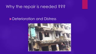
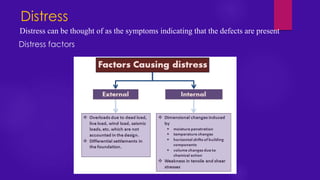
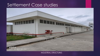
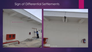
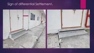
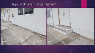
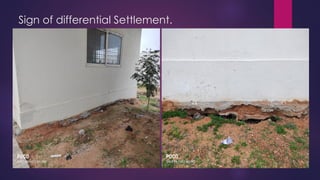
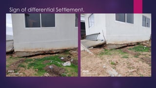
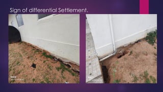
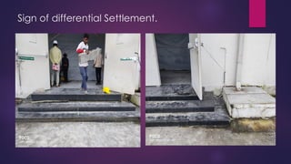
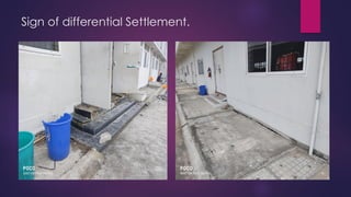
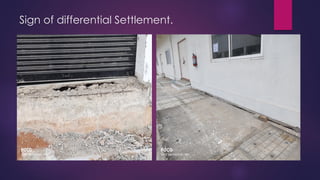
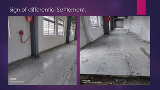
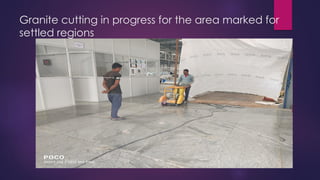
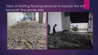
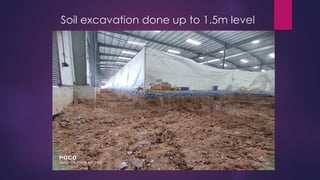
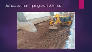
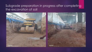
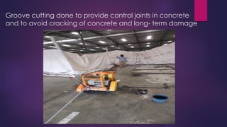
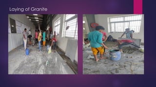
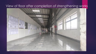
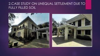
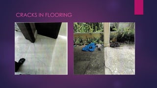
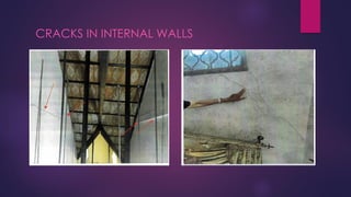
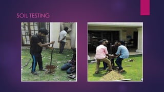
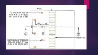
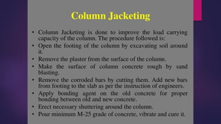
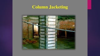
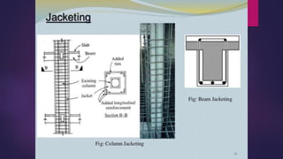
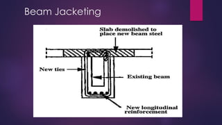
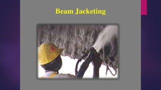
3. REPAIR, RESTORATIONAND RETROFITTING
Repair: To bring back the position of the structure either whole or part
to its previous condition so that it gives performance same as
previous.(Most of the time it is not related to strength aspect)
Some examples of repair…….
➢ Checking the wiring of building
➢ Replastering of any wall if required
➢ Repairing of damaged flooring
➢ Repair of door and window
➢ Checking or repairing of pipe line connections, gas line connections and plumbing
serveries.
➢ Relaying disturbed roof tiles
4. REPAIR, RESTORATION,REHABILITATIONAND RETROFITTING
➢ Restoration: The process of re-establishing the previous condition of the building by
the materials and methods (Regain the forms and functionality of a structure)
Some of the examples of Restoration…..
➢ To water proof the roof
➢ Removal of damaged portion of masonry and reconstructing it
using rich mortar mix.
➢ Treatment for water seepage and structural damage
➢ Restoration of heritage or monumental building structures
5. REPAIR, RESTORATIONAND RETROFITTING
Rehabilitation: Rehabilitation of a building means altering or upgrading a building
or a structure to present need by means of modification or alteration.
Some of the examples of Rehabilitation…..
➢ To modify the structure for more usage/utility (Eg. Increase capacity of the party hall)
➢ Modifying the building under comfortability aspect.
➢ Modifying the building for appearance/strength aspect
6. REPAIR, RESTORATIONAND RETROFITTING
Retrofitting:
The process of strengthening of structure along with the structural system,
In compliance with all relevant codal provisions during its service period.
or
It is the modification of existing structures to make them more resistant to seismic
activity, ground motion, or soil failure due to earthquakes.
Earthquake creates great devastation/damage in terms of life, money and
failures of structures.
Earthquake Mitigation is an important field of study from long time.
Seismic Retrofitting is a collection mitigation techniques for Earthquake
Engineering.
It is of utmost importance for historic monuments, areas prone to
severe earthquakes and tall or expensive structures
The retrofit techniques are also applicable for other natural hazards such as tropical
cyclones, tornadoes, and severe winds from thunderstorms.
7. REPAIR, RESTORATIONAND RETROFITTING
When is Seismic Retrofitting Needed ?
The two circumstances are:-
Earthquake damaged buildings, and Earthquake-vulnerable
buildings(with no exposure to severe earthquakes)
Some examples of retrofitting ………(Refer IS13920,1893)
➢ Increasing the lateral strength in one or both directions, by
reinforcement or by increasing wall areas or the numbers of walls
and columns
➢ Giving unity to the structure by providing a proper connection
between resisting elements.
➢ Eliminating features that are sources of weakness, asymmetrical
plan distribution of resisting members, abrupt changes of stiffness
from one floor to the other.
➢ Avoiding the possibility of brittle modes of failure by proper
reinforcement and connection of resisting members.(IS13935)
10. Problems to be Addressed
Aging of structures-Expected life and performance
Deterioration of concrete-causes and effects
Durability considerations
Distress diagnostics and performance monitoring-Non-Destructive test
methods.
Damage assessment and evaluation models
Structural condition assessment
Analysis and Design of repairs-suitable repair techniques
Materials for protection, repair and rehabilitation
Repair Techniques
Strengthening techniques
Seismic retrofitting
11. Distress
Distress can be thought of as the symptoms indicating that the defects are present
Distress factors
12. Types of Distress
1.Blow holes
Surface voids are small pop-outs or holes that appear on the outer
surface of the concrete due to entrapped air. A significant challenge
of the concrete industry today is to control the concrete surface
quality fulfilling all the design mix criteria. Sometimes these voids
may be unappealing to the public eye, but it is essential to repair
for bridge/structural construction work.
13. Sometimes in portions of the vertical, bottom and inclined surfaces of
precast/cast-in-situ members, the appearance of small Blowholes/Surface
voids/Bugholes due to air bubbles are observed.
Though specification prescribes filling these with cement mortar – but in some
cases because of the importance of the structure and its future durability it
should be sealed and finished with Polymer mortar using Polymer Latex of a
reputed manufacturer in prescribed dosage for gauging the mortar.
Repair Technique
14. 3.Disintegration - Two terms generally used to mark this they are
Scaling – Concrete scaling is the local flaking or peeling off of the near-surface
concrete due to environmental factors like freezing and thawing. Other factors that
may contribute to the initiation of concrete scaling are the use of low-strength
concrete, deicing salts, and a high water-cement ratio in a concrete mixture.
Types of Distress
15. Repairing Concrete Scaling
Remove loose concrete and clean the surface having any dirt and
debris.
Dampen the cleaned concrete area and apply a thin layer of
cement paste before concrete placement for resurfacing.
Place proper concrete type to resurface the damaged area. Latex-
modified concrete (polymer-modified cement concrete) is a good
option.
Apply pressure on the concrete while the finishing operation is being
performed.
The construction joints can be sealed with an epoxy resin sealer.
16. Dusting-White powdery formation on the
surface of hardened concrete that receives
excessive traffic. Formation of loose powder
resulting from disintegration of surface of
hardened concrete is called dusting or
chalking.
1.Sandblast, shot blast or use a high-pressure washer to remove the weak
surface layer.
2.To minimize or eliminate dusting, apply a commercially available chemical
floor hardener, such as sodium silicate (water glass) or metallic zinc or
magnesium fluosilicate, in compliance with manufacturer’s directions on
thoroughly dried concrete. If dusting persists, use a coating, such as latex
formulations, epoxy sealers, or cement paint.
Repair technique
Dusting
17. 3. Cold joints-
A cold joint happens when fresh concrete is poured on top of existing
concrete. It looks like a huge crack and some home buyers even
mistaken them with structural cracks. The truth is that cold joints rarely
create structural integrity issues. Concrete Cold joint is defined as the
plane of weakness in concrete due to an interruption or delay in the
concreting operations.
18. Repair Technique
The use of bonding agents to enhance adhesion between old and
new concrete.
Saw-cutting and concrete re-pour to increase integration between
fresh and set batches.
The use of mechanical connectors, such as dowel bars, to increase
structural continuity.
The use of epoxy injection
19. 4. Honey Combing- It refers to voids caused by the mortar not filling the
spaces between the coarse aggregate particles.
•The honeycombs are caused by improper workability of concrete, using stiff
concrete which is hard to place.
•Additional water cement ratio than the allowable limit on-site for better
workability. The excess amount of water cement ratio will result in separation of
aggregates from the mortar.
•Excess Vibration cause separation of aggregate
20. Remove all the loose aggregate and concrete from the affected honeycombed area.
Do this gently with the help of a wire brush.
Next, clean the concrete surface of dirt and fine particles with a brush. Wash the
surface with water and allow it to dry for about 2 to 3 hours.
Install a formwork if required or apply a high-strength grout.
Prepare a grout mixture with water and binder (GP-2 or MP Birla Cement Ultimate Build
right etc). Be mindful of the water quantity used so that it doesn’t get too slurry or stiff.
Fill the affected honeycombed area with the grout mixture.
Remove the formwork if it was applied and cure the surface. Allow it to dry for about 24
hours.
Repair Technique
21. 5.Crazing- It is the network of fine random cracks that are formed due to
the shrinkage of the layer relative to the base concrete. It does not pose
any structural or Serviceability problem.
Excessive Use of Cement – To give a smooth finish on the concrete finish,
labours try to sprinkle cement on the surface. Later the cement will dry
and make way to crazing.
Excessive Vibration – Excessive vibration on the concrete makes the blue
metal to settle down and let the cement slurry to the top which develop
the crazing
Use of High Workability Concrete – Using high workability concrete for
easy placement often contains excess water which makes the cement
to settle at top.
22. •Prepare a V-shaped groove along the crack using hand tools or a pneumatic tool
•Clean the groove using either air or water-blasting
•Allow the surface of the groove to dry
•Apply poly urethane sealant generously to the groove and allow it to cure.
23. 6.Cracking- Cracking is the line of separation in the plane of failure.
Type of structure and nature of cracking is the major concern. Cracks in
the concrete does not always mean that the structure is unusable.
• A. Structural Cracks - Structural cracks are those that may occur due
to deficient designs , overloading , abnormal vibrations , use of inferior
quality materials ,foundation placed on uncompacted /loose soils ,
adoption of improper construction practices, poor workmanship, etc.
• B. Non -Structural Cracks - These cracks occur due to the internally
induced stresses in building material or due to the temperature
induced movement of the materials. These cracks appearance of the
structure may give a feeling of instability.
24. MATERIALS FOR CRACK REPAIR
The various materials used for repairs of cracks
are:
➢ Cement Slurry
➢ Cement Mortar
➢ Epoxy resin
➢ Polymer Modified Cementitious Products
➢ Ppolyurethane/Polysulphide
29. 3. STITCHING
Stitching may be used when tensile strength must be re-
pestablished across major cracks.
Stitching involves
drilling holes on both sides of the crack
grouting in U-shaped metal units with short legs called
staples or stitching dogs
30.
31. Prestressing steel
Post-tensioning is often the desirable solution when a major portion of a
member must be strengthened or when the cracks that have formed must
be closed. This technique uses pre stressing strands or bars to apply a
compressive force. Adequate anchorage must be provided for the
prestressing steel and care is needed so that the problem will not merely
migrate to another part of the structure.
32. Additional Reinforcement for Crack Repair Conventional
reinforcement
Cracked reinforced concrete bridge girders have been successfully repaired
by inserting reinforcing bars and bonding them in place with epoxy. This
technique consists of sealing the crack, drilling holes that intersect the crack
plane at approximately 90 deg ,filling the hole and crack with injected epoxy
and placing a reinforcing bar into the drilled hole.
33. Types of Distress
7.Settlement Cracks
One of the most common causes of building cracks is a settlement.
This occurs when the soil beneath the foundation compresses or
shifts, causing the foundation to sink or settle. This can cause cracks
in the walls, ceilings, and building floors.
Refer Case study
34. Types of Distress
8. Spalling
Spalling is a term used to describe areas of concrete which have cracked and
delaminated from the substrate. There are a number of reasons why spalling occurs
including freeze thaw cycling, the expansive effects of Alkali Silica Reaction or
exposure to fire. However, the most common cause of spalling is the corrosion of
embedded steel reinforcement bars or steel sections. Corroding steel can expand
up to ten times its original volume, exerting stress on the surrounding concrete.
35. 9.Erosion- It could be due to abrasion, erosion which is marked by
smooth, well-worn abraded surface of concrete, while in cavitation-
erosion concrete appears to be very rough and pitted.
36. 10.Deflection-It is the bending or sagging of the reinforced concrete
structural elements like beams, slabs, columns, etc., which can be due to
overloading, corrosion, or by creep in concrete.
38. 11Corrosion- Rusting of steel in concrete, this results in cracking or spalling.
Anode: Site where metal atoms lose electrons i.e., where corrosion is initiated.
Cathode: Site where electrons flow to and combine with other metallic and non-metallic ion.
Electrolyte: A medium capable of conducting electric current by ionic current flow.
Metallic path: Connection between the anode and cathode that completes the circuit.
Mechanism of Corrosion: The corrosion process that takes place in concrete is
electrochemical in nature very similar to a battery. The mechanism of corrosion involves
four basic elements
39. Effects of corrosion
• Cracking & Spalling: In compressive members, cracking and spalling
of concrete reduces the effective cross section of the concrete, thereby
reducing the ultimate compressive load capacity.
• Reduction of structural capacity: The research conducted on flexural
beams found that in steel with more than 1.5 percent corrosion, the
ultimate load capacity began to fall, and
at 4.5 percent corrosion, the ultimate load was reduced by 12 percent
probably as a result of reduced bar diameter.
91. STRENGTHENING OF RCC SLAB
The flexural performance of the slab can be improved by
overlays or underlays. The addition of overlays/underlays will also
increase the stiffness of the slabs and control the excessive deflection.
In the case of negative moment deficiency slab is strengthened by
overlay while in case of positive moment deficiency slab is
strengthened by underlays.
92.
93.
94. SLAB JACKING TECHNIQUE
The technique of pressure injection of grouts for the purpose of lifting or raising or
stabilizing faulty concrete pavement floors and other slab on grade surfaces, is called
slab jacking. It is referred to as slab jacking when lifting of slab is involved or simply
pressure grouting where void filling is the main objective.
APPLICATION:
➢ Highway Maintenance
➢ Repair of expansion joints
➢ Repair of settlement damage in concrete slabs
95.
96. PLATE BONDING
Plat bonding is an inexpensive, versatile and advance
technique for rehabilitation. MS plates are connected mechanically by
bolting/welding.
Plate Bond can increase
Strength
Stiffness
Ductility
Stability, of the RCC element
97.
98.
99. FIBRE WRAP TECHNIQUE
The carbon fiber(CF), carbon fiber reinforced polymer
(CFRP)wrap technique, also know as composite fiber
system is a structural strengthening technique increases
load carrying capacity (shear, flexural, compressive)
and ductility of RCC member without causing any
distress or destruction To the existing concrete.
100.
101.
102. Reference
Aitken, C. G. G., and F. Taroni. 2004. Statistics and the evaluation of
evidence for forensic scientists. Hoboken, NJ: Wiley.
Aldy, J. E., and W. K. Viscusi. 2003. Age variations in workers’ value of statistical life.
Cambridge
Faber, M. H. 2005. “On the treatment of uncertainties and probabilities in
engineering decision analysis.” J. Offshore Mech. Arct. Eng. 127 (3):
243–248. https://doi.org/10.1115/1.1951776.
Gambino, S. J., and R. B. Gilbert. 1999. “Modeling spatial variability in pile capacity for
reliability-based design.” In Analysis, design, construction,and testing of deep foundations,
edited by J. M. Roesset, 135–149.New York: ASCE.
Garbulewski, K., S. Jabłonowski, and S. Rabarijoely. 2009. “Advantage ofBayesian approach
to geotechnical designing.” Ann. Warsaw Univ. Life