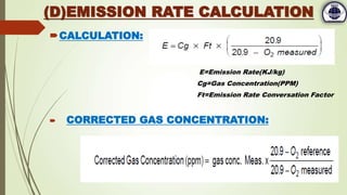
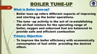
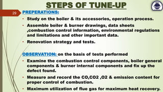
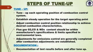
DEPARTMENT OF MECHANICAL ENGINEERING, 4TH YEAR
-: PRESENTATION ON :-
CASE STUDY OF A CONDEMNED BOILER &
METHODS TO RE-ESTABLISH IT.
SUBMITTED BY:
Aditya Bhattacharjee- Roll No: 27600712006
Argha Das - Roll No: 27600712016
Indranil Chakraborty - Roll No: 27600712038
Sudipta Raha - Roll No: 27600711053
DATE: 11/06/2016
UNDER GUIDENCE OF:
Prof. Mr. DEBAJIT BANERJEE
CONTENTS
 Acknowledgement
 Introduction
 Abstract of HSDCL
 Definition of Boiler
 Specification of Boiler
 Flow Diagram of the process
 Boiler Accessories
 Scope of work for Boiler maintenance & repairing
I. Dismantling of Boiler & its accessories
II. Pressure test of Ducts & stream pipeline
 Scope of work after renovation
I. Flue Gas Analysis
II. Boiler Tuning
 Conclusion
 Bibliography
2
ACKNOWLEDGEMENT
We are using the opportunity to express Ours's gratitude to everyone who
supported us throughout this project. We are thankful for their aspiring guidance,
invaluable constructive criticism and friendly advice during project work. We are
sincerely grateful to them for sharing their truthful and illuminating views on a
number of issues related to this project.
I expressed my warm thanks to Director Mr. ALOK SARAF ; Project Co-ordinator
Mr. VEDANT SARAF ; GM Mr. S.C.CHANDRA & engineers Mr. Natwar Gupta ; Mr.
Debabrata Das ; Mr. Anway Chakraborty for their support and guidance at
Hindustan Storage & Distribution Co. Ltd.
I would also like to thank my project guide Mr. Debajit Baneerjee
from the Budge Budge Institute of Technology and all the people who provided
me with the facilities and conductive conditions for this project.
Thanking You,
Aditya Bhattacharjee
Argha Das
Indranil Chakraborty
Sudipta Raha
3
INTRODUCTION
Boiler is one of the most important devices in a
power plant or in industries where a source of
stream is required as a source of heat.
It is the a device used to create stream by applying
heat energy to water and the heat is supplied from
the combustion of fuel. Hence brake down of boiler
at any time may leads to severe damage to the
industrial processes. Hence our project reflects the
detail procedures to re-establish and start-up a
condemned boiler such that it fulfil the industrial
need by maximizing the economy while maintaining
fuel economy.
4
ABSTRACT ON HSDCL
Hindustan Storage & Distribution Company Ltd is a Public
incorporated on 07 December 1982. It is classified as Non-govt.
company and is registered at Registrar of Companies, Kolkata.
Directors of Hindustan Storage & Distribution Company Ltd are Alok
Saraf, Sawarmal Agarwal.
This company is basically a oil storage & distribution company which
import and exports a various kind of edible oils, lub oils and chemicals.
The products are stored in several tank with capacity range 500 kl to
8000 kl. The company have pipelines of 2.5 Km almost from Jetty to
their storage tank.
Product type:
CPO- Crude Palm Oil
RBDPO- Refined Bleached Deodorized Palm Oli
LAB- Linear Alkyl Benzine
LUBE- Lubricant Oil Ketrul D-80
SUPER SPIRIT
5
REQUIREMENT OF BOILER AT HSDCL
Defination Of Boiler:
 A boiler is an enclosed container that provides a mean fro heat of
combustion to be transferred to the working medium(water) until it
become heated or convert in steam.
 The heated steam can be utilized for transferring the heat in several
processes that consume the heat of the stream and turns in work or
just to heat another substance.
Requirement of Boiler:
 The products like CPO & RBDPO which are stored in the company have
slip melting point at about 35 degree centre grade .That means during
winter seasons as the atm. temperature falls below 35 degrees they
starts solidifying and about 15-16 degrees of atmospheric temperature
the oils get solidified. Hence hot steam under pressure is used to melt
the oils. To generate the hot stream a package boiler REVOMAX PLUS
is installed in the site.
6
SPECIFICATION OF BOILER
REVOMAX PLUS (STEAM GENERATOR)
Model: R*D-850/164
Type: Package stream generator
Manufacturing Year: 2003
Fuel: Furnace Oil
Rating: 415V ; 3 Phase ; 50 HZ
Capacity: 850 kg/hr
Design pressure: 10.54 -17.50 kg/cm^2
Fuel Firing System: Pressure Jet-Reverse
Flue,Dual Block
Make: Thermax Ltd.
7
(A) Study of the Boiler Accessories
 Combustion Chamber: It internal space of
the boiler where combustion take place.
 Steam coil: The coil through which the
water circulates and heats up to form
stream .It is made up of mild steel .
 Economizer: Heat exchanger(shell tube
type) to preheat the feed water before it
enters the combustion chamber by
recovering the heat of flue gas.
 Heat Optimizer: Preheat the water
entering the economizer and optimize the
temperature of water leaving the
economizer and entering the feed water
pump.
 Feed water pump: 3 cylinder ,positive
displacement, reciprocating pump to feed
the water to the steam coil at desired
pressure and rate.
8
Combustion
Chamber
Economizer
COIL
Feed Water Pump
 Burner Gun: It is a heating device
which burns the fuel oil. The fuel is
atomized through the nozzle under
pressure and it is ignited by
electric sparks generated by 2
sets of electrodes.
 Oil Filter: They minimize the dirt
and water that can enter into the
boiler fuel system. This not only
maximizes the efficiency of your
furnace but its longevity as well.
 Water Softeners: Removes the
minerals calcium, magnesium and
metal cations from hard water.
This is very essential to eliminate
the formation of scales on the
equipments.
9
OIL FILTER BURNER GUN
(A) Study of the Boiler Accessories
WATER
TANK
WATER SOFTNER
ANION CATION
HEAT
OPTIMIZER
BOILE
R
ECONOMIZER
FEED
WATER
PUMP
CHIMNEY
FUEL
TANK
FILTE
R
FUEL
PUMP
OIL
PREHEATE
R
STEAMLINE TO TANKS
FILTE
R
WATER
FUEL
FLUE
FLOW CHART OF THE PROCESS
10
(B)Scope of work for Boiler maintenance &
repairing
(1)Dismantling of Boiler & its accessories:
Boiler parts and accessories were dismantled
using overhead chain-pulley & gas cutter.
(2)Pressure test of Ducts and Steam Line:
Commenced by using compressor, manifolds,
pressure gauges, temperature recorder.
11
Results of Dismantling of Boiler & its Accessories
Results after Dismantling of Boiler & its accessories
EQUIPMENT OBSERVATION TEST STATUS
OUTER JACKET Damaged due to rusting Replaced
INTERMEDIATE JACKET
Ceramic insulations are
damaged
To be renewed
STEAM COIL Rusting & Scales Pressure Tested Found OK
ECONOMISER
Outer Cover & Inside Cover
damaged due to rusting
Complete set-up was replaced
CONTROL PANEL All circuits are intact Checked by Electricians Found OK
PUMPS(Reciprocating Water
Pump & Fuel Pump )
Unused since long days
Operated on No Load
condition
Shaft was moving at required
speed(rpm). Hence it is found
OK.
SENSORS Damaged due to no longer use Checked by Electricians Replaced with the new one.
INSULATIONS
Glass wool insulations are
totally damaged
Replaced
BURNER ASSEMBLY In good shape Found Ok
PRESSURE GAUGES Working Found OK
WATER SOFTNERS
Anion and cation exchanger
are damaged
Tested by specialized
technicians
Replaced
12
Images of damaged parts of Boiler
13
14
Images of damaged parts of Boiler
(B)Scope of work for Boiler maintenance &
repairing
 (2)Pressure Test of Ducts & Streamline:
Pressure test of Ducts & streamline are conducted.
Process:
 Compressed hot air at around 50 degree centigrade was allowed to pass
through the stream line while all the valves were closed.
Pressure gauges and temperature recorder were installed at the inlet and
outlet of the pipelines.
The operation was commenced at 1.5 times higher than the design
pressure of the system.
 RESULT:
Pressure drop, temperature drop & several leakages were found.
Therefore hence total insulation has to be replaced & the pipeline has to
be repaired by arc welding.
15
(C)Scope of work after Renovation:
Flue Gas Analysis
Boiler Tuning
16
Flue Gas Analysis
PURPOSE:
 Increase fuel economy.
 Decrease undesirable emissions.
 Improve safety of burning equipments.
OBJECTIVE:
 Combustion analysis involves the measurement of gas concentrations,
temperatures and pressure for boiler tune-ups, emissions checks and safety
improvements.
 Parameters that are commonly examined include:
 Oxygen
 Carbon Monoxide & Carbon Dioxide
 Exhaust gas temperature
 Supplied air temperature
 Nitric Oxide
 Nitrogen Dioxide & Sulfur Dioxide
FLUE GAS ANALYSIS
THE ORSAT ANALYZER
OBJECTIVE:
 To manually sample CO2,O2 & CO from the flue of a combustion
system.
PROCEDURE:
 The sample of gas extracted from flue is allowed to bubble out
through the solution of reagents that selectively absorb each gas.
 The amount of gas absorbed is indicated from which stack gas
concentration is calculated.
ABSORBENTS:
 Potassium Hydroxide absorbs Carbon dioxide
 Alkaline pyrogalic acid absorbs Oxygen
 Cuprous Chloride absorbs Carbon monoxide
(A) MANUAL GAS MEASUREMENTS
COMBUSTION ANALYSIS CALCULATOR
OBJECTIVE:
 To analyze combustion routinely for tune-up,
maintenance & emission monitoring
PROCEDURE:
 This instrument are extractive. The remove the sample
from stack or flue by vacuum pressure and the analyze the
sample using electro chemical sensors.
 Thermocouple used for the stack and flue temperature.
 Pressure transducer is used for draft measurement.
 On board computer performs the combustion calculations.
(B)PORTABLE ELECTRONIC
EQUIPMENT:
OBJECTIVE:
 To measure exhaust stack gas and temperature
continuously.
PROCEDURE:
 CEMS uses extractive as well
as internal stack sensors a along
with various electronic
technologies for gas detections.
 CEMS are often used in larger
installations.
(C)CONTINUOUS EMISSION MONITORS
COMBUSTION PARAMETERS THAT
ARE EXAMINED
Excess Air
Carbon Dioxide Concentration
Combustion Efficiency
Emission Rate Calculation
DEFINATION:
 The percentage of excess air needed above the
theoretical amount for complete combustion of fuel.
REQUIREMENT:
 To ensure complete combustion of fuel as insufficient
combustion air causes a reduction in combustion
efficiency, produce highly toxic carbon monoxide and
produce soot.
CALCULATION:
 Excess air can be calculated by measuring the amount of
non-reacted O2 in flue gas.
(A)EXCESS AIR
FORMATION:
 Carbon dioxide forms when the carbon in the fuel combines with
the oxygen of the combustion air.
 Maximum possible CO2 concentration depends on the carbon
content of the fuel.
REQUIREMENT:
 CO2 concentration is required for the calculation of combustion
parameters and to monitor the amount of CO2 in the exhaust as
CO2 is a pollutant.
CALCULATION:
 CO2 concentration is determined using o2 concentration.
(B)CARBON DIOXIDE CONCENTRATION
REQUIREMENT:
 The combustion efficiency determine how effectively the energy from fuel
is converted into useful energy to produce required amount of steam.
 Cost effect way to improve equipment operation.
 Reduce fuel expenses.
CALCULATION:
STACK/FLUE HEAT LOSS = Lg+Lh+Lm+Lco
Lg = heat loss due to dry gas
Lh = heat loss due to moisture from burning hydrogen
Lm = heat loss due to moisture in fuel
Lco = heat loss from the formation of carbon monoxide
FUEL HEATING VALUE - Heigher heating value(HHV) or Lower heating value(LHV)
DETAILES ARE PROVIDED IN THE REPORT
(C)COMBUSTION EFFICIENCY
CALCULATION:
E=Emission Rate(KJ/kg)
Cg=Gas Concentration(PPM)
Ft=Emission Rate Conversation Factor
 CORRECTED GAS CONCENTRATION:
(D)EMISSION RATE CALCULATION
BOILER TUINING
27
BOILER TUNE-UP
What is Boiler tune-up?
• Boiler tune up refers different aspects of improving
and starting up the boiler operations.
• The tune –up activity is the act of re-establishing
the air-fuel mixture for the operating range of
boiler, oxygen and unburned fuel are balanced to
provide safe and efficient combustion
Primary Objective:
• To improve the boiler efficiency with economically
consumption of fuel while providing the desired
effect.
28
STEPS OF TUNE-UP
PREPERATIONS:
• Study on the boiler & its accessories, operation process.
• Assemble boiler & burner drawings, data sheets
,combustion control information, environmental regulations
and limitations and other important data.
• Renovation strategy and tests.
OBSERVATION: on the basis of tests performed
• Examine the combustion control components, boiler general
components & burner internal components and fix up the
defect found.
• Measure and record the CO,CO2 ,O2 & emission content for
proper control of combustion.
• Maximum utilization of flue gas for maximum heat recovery.
29
STEPS OF TUNE-UP
TUNE – UP:
• Tune – up each operating position of combustion control
system.
• Establish steady operation for the target operating point
• Adjust combustion control position relationship to achieve
desired combustion characteristics.
• Flue gas O2,CO & NOx content should be within
manufacturer’s specifications & limits specified in
environmental laws.
• Adjustments for emissions control are generally completed
after combustion adjustments are established.
DOCUMENTATION :
• Documentation of test results before and after tune up.
30
CONCLUSION
Boiler or steam generator is an integral part of most of the core
industries like power plant, steel plant etc. As machines are always
susceptible to damages ,any problem related to boiler will hampers the
total process of production or service in an industry.
We are highly honoured to be part of the project which deals with
immediate steps to repair, renovate and re-establishment of small
industrial package boilers. From the project we have learned basic ideas
about stream generator ,its working processes, requirement in industries,
individual parts and their functions and the means to improve the
efficiency of the boiler while maintaining the environmental laws and
pollution act.
The project has immensely helped us to use our theoretical knowledge
and skills in practical field while dismantling the boiler parts and analysis
for any defects and needful works for their repair.
Overall it has been a great learning experience and gain a lot of
experience which we can utilize in practical field in future.
31
BIBLIOGRAPHY
 Brochure on REVOMAX PLUS by Thermax ltd.
 “Stream Generator Unites", American society of
Mechanical Engineers, New York,1991
 “Flue and exhaust gas analysis", American society of
Mechanical Engineers, New York,1981
 R. k. Raj put, thermal engineering
 S. Domkundwar , A. v domkundwar, s. c Arrora,
 power plant engineering
 P. c Sharma, power plant engineering
 Thermal engineering- R.S Khurmi/J.s gupta/s.chand
 Thermal engineering-M.L. Mathur &Mehtal/join bros
32

Presentation On Boiler Analysis

  • 1.
    DEPARTMENT OF MECHANICALENGINEERING, 4TH YEAR -: PRESENTATION ON :- CASE STUDY OF A CONDEMNED BOILER & METHODS TO RE-ESTABLISH IT. SUBMITTED BY: Aditya Bhattacharjee- Roll No: 27600712006 Argha Das - Roll No: 27600712016 Indranil Chakraborty - Roll No: 27600712038 Sudipta Raha - Roll No: 27600711053 DATE: 11/06/2016 UNDER GUIDENCE OF: Prof. Mr. DEBAJIT BANERJEE
  • 2.
    CONTENTS  Acknowledgement  Introduction Abstract of HSDCL  Definition of Boiler  Specification of Boiler  Flow Diagram of the process  Boiler Accessories  Scope of work for Boiler maintenance & repairing I. Dismantling of Boiler & its accessories II. Pressure test of Ducts & stream pipeline  Scope of work after renovation I. Flue Gas Analysis II. Boiler Tuning  Conclusion  Bibliography 2
  • 3.
    ACKNOWLEDGEMENT We are usingthe opportunity to express Ours's gratitude to everyone who supported us throughout this project. We are thankful for their aspiring guidance, invaluable constructive criticism and friendly advice during project work. We are sincerely grateful to them for sharing their truthful and illuminating views on a number of issues related to this project. I expressed my warm thanks to Director Mr. ALOK SARAF ; Project Co-ordinator Mr. VEDANT SARAF ; GM Mr. S.C.CHANDRA & engineers Mr. Natwar Gupta ; Mr. Debabrata Das ; Mr. Anway Chakraborty for their support and guidance at Hindustan Storage & Distribution Co. Ltd. I would also like to thank my project guide Mr. Debajit Baneerjee from the Budge Budge Institute of Technology and all the people who provided me with the facilities and conductive conditions for this project. Thanking You, Aditya Bhattacharjee Argha Das Indranil Chakraborty Sudipta Raha 3
  • 4.
    INTRODUCTION Boiler is oneof the most important devices in a power plant or in industries where a source of stream is required as a source of heat. It is the a device used to create stream by applying heat energy to water and the heat is supplied from the combustion of fuel. Hence brake down of boiler at any time may leads to severe damage to the industrial processes. Hence our project reflects the detail procedures to re-establish and start-up a condemned boiler such that it fulfil the industrial need by maximizing the economy while maintaining fuel economy. 4
  • 5.
    ABSTRACT ON HSDCL HindustanStorage & Distribution Company Ltd is a Public incorporated on 07 December 1982. It is classified as Non-govt. company and is registered at Registrar of Companies, Kolkata. Directors of Hindustan Storage & Distribution Company Ltd are Alok Saraf, Sawarmal Agarwal. This company is basically a oil storage & distribution company which import and exports a various kind of edible oils, lub oils and chemicals. The products are stored in several tank with capacity range 500 kl to 8000 kl. The company have pipelines of 2.5 Km almost from Jetty to their storage tank. Product type: CPO- Crude Palm Oil RBDPO- Refined Bleached Deodorized Palm Oli LAB- Linear Alkyl Benzine LUBE- Lubricant Oil Ketrul D-80 SUPER SPIRIT 5
  • 6.
    REQUIREMENT OF BOILERAT HSDCL Defination Of Boiler:  A boiler is an enclosed container that provides a mean fro heat of combustion to be transferred to the working medium(water) until it become heated or convert in steam.  The heated steam can be utilized for transferring the heat in several processes that consume the heat of the stream and turns in work or just to heat another substance. Requirement of Boiler:  The products like CPO & RBDPO which are stored in the company have slip melting point at about 35 degree centre grade .That means during winter seasons as the atm. temperature falls below 35 degrees they starts solidifying and about 15-16 degrees of atmospheric temperature the oils get solidified. Hence hot steam under pressure is used to melt the oils. To generate the hot stream a package boiler REVOMAX PLUS is installed in the site. 6
  • 7.
    SPECIFICATION OF BOILER REVOMAXPLUS (STEAM GENERATOR) Model: R*D-850/164 Type: Package stream generator Manufacturing Year: 2003 Fuel: Furnace Oil Rating: 415V ; 3 Phase ; 50 HZ Capacity: 850 kg/hr Design pressure: 10.54 -17.50 kg/cm^2 Fuel Firing System: Pressure Jet-Reverse Flue,Dual Block Make: Thermax Ltd. 7
  • 8.
    (A) Study ofthe Boiler Accessories  Combustion Chamber: It internal space of the boiler where combustion take place.  Steam coil: The coil through which the water circulates and heats up to form stream .It is made up of mild steel .  Economizer: Heat exchanger(shell tube type) to preheat the feed water before it enters the combustion chamber by recovering the heat of flue gas.  Heat Optimizer: Preheat the water entering the economizer and optimize the temperature of water leaving the economizer and entering the feed water pump.  Feed water pump: 3 cylinder ,positive displacement, reciprocating pump to feed the water to the steam coil at desired pressure and rate. 8 Combustion Chamber Economizer COIL Feed Water Pump
  • 9.
     Burner Gun:It is a heating device which burns the fuel oil. The fuel is atomized through the nozzle under pressure and it is ignited by electric sparks generated by 2 sets of electrodes.  Oil Filter: They minimize the dirt and water that can enter into the boiler fuel system. This not only maximizes the efficiency of your furnace but its longevity as well.  Water Softeners: Removes the minerals calcium, magnesium and metal cations from hard water. This is very essential to eliminate the formation of scales on the equipments. 9 OIL FILTER BURNER GUN (A) Study of the Boiler Accessories
  • 10.
  • 11.
    (B)Scope of workfor Boiler maintenance & repairing (1)Dismantling of Boiler & its accessories: Boiler parts and accessories were dismantled using overhead chain-pulley & gas cutter. (2)Pressure test of Ducts and Steam Line: Commenced by using compressor, manifolds, pressure gauges, temperature recorder. 11
  • 12.
    Results of Dismantlingof Boiler & its Accessories Results after Dismantling of Boiler & its accessories EQUIPMENT OBSERVATION TEST STATUS OUTER JACKET Damaged due to rusting Replaced INTERMEDIATE JACKET Ceramic insulations are damaged To be renewed STEAM COIL Rusting & Scales Pressure Tested Found OK ECONOMISER Outer Cover & Inside Cover damaged due to rusting Complete set-up was replaced CONTROL PANEL All circuits are intact Checked by Electricians Found OK PUMPS(Reciprocating Water Pump & Fuel Pump ) Unused since long days Operated on No Load condition Shaft was moving at required speed(rpm). Hence it is found OK. SENSORS Damaged due to no longer use Checked by Electricians Replaced with the new one. INSULATIONS Glass wool insulations are totally damaged Replaced BURNER ASSEMBLY In good shape Found Ok PRESSURE GAUGES Working Found OK WATER SOFTNERS Anion and cation exchanger are damaged Tested by specialized technicians Replaced 12
  • 13.
    Images of damagedparts of Boiler 13
  • 14.
    14 Images of damagedparts of Boiler
  • 15.
    (B)Scope of workfor Boiler maintenance & repairing  (2)Pressure Test of Ducts & Streamline: Pressure test of Ducts & streamline are conducted. Process:  Compressed hot air at around 50 degree centigrade was allowed to pass through the stream line while all the valves were closed. Pressure gauges and temperature recorder were installed at the inlet and outlet of the pipelines. The operation was commenced at 1.5 times higher than the design pressure of the system.  RESULT: Pressure drop, temperature drop & several leakages were found. Therefore hence total insulation has to be replaced & the pipeline has to be repaired by arc welding. 15
  • 16.
    (C)Scope of workafter Renovation: Flue Gas Analysis Boiler Tuning 16
  • 17.
  • 18.
    PURPOSE:  Increase fueleconomy.  Decrease undesirable emissions.  Improve safety of burning equipments. OBJECTIVE:  Combustion analysis involves the measurement of gas concentrations, temperatures and pressure for boiler tune-ups, emissions checks and safety improvements.  Parameters that are commonly examined include:  Oxygen  Carbon Monoxide & Carbon Dioxide  Exhaust gas temperature  Supplied air temperature  Nitric Oxide  Nitrogen Dioxide & Sulfur Dioxide FLUE GAS ANALYSIS
  • 19.
    THE ORSAT ANALYZER OBJECTIVE: To manually sample CO2,O2 & CO from the flue of a combustion system. PROCEDURE:  The sample of gas extracted from flue is allowed to bubble out through the solution of reagents that selectively absorb each gas.  The amount of gas absorbed is indicated from which stack gas concentration is calculated. ABSORBENTS:  Potassium Hydroxide absorbs Carbon dioxide  Alkaline pyrogalic acid absorbs Oxygen  Cuprous Chloride absorbs Carbon monoxide (A) MANUAL GAS MEASUREMENTS
  • 20.
    COMBUSTION ANALYSIS CALCULATOR OBJECTIVE: To analyze combustion routinely for tune-up, maintenance & emission monitoring PROCEDURE:  This instrument are extractive. The remove the sample from stack or flue by vacuum pressure and the analyze the sample using electro chemical sensors.  Thermocouple used for the stack and flue temperature.  Pressure transducer is used for draft measurement.  On board computer performs the combustion calculations. (B)PORTABLE ELECTRONIC EQUIPMENT:
  • 21.
    OBJECTIVE:  To measureexhaust stack gas and temperature continuously. PROCEDURE:  CEMS uses extractive as well as internal stack sensors a along with various electronic technologies for gas detections.  CEMS are often used in larger installations. (C)CONTINUOUS EMISSION MONITORS
  • 22.
    COMBUSTION PARAMETERS THAT AREEXAMINED Excess Air Carbon Dioxide Concentration Combustion Efficiency Emission Rate Calculation
  • 23.
    DEFINATION:  The percentageof excess air needed above the theoretical amount for complete combustion of fuel. REQUIREMENT:  To ensure complete combustion of fuel as insufficient combustion air causes a reduction in combustion efficiency, produce highly toxic carbon monoxide and produce soot. CALCULATION:  Excess air can be calculated by measuring the amount of non-reacted O2 in flue gas. (A)EXCESS AIR
  • 24.
    FORMATION:  Carbon dioxideforms when the carbon in the fuel combines with the oxygen of the combustion air.  Maximum possible CO2 concentration depends on the carbon content of the fuel. REQUIREMENT:  CO2 concentration is required for the calculation of combustion parameters and to monitor the amount of CO2 in the exhaust as CO2 is a pollutant. CALCULATION:  CO2 concentration is determined using o2 concentration. (B)CARBON DIOXIDE CONCENTRATION
  • 25.
    REQUIREMENT:  The combustionefficiency determine how effectively the energy from fuel is converted into useful energy to produce required amount of steam.  Cost effect way to improve equipment operation.  Reduce fuel expenses. CALCULATION: STACK/FLUE HEAT LOSS = Lg+Lh+Lm+Lco Lg = heat loss due to dry gas Lh = heat loss due to moisture from burning hydrogen Lm = heat loss due to moisture in fuel Lco = heat loss from the formation of carbon monoxide FUEL HEATING VALUE - Heigher heating value(HHV) or Lower heating value(LHV) DETAILES ARE PROVIDED IN THE REPORT (C)COMBUSTION EFFICIENCY
  • 26.
    CALCULATION: E=Emission Rate(KJ/kg) Cg=Gas Concentration(PPM) Ft=EmissionRate Conversation Factor  CORRECTED GAS CONCENTRATION: (D)EMISSION RATE CALCULATION
  • 27.
  • 28.
    BOILER TUNE-UP What isBoiler tune-up? • Boiler tune up refers different aspects of improving and starting up the boiler operations. • The tune –up activity is the act of re-establishing the air-fuel mixture for the operating range of boiler, oxygen and unburned fuel are balanced to provide safe and efficient combustion Primary Objective: • To improve the boiler efficiency with economically consumption of fuel while providing the desired effect. 28
  • 29.
    STEPS OF TUNE-UP PREPERATIONS: •Study on the boiler & its accessories, operation process. • Assemble boiler & burner drawings, data sheets ,combustion control information, environmental regulations and limitations and other important data. • Renovation strategy and tests. OBSERVATION: on the basis of tests performed • Examine the combustion control components, boiler general components & burner internal components and fix up the defect found. • Measure and record the CO,CO2 ,O2 & emission content for proper control of combustion. • Maximum utilization of flue gas for maximum heat recovery. 29
  • 30.
    STEPS OF TUNE-UP TUNE– UP: • Tune – up each operating position of combustion control system. • Establish steady operation for the target operating point • Adjust combustion control position relationship to achieve desired combustion characteristics. • Flue gas O2,CO & NOx content should be within manufacturer’s specifications & limits specified in environmental laws. • Adjustments for emissions control are generally completed after combustion adjustments are established. DOCUMENTATION : • Documentation of test results before and after tune up. 30
  • 31.
    CONCLUSION Boiler or steamgenerator is an integral part of most of the core industries like power plant, steel plant etc. As machines are always susceptible to damages ,any problem related to boiler will hampers the total process of production or service in an industry. We are highly honoured to be part of the project which deals with immediate steps to repair, renovate and re-establishment of small industrial package boilers. From the project we have learned basic ideas about stream generator ,its working processes, requirement in industries, individual parts and their functions and the means to improve the efficiency of the boiler while maintaining the environmental laws and pollution act. The project has immensely helped us to use our theoretical knowledge and skills in practical field while dismantling the boiler parts and analysis for any defects and needful works for their repair. Overall it has been a great learning experience and gain a lot of experience which we can utilize in practical field in future. 31
  • 32.
    BIBLIOGRAPHY  Brochure onREVOMAX PLUS by Thermax ltd.  “Stream Generator Unites", American society of Mechanical Engineers, New York,1991  “Flue and exhaust gas analysis", American society of Mechanical Engineers, New York,1981  R. k. Raj put, thermal engineering  S. Domkundwar , A. v domkundwar, s. c Arrora,  power plant engineering  P. c Sharma, power plant engineering  Thermal engineering- R.S Khurmi/J.s gupta/s.chand  Thermal engineering-M.L. Mathur &Mehtal/join bros 32