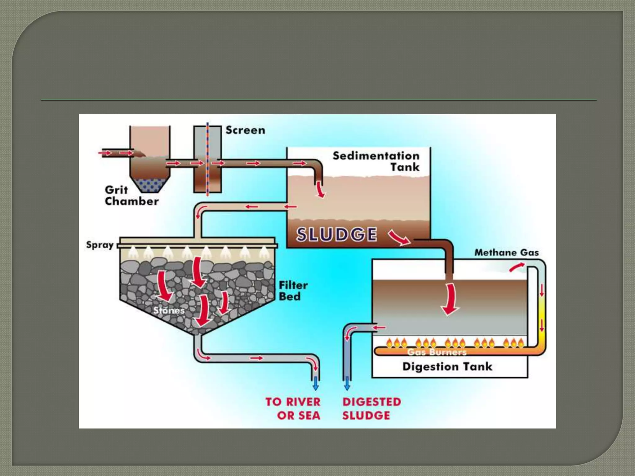
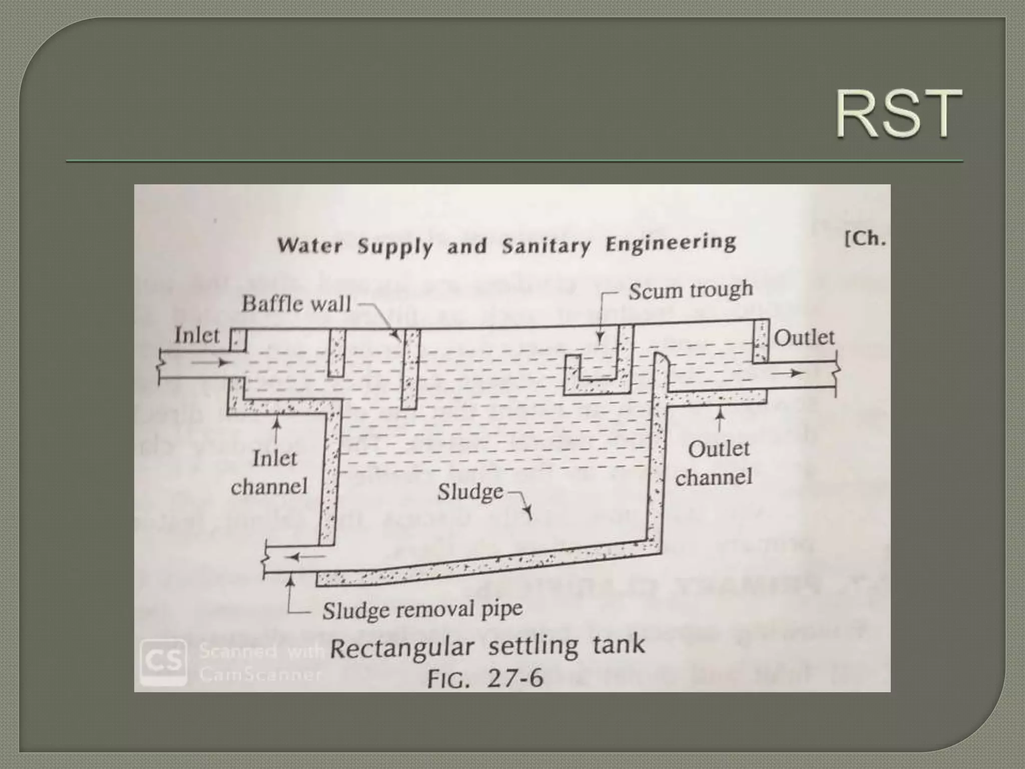
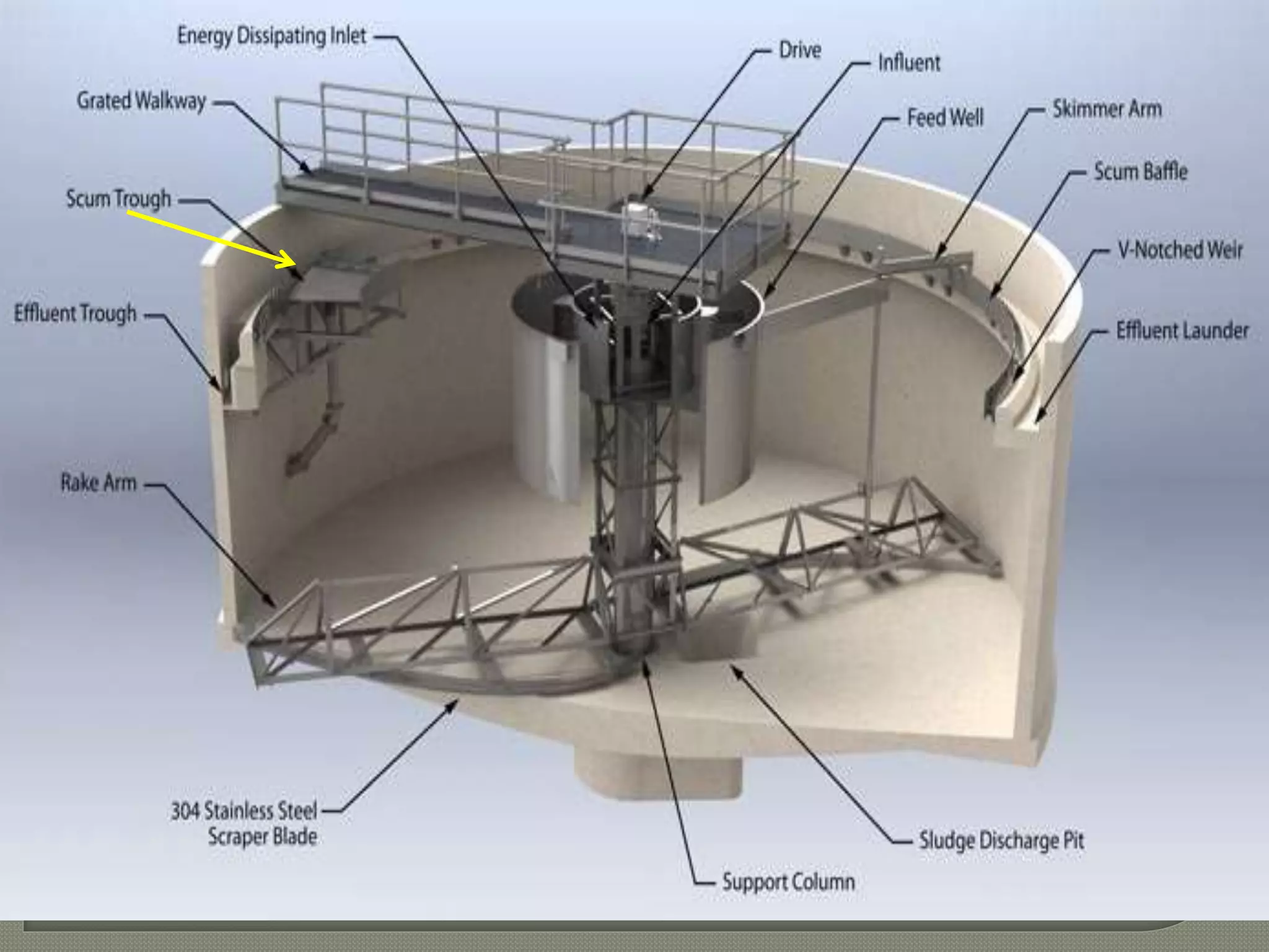
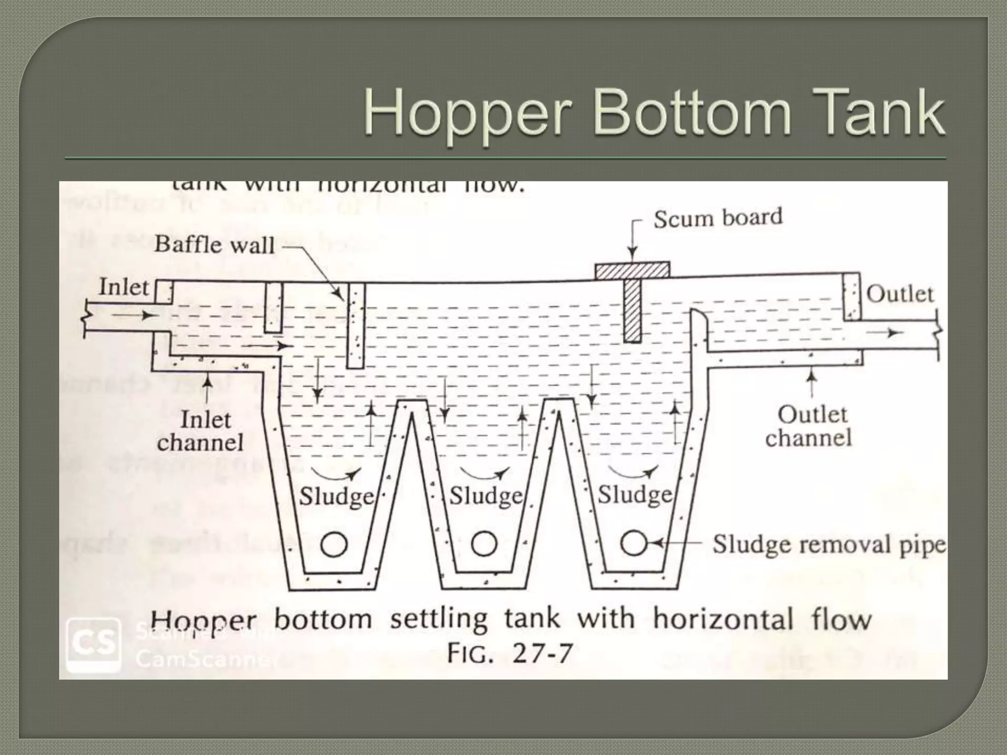
Dr. M. Prasad
Also known as settling tanks or clarifiers
Theory of sedimentation and overall
features are same as water treatment
plants with minor modifications.
As follows..
 The process of sedimentation reduces the strength of
sewage to the extent about 30-35%.
 The quantity o settleable solids in the sewage reduced
up to 80-90%.
 Reduction of BOD up to 30-35%
 Sewage after sedimentation becomes fit for further
treatment works.
Same principle will be applied as in the
water treatments plant.
Sludge : material collected at the bottom of
the sedimentation tank.
Effluent : the partially treated sewage in
sedimentation tanks.
According to the nature of working.
According to the location.
According to the nature of working
1. Fill and draw type
2. Continuous flow type.
Primary clarifiers
Secondary clarifiers.
Primary clarifiers: provided just after the grit
chamber and they have to treat raw
sewage.
Secondary clarifiers: located the after the
secondary treatment units such as filters
and activated sludge process units.
Secondary clarifiers are provided to treat
the treated sewage. They can be treat the
sewage such an extent such that the
effluent can be directly discharged in to
natural waters.
Various aspects of PC….
1. Inlet and outlet arrangements
2. Shape of the tank
3. Capacity of tank
4. Scum baffles
5. Scum removal devices
6. Sludge removal
7. Miscellaneous conditions.
Same as water treatment plants…
Following points should be noted.
 Inflow and out flow rates should be equal
 The flow of sewage should be diffused equally across
the entire section of the tank.
 The flow of outlet should come out as a thin as possible
Rectangular tanks
Circular tanks
Hopper bottom tanks
RT with horizontal flow.
Ratio of length to width is about 4-5
Ratio of width to depth is about 2-3
CT with vertical flow
Fitted with mechanical scrappers
These can be of vertical and horizontal
flow type.
Horizontal type tank..
 Capacity of the tank determined by the
detention period and overflow rate.
 Primary clarifiers designed for 1-3 hrs
detention period
 Overflow rate in primary clarifiers generally
40-50 m3/m2-day.
 Depth not much important but for mechanical
scrappers it should be at least 2 metrs.
Scum baffles are provided in the form of
troughs or boards near the out let to
prevent the entry of floating substances in
to the out let channel
Scum removal devices (SRD)
The primary clarifiers should be provided
with suitable SRD , To remove the floating
material.
This can be collected at the bottom of the
sedimentation tank.
Removed periodically by following
methods
Hand cleaning : obsolete
Hydraulic cleaning: suitable for hopper tank
Mechanical cleaning : suitable for
rectangular tanks
Velocity of flow should be 300 mm/ min
All other arrangements should be made as
per water treatment plant.
 Design a primary clarifier for a town
having population of 34000. The formation
of sewage may be assumed at 150 lpcd.
Assume tank effective depth as 2.5m
Note : overflow rate(SOR) should be b/w
40-50m3/m2-day

Plain sedimentation tanks sewage

  • 1.
  • 3.
    Also known assettling tanks or clarifiers Theory of sedimentation and overall features are same as water treatment plants with minor modifications.
  • 4.
    As follows..  Theprocess of sedimentation reduces the strength of sewage to the extent about 30-35%.  The quantity o settleable solids in the sewage reduced up to 80-90%.  Reduction of BOD up to 30-35%  Sewage after sedimentation becomes fit for further treatment works.
  • 5.
    Same principle willbe applied as in the water treatments plant. Sludge : material collected at the bottom of the sedimentation tank. Effluent : the partially treated sewage in sedimentation tanks.
  • 6.
    According to thenature of working. According to the location. According to the nature of working 1. Fill and draw type 2. Continuous flow type.
  • 7.
    Primary clarifiers Secondary clarifiers. Primaryclarifiers: provided just after the grit chamber and they have to treat raw sewage.
  • 8.
    Secondary clarifiers: locatedthe after the secondary treatment units such as filters and activated sludge process units. Secondary clarifiers are provided to treat the treated sewage. They can be treat the sewage such an extent such that the effluent can be directly discharged in to natural waters.
  • 9.
    Various aspects ofPC…. 1. Inlet and outlet arrangements 2. Shape of the tank 3. Capacity of tank 4. Scum baffles 5. Scum removal devices 6. Sludge removal 7. Miscellaneous conditions.
  • 10.
    Same as watertreatment plants… Following points should be noted.  Inflow and out flow rates should be equal  The flow of sewage should be diffused equally across the entire section of the tank.  The flow of outlet should come out as a thin as possible
  • 11.
  • 12.
    RT with horizontalflow. Ratio of length to width is about 4-5 Ratio of width to depth is about 2-3
  • 13.
    CT with verticalflow Fitted with mechanical scrappers
  • 17.
    These can beof vertical and horizontal flow type. Horizontal type tank..
  • 19.
     Capacity ofthe tank determined by the detention period and overflow rate.  Primary clarifiers designed for 1-3 hrs detention period  Overflow rate in primary clarifiers generally 40-50 m3/m2-day.  Depth not much important but for mechanical scrappers it should be at least 2 metrs.
  • 20.
    Scum baffles areprovided in the form of troughs or boards near the out let to prevent the entry of floating substances in to the out let channel Scum removal devices (SRD) The primary clarifiers should be provided with suitable SRD , To remove the floating material.
  • 21.
    This can becollected at the bottom of the sedimentation tank. Removed periodically by following methods Hand cleaning : obsolete Hydraulic cleaning: suitable for hopper tank Mechanical cleaning : suitable for rectangular tanks
  • 22.
    Velocity of flowshould be 300 mm/ min All other arrangements should be made as per water treatment plant.
  • 23.
     Design aprimary clarifier for a town having population of 34000. The formation of sewage may be assumed at 150 lpcd. Assume tank effective depth as 2.5m Note : overflow rate(SOR) should be b/w 40-50m3/m2-day