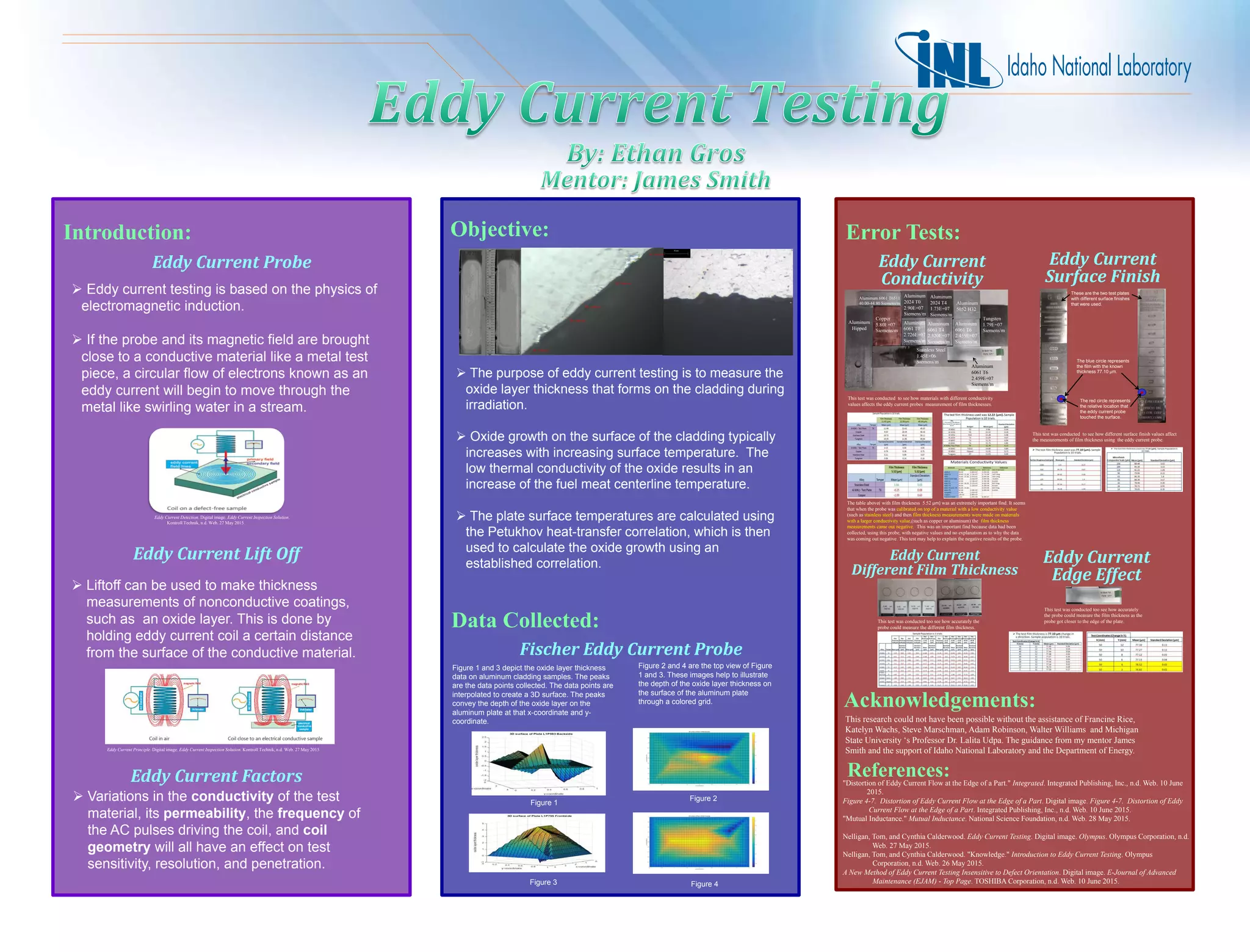
Eddy Current Factors
 Variations in the conductivity of the test
material, its permeability, the frequency of
the AC pulses driving the coil, and coil
geometry will all have an effect on test
sensitivity, resolution, and penetration.
Eddy Current Lift Off
Eddy Current Principle. Digital image. Eddy Current Inspection Solution. Kontroll Technik, n.d. Web. 27 May 2015.
 Eddy current testing is based on the physics of
electromagnetic induction.
 If the probe and its magnetic field are brought
close to a conductive material like a metal test
piece, a circular flow of electrons known as an
eddy current will begin to move through the
metal like swirling water in a stream.
Eddy Current Probe
Eddy Current Detection. Digital image. Eddy Current Inspection Solution.
Kontroll Technik, n.d. Web. 27 May 2015.
 Liftoff can be used to make thickness
measurements of nonconductive coatings,
such as an oxide layer. This is done by
holding eddy current coil a certain distance
from the surface of the conductive material.
 The purpose of eddy current testing is to measure the
oxide layer thickness that forms on the cladding during
irradiation.
 Oxide growth on the surface of the cladding typically
increases with increasing surface temperature. The
low thermal conductivity of the oxide results in an
increase of the fuel meat centerline temperature.
 The plate surface temperatures are calculated using
the Petukhov heat-transfer correlation, which is then
used to calculate the oxide growth using an
established correlation.
Fischer Eddy Current Probe
Introduction: Objective: Error Tests:
Data Collected:
Eddy Current
Conductivity
Eddy Current
Surface Finish
Figure 1 and 3 depict the oxide layer thickness
data on aluminum cladding samples. The peaks
are the data points collected. The data points are
interpolated to create a 3D surface. The peaks
convey the depth of the oxide layer on the
aluminum plate at that x-coordinate and y-
coordinate.
Figure 2 and 4 are the top view of Figure
1 and 3. These images help to illustrate
the depth of the oxide layer thickness on
the surface of the aluminum plate
through a colored grid.
Figure 1
Figure 3
Figure 2
Figure 4
References:"Distortion of Eddy Current Flow at the Edge of a Part." Integrated. Integrated Publishing, Inc., n.d. Web. 10 June
2015.
Figure 4-7. Distortion of Eddy Current Flow at the Edge of a Part. Digital image. Figure 4-7. Distortion of Eddy
Current Flow at the Edge of a Part. Integrated Publishing, Inc., n.d. Web. 10 June 2015.
"Mutual Inductance." Mutual Inductance. National Science Foundation, n.d. Web. 28 May 2015.
Nelligan, Tom, and Cynthia Calderwood. Eddy Current Testing. Digital image. Olympus. Olympus Corporation, n.d.
Web. 27 May 2015.
Nelligan, Tom, and Cynthia Calderwood. "Knowledge." Introduction to Eddy Current Testing. Olympus
Corporation, n.d. Web. 26 May 2015.
A New Method of Eddy Current Testing Insensitive to Defect Orientation. Digital image. E-Journal of Advanced
Maintenance (EJAM) - Top Page. TOSHIBA Corporation, n.d. Web. 10 June 2015.
The blue circle represents
the film with the known
thickness 77.10 µm.
The red circle represents
the relative location that
the eddy current probe
touched the surface.
These are the two test plates
with different surface finishes
that were used.
Copper
5.80E+07
Siemens/m
Aluminum
6061 T6
2.459E+07
Siemens/m
Aluminum
Hipped
Aluminum
6061 T0
2.726E+07
Siemens/m
Stainless Steel
1.45E+06
Siemens/m
Aluminum
6061 T4
2.320E+07
Siemens/m
Aluminum
5052 H32
Aluminum
2024 T0
2.90E+07
Siemens/m
Aluminum
2024 T4
1.73E+07
Siemens/m
Tungsten
1.79E+07
Siemens/m
Aluminum
6061 T6
2.459E+07
Siemens/m
Aluminum 6061 T6511
40.00-44.80 Siemens/m
Acknowledgements:
This research could not have been possible without the assistance of Francine Rice,
Katelyn Wachs, Steve Marschman, Adam Robinson, Walter Williams and Michigan
State University ‘s Professor Dr. Lalita Udpa. The guidance from my mentor James
Smith and the support of Idaho National Laboratory and the Department of Energy.
Eddy Current
Different Film Thickness
This test was conducted to see how materials with different conductivity
values affects the eddy current probes measurement of film thicknesses.
This test was conducted too see how accurately the
probe could measure the different film thickness.
This test was conducted to see how different surface finish values affect
the measurements of film thickness using the eddy current probe.
Eddy Current
Edge Effect
This test was conducted too see how accurately
the probe could measure the film thickness as the
probe got closer to the edge of the plate.
The table above( with film thickness 5.52 µm) was an extremely important find. It seems
that when the probe was calibrated on top of a material with a low conductivity value
(such as stainless steel) and then film thickness measurements were made on materials
with a larger conductivity value,(such as copper or aluminum) the film thickness
measurements came out negative. This was an important find because data had been
collected, using this probe, with negative values and no explanation as to why the data
was coming out negative. This test may help to explain the negative results of the probe.

Poster - Eddy Current Testing

  • 1.
    Eddy Current Factors Variations in the conductivity of the test material, its permeability, the frequency of the AC pulses driving the coil, and coil geometry will all have an effect on test sensitivity, resolution, and penetration. Eddy Current Lift Off Eddy Current Principle. Digital image. Eddy Current Inspection Solution. Kontroll Technik, n.d. Web. 27 May 2015.  Eddy current testing is based on the physics of electromagnetic induction.  If the probe and its magnetic field are brought close to a conductive material like a metal test piece, a circular flow of electrons known as an eddy current will begin to move through the metal like swirling water in a stream. Eddy Current Probe Eddy Current Detection. Digital image. Eddy Current Inspection Solution. Kontroll Technik, n.d. Web. 27 May 2015.  Liftoff can be used to make thickness measurements of nonconductive coatings, such as an oxide layer. This is done by holding eddy current coil a certain distance from the surface of the conductive material.  The purpose of eddy current testing is to measure the oxide layer thickness that forms on the cladding during irradiation.  Oxide growth on the surface of the cladding typically increases with increasing surface temperature. The low thermal conductivity of the oxide results in an increase of the fuel meat centerline temperature.  The plate surface temperatures are calculated using the Petukhov heat-transfer correlation, which is then used to calculate the oxide growth using an established correlation. Fischer Eddy Current Probe Introduction: Objective: Error Tests: Data Collected: Eddy Current Conductivity Eddy Current Surface Finish Figure 1 and 3 depict the oxide layer thickness data on aluminum cladding samples. The peaks are the data points collected. The data points are interpolated to create a 3D surface. The peaks convey the depth of the oxide layer on the aluminum plate at that x-coordinate and y- coordinate. Figure 2 and 4 are the top view of Figure 1 and 3. These images help to illustrate the depth of the oxide layer thickness on the surface of the aluminum plate through a colored grid. Figure 1 Figure 3 Figure 2 Figure 4 References:"Distortion of Eddy Current Flow at the Edge of a Part." Integrated. Integrated Publishing, Inc., n.d. Web. 10 June 2015. Figure 4-7. Distortion of Eddy Current Flow at the Edge of a Part. Digital image. Figure 4-7. Distortion of Eddy Current Flow at the Edge of a Part. Integrated Publishing, Inc., n.d. Web. 10 June 2015. "Mutual Inductance." Mutual Inductance. National Science Foundation, n.d. Web. 28 May 2015. Nelligan, Tom, and Cynthia Calderwood. Eddy Current Testing. Digital image. Olympus. Olympus Corporation, n.d. Web. 27 May 2015. Nelligan, Tom, and Cynthia Calderwood. "Knowledge." Introduction to Eddy Current Testing. Olympus Corporation, n.d. Web. 26 May 2015. A New Method of Eddy Current Testing Insensitive to Defect Orientation. Digital image. E-Journal of Advanced Maintenance (EJAM) - Top Page. TOSHIBA Corporation, n.d. Web. 10 June 2015. The blue circle represents the film with the known thickness 77.10 µm. The red circle represents the relative location that the eddy current probe touched the surface. These are the two test plates with different surface finishes that were used. Copper 5.80E+07 Siemens/m Aluminum 6061 T6 2.459E+07 Siemens/m Aluminum Hipped Aluminum 6061 T0 2.726E+07 Siemens/m Stainless Steel 1.45E+06 Siemens/m Aluminum 6061 T4 2.320E+07 Siemens/m Aluminum 5052 H32 Aluminum 2024 T0 2.90E+07 Siemens/m Aluminum 2024 T4 1.73E+07 Siemens/m Tungsten 1.79E+07 Siemens/m Aluminum 6061 T6 2.459E+07 Siemens/m Aluminum 6061 T6511 40.00-44.80 Siemens/m Acknowledgements: This research could not have been possible without the assistance of Francine Rice, Katelyn Wachs, Steve Marschman, Adam Robinson, Walter Williams and Michigan State University ‘s Professor Dr. Lalita Udpa. The guidance from my mentor James Smith and the support of Idaho National Laboratory and the Department of Energy. Eddy Current Different Film Thickness This test was conducted to see how materials with different conductivity values affects the eddy current probes measurement of film thicknesses. This test was conducted too see how accurately the probe could measure the different film thickness. This test was conducted to see how different surface finish values affect the measurements of film thickness using the eddy current probe. Eddy Current Edge Effect This test was conducted too see how accurately the probe could measure the film thickness as the probe got closer to the edge of the plate. The table above( with film thickness 5.52 µm) was an extremely important find. It seems that when the probe was calibrated on top of a material with a low conductivity value (such as stainless steel) and then film thickness measurements were made on materials with a larger conductivity value,(such as copper or aluminum) the film thickness measurements came out negative. This was an important find because data had been collected, using this probe, with negative values and no explanation as to why the data was coming out negative. This test may help to explain the negative results of the probe.