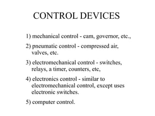
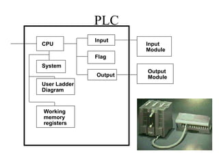
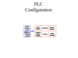
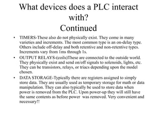
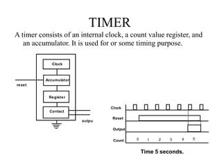
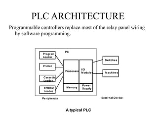
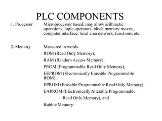
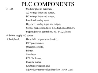
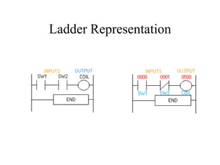
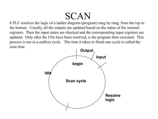
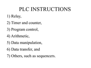
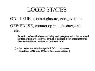
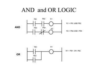
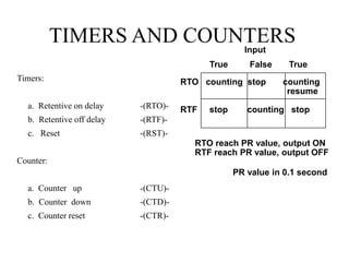
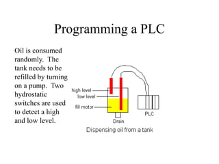
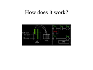
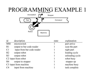
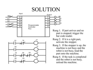
Now a days industries working without PLC & SCADA system is the rarest thing. It is the must learn software and module. In this PPT basic about PLC is given as well as some basic but important programs have performed.
A PLC is a digital operating electronic apparatus.
Which uses a programmable memory for internal storage of instruction for implementing specific function such as logic, sequencing, timing, counting and arithmetic to control through analog or digital input/output modules various types of machines or process.
Techniques to optimize the pagerank algorithm usually fall in two categories. One is to try reducing the work per iteration, and the other is to try reducing the number of iterations. These goals are often at odds with one another. Skipping computation on vertices which have already converged has the potential to save iteration time. Skipping in-identical vertices, with the same in-links, helps reduce duplicate computations and thus could help reduce iteration time. Road networks often have chains which can be short-circuited before pagerank computation to improve performance. Final ranks of chain nodes can be easily calculated. This could reduce both the iteration time, and the number of iterations. If a graph has no dangling nodes, pagerank of each strongly connected component can be computed in topological order. This could help reduce the iteration time, no. of iterations, and also enable multi-iteration concurrency in pagerank computation. The combination of all of the above methods is the STICD algorithm. [sticd] For dynamic graphs, unchanged components whose ranks are unaffected can be skipped altogether.
The Building Blocks of QuestDB, a Time Series Databasejavier ramirez
Talk Delivered at Valencia Codes Meetup 2024-06.
Traditionally, databases have treated timestamps just as another data type. However, when performing real-time analytics, timestamps should be first class citizens and we need rich time semantics to get the most out of our data. We also need to deal with ever growing datasets while keeping performant, which is as fun as it sounds.
It is no wonder time-series databases are now more popular than ever before. Join me in this session to learn about the internal architecture and building blocks of QuestDB, an open source time-series database designed for speed. We will also review a history of some of the changes we have gone over the past two years to deal with late and unordered data, non-blocking writes, read-replicas, or faster batch ingestion.
Adjusting OpenMP PageRank : SHORT REPORT / NOTESSubhajit Sahu
For massive graphs that fit in RAM, but not in GPU memory, it is possible to take
advantage of a shared memory system with multiple CPUs, each with multiple cores, to
accelerate pagerank computation. If the NUMA architecture of the system is properly taken
into account with good vertex partitioning, the speedup can be significant. To take steps in
this direction, experiments are conducted to implement pagerank in OpenMP using two
different approaches, uniform and hybrid. The uniform approach runs all primitives required
for pagerank in OpenMP mode (with multiple threads). On the other hand, the hybrid
approach runs certain primitives in sequential mode (i.e., sumAt, multiply).
Adjusting primitives for graph : SHORT REPORT / NOTESSubhajit Sahu
Graph algorithms, like PageRank Compressed Sparse Row (CSR) is an adjacency-list based graph representation that is
Multiply with different modes (map)
1. Performance of sequential execution based vs OpenMP based vector multiply.
2. Comparing various launch configs for CUDA based vector multiply.
Sum with different storage types (reduce)
1. Performance of vector element sum using float vs bfloat16 as the storage type.
Sum with different modes (reduce)
1. Performance of sequential execution based vs OpenMP based vector element sum.
2. Performance of memcpy vs in-place based CUDA based vector element sum.
3. Comparing various launch configs for CUDA based vector element sum (memcpy).
4. Comparing various launch configs for CUDA based vector element sum (in-place).
Sum with in-place strategies of CUDA mode (reduce)
1. Comparing various launch configs for CUDA based vector element sum (in-place).
Unleashing the Power of Data_ Choosing a Trusted Analytics Platform.pdfEnterprise Wired
In this guide, we'll explore the key considerations and features to look for when choosing a Trusted analytics platform that meets your organization's needs and delivers actionable intelligence you can trust.
2. Agenda
• Review brief history of PLCs and
manufacturing control systems
• Introduce the concepts of discrete control of
manufacturing
• Review the various kinds of instrumentation
used for control.
• Overview ladder logic programming
3. Readings
• Chapter 10 of Computer Aided Manufacturing, Chang,
Chang, T.C. and Wysk, R. A. and Wang, H.P., 3rd Edition,
2006.
4. Exercise
What are some common examples of
control?
Washing machine, sump pump, microwave,
….
Others?
5. Types of control
• Temporal -- control based in time
• State -- control based in state level
• Hybrid – both temporal and state
6. Objectives
• To define the basic components of a PLC
• To apply PLC based control to a
manufacturing system
• To be identify instrumentation required to
implement a PLC control system
• To program a PLC
• To implement a PLC control program and
hardware
7. PURPOSE OF Programmable
Logic Controllers (PLCs)
• Initially designed to replace relay logic
boards
– Sequence device actuation
– Coordinate activities
• Accepts input from a series of switches
• Sends output to devices or relays
9. CONTROL DEVICES
1) mechanical control - cam, governor, etc.,
2) pneumatic control - compressed air,
valves, etc.
3) electromechanical control - switches,
relays, a timer, counters, etc,
4) electronics control - similar to
electromechanical control, except uses
electronic switches.
5) computer control.
12. What devices does a PLC interact
with?
• INPUT RELAYS-(contacts)These are connected to the outside world. They
physically exist and receive signals from switches, sensors, etc. Typically they
are not relays but rather they are transistors.
• INTERNAL UTILITY RELAYS-(contacts) These do not receive signals from
the outside world nor do they physically exist. They are simulated relays and
are what enables a PLC to eliminate external relays. There are also some
special relays that are dedicated to performing only one task. Some are always
on while some are always off. Some are on only once during power-on and are
typically used for initializing data that was stored.
• COUNTERS-These again do not physically exist. They are simulated counters
and they can be programmed to count pulses. Typically these counters can
count up, down or both up and down. Since they are simulated they are limited
in their counting speed. Some manufacturers also include high-speed counters
that are hardware based. We can think of these as physically existing. Most
times these counters can count up, down or up and down.
13. What devices does a PLC interact
with?
Continued
• TIMERS-These also do not physically exist. They come in many
varieties and increments. The most common type is an on-delay type.
Others include off-delay and both retentive and non-retentive types.
Increments vary from 1ms through 1s.
• OUTPUT RELAYS-(coils)These are connected to the outside world.
They physically exist and send on/off signals to solenoids, lights, etc.
They can be transistors, relays, or triacs depending upon the model
chosen.
• DATA STORAGE-Typically there are registers assigned to simply
store data. They are usually used as temporary storage for math or data
manipulation. They can also typically be used to store data when
power is removed from the PLC. Upon power-up they will still have
the same contents as before power was removed. Very convenient and
necessary!!
15. TERMS
Throw - number of states
Pole - number of connecting moving parts (number of individual circuits).
SPDT
DPST
A serial switch box (A-B box) has
two 25 pin serial ports to switch from.
Input
Output
A B
Knob
How is this switch classified?
16. TYPES OF SWITCHES
1. Basic switch, operated by a mechanical level,
2. Push-button switch,
3. Slide switch,
4. Thumbwheel switch,
5. Limit switch,
6. Proximity switch, and
7. Photoelectric switch.
RATING: voltage, current
17. RELAYS
A switch whose operation is activated by an electromagnet is called a "relay"
contact
coil
input
Relay coil Output contact
18. COUNTER
Digital counters output in the form of a relay contact when a
preassigned count value is reached.
Register
Accumulator
contact
input
reset
output
Input
Reset
Output
Count 0 1 2 3 4 5 0 1
5
19. TIMER
A timer consists of an internal clock, a count value register, and
an accumulator. It is used for or some timing purpose.
Clock
Accumulator
contact
reset
output
Register
Contact
Time 5 seconds.
Clock
Reset
Output
Count 1 2 3 4
0 5
20. AN EXAMPLE OF RELAY LOGIC
L1
LS1 PB1 LS2 R1
R1
R1
TIMER
R2
PR=5
For process control, it is desired to have the process start (by turning on a motor) five
seconds after a part touches a limit switch. The process is terminated automatically
when the finished part touches a second limit switch. An emergency switch will stop
the process any time when it is pushed.
LS1
PB1
LS2
R1
TIMER
5
Motor
R2
21. PLC ARCHITECTURE
Programmable controllers replace most of the relay panel wiring
by software programming.
Processor
I/O
M odules
M emory
Power
Supply
Program
Loader
Printer
Cassette
Loader
EPROM
Loader
Switches
M achines
Peripherals External Devices
PC
A typical PLC
22. PLC COMPONENTS
1. Processor Microprocessor based, may allow arithmetic
operations, logic operators, block memory moves,
computer interface, local area network, functions, etc.
2. Memory Measured in words.
ROM (Read Only Memory),
RAM (Random Access Memory),
PROM (Programmable Read Only Memory),
EEPROM (Electronically Erasable Programmable
ROM),
EPROM (Erasable Programmable Read Only Memory),
EAPROM (Electronically Alterable Programmable
Read Only Memory), and
Bubble Memory.
23. PLC COMPONENTS
3. I/O Modular plug-in periphery
AC voltage input and output,
DC voltage input and output,
Low level analog input,
High level analog input and output,
Special purpose modules, e.g.., high speed timers,
Stepping motor controllers, etc. PID, Motion
4. Power supply AC power
5. Peripheral Hand held programmer (loader),
CRT programmer,
Operator console,
Printer,
Simulator,
EPROM loader,
Cassette loader,
Graphics processor, and
Network communication interface. MAP, LAN
24. LADDER DIAGRAM
A ladder diagram (also called contact symbology) is a means of
graphically representing the logic required in a relay logic
system.
A
R1
PB1 PB2
R1
R1
start emergency stop
Rail
Rung
27. SCAN
begin
Input
Output
Resolve
logic
Idle
A PLC resolves the logic of a ladder diagram (program) rung by rung, from the top to
the bottom. Usually, all the outputs are updated based on the status of the internal
registers. Then the input states are checked and the corresponding input registers are
updated. Only after the I/Os have been resolved, is the program then executed. This
process is run in a endless cycle. The time it takes to finish one cycle is called the
scan time.
Scan cycle
28. PLC INSTRUCTIONS
1) Relay,
2) Timer and counter,
3) Program control,
4) Arithmetic,
5) Data manipulation,
6) Data transfer, and
7) Others, such as sequencers.
29. LOGIC STATES
ON : TRUE, contact closure, energize, etc.
OFF: FALSE, contact open , de-energize,
etc.
(In the notes we use the symbol "~" to represent
negation. AND and OR are logic operators. )
Do not confuse the internal relay and program with the external
switch and relay. Internal symbols are used for programming.
External devices provide actual interface.
30. AND and OR LOGIC
PB1 R1
PB2
R2
R1 = PB1.AND.PB2
R2 = PB2.AND.~PB4
PB3 PB4
PB1 R1
PB2
R1 = PB1 .OR. PB2
AND
OR
31. COMBINED AND & OR
R1 = PB1 .OR. (PB2 .AND. PB3)
PB1 R1
PB2 pb3
32. RELAY
A Relay consists of two parts, the coil and the contact(s).
Contacts:
a. Normally open -| |-
b. Normally closed -|/|-
c. Off-on transitional -||-
d. On-off transitional -| |-
Coil:
a. Energize Coil -( )-
b. De-energize -(/)-
c. Latch -(L)-
d. Unlatch -(U)-
( )
33. TIMERS AND COUNTERS
Timers:
a. Retentive on delay -(RTO)-
b. Retentive off delay -(RTF)-
c. Reset -(RST)-
Counter:
a. Counter up -(CTU)-
b. Counter down -(CTD)-
c. Counter reset -(CTR)-
RTO counting stop counting
resume
RTF stop counting stop
True False True
Input
RTO reach PR value, output ON
RTF reach PR value, output OFF
PR value in 0.1 second
34. SEQUENCER
Sequencers are used with machines or processes involving
repeating operating cycles which can be segmented into
steps.
Output
Step A B C Dwell time
1 ON OFF OFF 5 sec.
2 ON ON OFF 10 sec.
3 OFF OFF ON 3 sec.
4 OFF ON OFF 9 sec.
35. Rockwell/ Allen Bradley PLC
I/O points are numbered, they correspond to the I/O slot on
the PLC.
For A-B controller used in our lab
I/O uses 1-32
Internal relays use 033 - 098
Internal timers/counters/sequencers use 901-932
Status 951-982
36. Programming a PLC
Oil is consumed
randomly. The
tank needs to be
refilled by turning
on a pump. Two
hydrostatic
switches are used
to detect a high
and low level.
40. PROGRAMMING EXAMPLE 1
Part
microswitch
Bar code reader
Stopper
Conveyor
Machine
Robot
id description state explanation
MSI microswitch 1 part arrive
R1 output to bar code reader 1 scan the part
C1 input from bar code reader 1 right part
R2 output robot 1 loading cycle
R3 output robot 1 unloading cycle
C2 input from robot 1 robot busy
R4 output to stopper 1 stopper up
C3 input from machine 1 machine busy
C4 input from machine 1 task complete