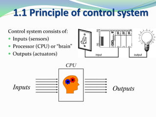
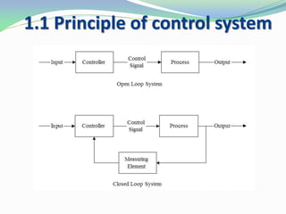
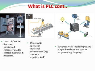
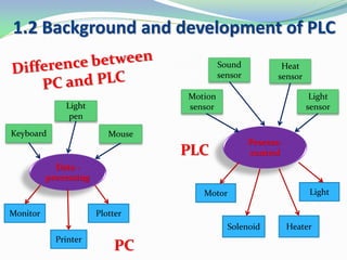
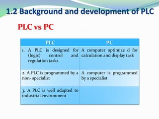
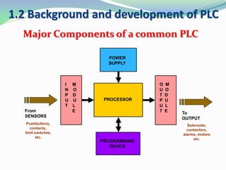
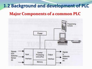
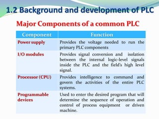
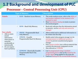
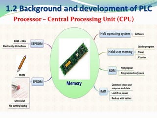
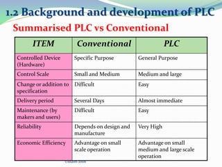
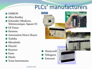
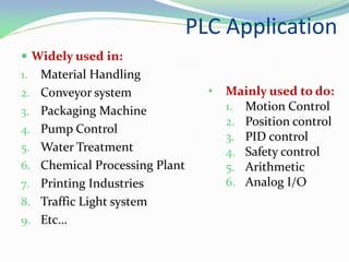
• Principle of Control System
• Background and Development of PLC
• Advantages and Disadvantages
• Types of PLC
• PLC Operation
• Application of PLC
• Define the PLC, List the advantages and
disadvantages of PLCLO1
• Identify the main components of PLC
system and its functionsLO2
• Explain the basic sequence of PLC
operation, Identify and differentiate the
types of PLC.
LO3
1.1 Principle of control system
Control system consists of:
 Inputs (sensors)
 Processor (CPU) or “brain”
 Outputs (actuators)
Inputs Outputs
CPU
1.1 Principle of control system
Input signals:
• usually come from various sensors that
convert physical quantities into electrical
signals. These sensors may be simple push-
button switches, limit switches or
proximity sensors, etc.
• Depending on the sensor uses this
information may be an on/off(binary) or a
continuous (analogue) representation of
the input quantity
1.1 Principle of control system
Processor:
• From the input signals the automatic
control system has to produce the
necessary output signal in accordance to
the control plant built into the processor.
• The control plant can be implemented into
two different ways, using either hard –
wired control system or programmable
control system.
• Hard-wired control systems have the
control function fixed permanently when
the system components are connected
together (eg. Electrically).
• Programmable control system the control
function is programmed and stored within
a memory unit. This program can be
changed or modified when necessary.
Hard-wired
Relay
Electronic logic
Pneumatic logic
Hydraulic logic
Programmable
Computer
Microprocessor
Microcontroller
Programmable
Logic Controller
(PLC)
1.1 Principle of control system
Output:
• Motors, cylinders, relays, etc. are the
output devices which convert signals from
the control system into other necessary
quantities.
• Example: A pneumatic cylinder, converts
pneumatic signals into linear motion.
1.2 Background and development of PLC
Introduction:
• The PLC was introduced
around 1969 largely as a
result of specifications
written by the General
Motors Corporation.
• Developed to offer the
same functionality as the
existing relay logic
systems
1.2 Background and development of PLC
Development of programmable controller
Year Development
1968 Programmable concept was developed
1969 Hardware CPU controller, with logic instructions, 1 K of memory
and 128 I/O points.
1974 Use of several (multi) processors within a PLC - timers and
counters; arithmetic operations; 12 K of memory and 1024 I/O
points.
1977 Microprocessors - based PLC introduced
1980 • Intelligent I/O modules developed
• Enhanced communications facilities
• Enhanced software features (e.g. documentation)
• Use of personal microcomputers as programming aids
1983 Low - cost small PLC’s introduced
1985 Networking of all levels of PLC, computer and machine using
SCADA software.
1.2 Background and development of PLC
• A digitally operating electronic apparatus which uses
programming memory for the internal storage of
instructions for implementing specific functions such as
logic, sequencing, timing, counting and arithmetic to
control through digital or analog modules, various types
of machines or process.
National Electrical Manufacturer
Association
What is PLC cont..
 In an automated system, the PLC is commonly
regarded as the heart of the control system.
 The PLC may used to control a simple and repetitive
task.
 Or a few of them may be interconnected together with
other controller or host computer through a sort of
communication network, in order to integrate the
control in a complex process.
1.2 Background and development of PLC
What is PLC cont..
 Heart of Control
System a
specialized
computer used to
control machines &
processes.
 Designed to
operate in
industrial
environment (e.g:
control a
repetitive task)
 Equipped with special input and
output interfaces and control
programming language.
1.2 Background and development of PLC
Process-
control
Keyboard
Light
pen
Mouse
Monitor Plotter
Printer
Data -
processing
Motion
sensor
Sound
sensor
Heat
sensor
Light
sensor
Motor
Solenoid
Light
Heater
PC
PLC
PLC vs PC
1.2 Background and development of PLC
PLC PC
1. A PLC is designed for
(logic) control and
regulation tasks
A computer optimize d for
calculation and display task
2. A PLC is programmed by a
non- specialist
A computer is programmed
by a specialist
3. A PLC is well adapted to
industrial environment
1.2 Background and development of PLC
Major Components of a common PLC
PROCESSOR
POWER
SUPPLY
I M
N O
P D
U U
T L
E
O M
U O
T D
P U
U L
T E
PROGRAMMING
DEVICE
From
SENSORS
Pushbuttons,
contacts,
limit switches,
etc.
To
OUTPUT
Solenoids,
contactors,
alarms, motors
etc.
1.2 Background and development of PLC
Major Components of a common PLC
1.2 Background and development of PLC
Major Components of a common PLC
Component Function
Power supply Provides the voltage needed to run the
primary PLC components
I/O modules Provides signal conversion and isolation
between the internal logic-level signals
inside the PLC and the field’s high level
signal.
Processor (CPU) Provides intelligence to command and
govern the activities of the entire PLC
systems.
Programmable
devices
Used to enter the desired program that will
determine the sequence of operation and
control of process equipment or driven
machine.
1.2 Background and development of PLC
Processor – Central Processing Unit (CPU)
• The processor module contains
• PLC’s microprocessor
• Supporting circuitry
• Memory system
• The main function of the microprocessor is to
analyse data coming from field sensors through input
modules, make decisions based on the user’s defined
control program and return signal back through output
modules to the field devices. Field sensors: switches,
flow, level, pressure, temp. transmitters, etc. Field output
devices: motors, valves, solenoids, lamps, or audible
devices.
• The memory system in the processor module has two
parts: a system memory and an application memory
1.2 Background and development of PLC
Processor – Central Processing Unit (CPU)
• System memory includes an area called the EXECUTIVE,
composed of permanently-stored programs that direct all system
activities, such as execution of the users control program,
communication with peripheral devices, and other system
activities.
•The system memory also contains the routines that implement
the PLC’s instruction set, which is composed of specific control
functions such as logic, sequencing, timing, counting, and
arithmetic.
•System memory is generally built from read-only memory
devices.
•The application memory is divided into the data table area and
user program area.
•The data table stores any data associated with the user’s control
program, such as system input and output status data, and any
stored constants, variables, or preset values. The data table is
where data is monitored, manipulated, and changed for control
purposes.
•The user program area is where the programmed instructions
entered by the user are stored as an application control program.
SYSTEM
APPLICATION
•Data Table
•User Program
Memory
Mapping
Organisation
1.2 Background and development of PLC
Processor – Central Processing Unit (CPU)
Type of Memory Description
Volatile • RAM – Random Access Memory • The words random access refer to the ability of
any location (address) in the memory to be
accessed or used.
• Must have battery backup to retain or protect
the stored program
Non-volatile
• Able to retain
stored
information
when power is
removed,
accidentally or
intentionally
• Do not require
back-up battery
• ROM – Read Only Memory • Read only indicates that the information stored
in memory can be read only and cannot be
changed
• PROM – Programmable Read
Only Memory
• Allows initial and/or additional information to
be written into the chip
• EPROM – Erasable
Programmable Read On Memory
• Ideally suited when program storage is to be
semi-permanent or additional security is
needed to prevent unauthorized program
changes
• Has a quartz window over a silicon material that
contains the electronic integrated circuits
• Also referred as UVPROM
• EEPROM – Electrically Erasable
Programmable Read Only
Memory
• Can be programmed using a standard
programming device and can be erased by the
proper signal being applied to the erase pin
• Used as a backup for the normal RAM memory
1.2 Background and development of PLC
Processor – Central Processing Unit (CPU)
1.2 Background and development of PLC
I/O Modules
• The I/O interface section of a PLC connects it to
external field devices.
• The main purpose of the I/O interface is to condition the
various signals received from or sent to the external input and
output devices.
• Input modules converts signals from discrete or analog input
devices to logic levels acceptable to PLC’s processor.
• Output modules converts signal from the processor to levels
capable of driving the connected discrete or analog output
devices.
• Manual Input
– Switches
– Pushbuttons
– Keyboard
– Barcode reader
• Sensing Devices
– Limit Switches
– Photoelectric Sensors
– Proximity Sensors
– Condition Sensors
• Pressure Switches
• Level Switches
• Temperature Switches
• Vacuum Switches
• Float Switches
• Encoders
I/O Modules: Input
1.2 Background and development of PLC
• Valves
• Motor Starters
• Solenoids
• Actuators
• Control Relays
• Horns & Alarms
• Stack Lights
• Fans
• Counter
• Buzzer
• Alarm
• Pumps
• Printers
I/O Modules: Output
1.2 Background and development of PLC
Programming Device
• Types
– Hand held unit with LED / LCD
display
– Desktop type with a CRT display
– Compatible computer terminal
• Also known as:
– Industrial Terminal ( Allen
Bradley )
– Program Development Terminal
( General Electric )
– Programming Panel ( Gould
Modicon )
– Programmer ( Square D )
– Program Loader ( Idec-Izumi )
– Programming Console (
Keyence / Omron )
1.2 Background and development of PLC
PLC Operation (Scan Time)
• The process of reading the
inputs, executing the program
and updating the outputs is
knows as scan.
• The scan time is normally a
continuous and sequentially
process of reading the status of
inputs, evaluating the control
logic and updating outputs.
• Scan time specification
indicates how fast the controller
can react to the field inputs and
correctly solve the control logic.
PHASE 2
Program
Execution
PHASE 3
Output
Scan
PHASE 1
Read Inputs
Scan
1. CHECK INPUT STATUS
 First the PLC takes a look at each input to determine if it is on
or off. In other words, is the sensor connected to the first
input on? How about the second input? How about the
third... It records this data into its memory to be us
2. EXECUTE PROGRAM
 Next the PLC executes your program one instruction at a
time. Maybe your program said that if the first input was on
then it should turn on the first output. Since it already knows
which inputs are on/off from the previous step it will be able
to decide whether the first output should be turned on based
on the state of the first input. It will store the execution
results for use later during the next step.
©snaim 2008
1.2 Background and development of PLC
PLC Operation (Scan Time)
PLC Operation(Scan time)
3. UPDATE OUTPUT STATUS
 Finally the PLC updates the status of the outputs. It
updates the outputs based on which inputs were on
during the first step and the results of executing your
program during the second step. Based on the example
in step 2 it would now turn on the first output because
the first input was on and your program said to turn on
the first output when this condition is true.
©snaim 2008
Check i/p Status Execute Program Update o/p Status
1.2 Background and development of PLC
PLC Operation (Scan Time)
Factors influencing Scan Time
 The time required to make a single scan varies from 0.1
ms up to 10 ms depending on its CPU processing speed
and the length of the user program.
 The user of remote I/O subsystem increase the scan
time as a results of having to transmit the I/O update
the remote subsystem.
 Monitoring of the control program also adds overhead
time to the scan, as the controller’s CPU has to send
the status of coils and contact to the CRT or other
monitoring devices.
1.2 Background and development of PLC
What PLC Can Do
CONTROL TYPE FUNCTIONS
Sequences Control •Conventional Relay Control Logic Replacer
/P.C.B Card Controller Replacer
•Timers/Counters
•Auto/Semi-auto/Manual Control of machine
and Processes
Sophisticated Control /
Regulatory Control
•Arithmetic Operation
•Information handling
•Analog Control (Temperature, Pressure)
•P.I.D (Proportional-Integral-Derivation)
•Servo Motor and Stepper Motor
Supervisory Control •Process Monitoring and Alarm
•Fault Diagnostic and Monitoring
•Interfacing with Computer -Printer/ASCII
•Factory Automation
•Local Area Network / Wide Area Network
Conventional Control Panel (Hard-wired) and its
difficulties
 Beginning of industrial
revolution, in 1960 & 1970
automated machines were
controlled by
electromechanical relays.
 Relays were all hardwired
together inside control
panel.
 Conventional relay control
panel is very inflexible.
1.2 Background and development of PLC
 There is to much wiring work in the panel.
 Modification can be quite difficult.
 Troubleshooting can be quite troublesome as you may
require a skillful person.
 Power consumption can be quite high as the coil
consumer power.
 Machine downtime is usually long when problem
occur, as it take long time to trouble shooting.
Disadvantages of Conventional Control Panel
1.2 Background and development of PLC
Advantages of PLC
1.2 Background and development of PLC
 The wiring of the system usually reduces by 80%.
 Power consumption greatly reduced as PLC consume
much less power.
 The PLC self-diagnostic function enable easy and fast
troubleshooting of the system.
 Modification of the control sequence or application
can easily be done by programming through the
console or computer software without changing of I/O
wiring.
1.2 Background and development of PLC
Advantages of PLC
 In PLC system, spare parts for relays and hardware
timers are greatly reduced as compared to
conventional control panel.
 The machine cycle time is improve due to the speed of
PLC operation is in millisecond.
 It cost much less compared to conventional system in
situation when the number of I/Os is very large and
control function are complex.
 The reliability is high an easily maintenance.
1.2 Background and development of PLC
Advantages of PLC
 Most PLCs manufacturers offer only closed architectures
for their products .
 PLC devices are proprietary, which means that parts and
software from one manufacturer can ‘t easily be used in
combination with parts of another manufacturer, which
limits the design and cost options.
 PLC were Designed for Relay Logic Ladder and have
Difficulty with some Smart Devices.
 To maximize PLC performance and Flexibility, a number of
Optional Modules must be added
1.2 Background and development of PLC
Disadvantages of PLC
PLC vs Conventional
1.2 Background and development of PLC
Conventonal control PLC
• The functions are determined by the
physical wiring.
• The functions are determined
by a program stored in the
memory.
• Changing the function means
changing the wiring.
• The control functions can be
changed simply by changing the
program.
• Can be contact-making type (relays,
contactors) or electronic type (logic
circuits)
• Consist of a control device, to
which all the sensors and
actuators are connected.
ITEM Conventional PLC
Controlled Device
(Hardware)
Specific Purpose General Purpose
Control Scale Small and Medium Medium and large
Change or addition to
specification
Difficult Easy
Delivery period Several Days Almost immediate
Maintenance (by
makers and users)
Difficult Easy
Reliability Depends on design and
manufacture
Very High
Economic Efficiency Advantage on small
scale operation
Advantage on small
medium and large scale
operation
©snaim 2008
Summarised PLC vs Conventional
1.2 Background and development of PLC
PLCs’ manufacturers
OMRON
Allen Bradley
Schneider (Modicon,
Telemecanique, Square D)
GE Fanuc
Siemens
Automation Direct (Koyo)
Toshiba
Mitsubishi
Hitachi
Keyence
Festo
Eberle
Texas Instruments
©snaim 2008
Honeywell
Yokogawa
Emerson
PLC Application
 Widely used in:
1. Material Handling
2. Conveyor system
3. Packaging Machine
4. Pump Control
5. Water Treatment
6. Chemical Processing Plant
7. Printing Industries
8. Traffic Light system
9. Etc…
• Mainly used to do:
1. Motion Control
2. Position control
3. PID control
4. Safety control
5. Arithmetic
6. Analog I/O
Any question?
Suppose can answer the following questions:
 When the PLC was developed?
 What is PLC?
 What are the major components of PLC and its
functions?
 How the PLC works?
 What are advantages and disadvantages of PLC?
 What are the difference between PLC control and
conventional control?
 Where are the PLC can be used?
 What are the PLC leading brands
What have you learned today?

Chapter 1

  • 2.
    • Principle ofControl System • Background and Development of PLC • Advantages and Disadvantages • Types of PLC • PLC Operation • Application of PLC
  • 3.
    • Define thePLC, List the advantages and disadvantages of PLCLO1 • Identify the main components of PLC system and its functionsLO2 • Explain the basic sequence of PLC operation, Identify and differentiate the types of PLC. LO3
  • 4.
    1.1 Principle ofcontrol system Control system consists of:  Inputs (sensors)  Processor (CPU) or “brain”  Outputs (actuators) Inputs Outputs CPU
  • 5.
    1.1 Principle ofcontrol system
  • 6.
    1.1 Principle ofcontrol system Input signals: • usually come from various sensors that convert physical quantities into electrical signals. These sensors may be simple push- button switches, limit switches or proximity sensors, etc. • Depending on the sensor uses this information may be an on/off(binary) or a continuous (analogue) representation of the input quantity
  • 7.
    1.1 Principle ofcontrol system Processor: • From the input signals the automatic control system has to produce the necessary output signal in accordance to the control plant built into the processor. • The control plant can be implemented into two different ways, using either hard – wired control system or programmable control system. • Hard-wired control systems have the control function fixed permanently when the system components are connected together (eg. Electrically). • Programmable control system the control function is programmed and stored within a memory unit. This program can be changed or modified when necessary. Hard-wired Relay Electronic logic Pneumatic logic Hydraulic logic Programmable Computer Microprocessor Microcontroller Programmable Logic Controller (PLC)
  • 8.
    1.1 Principle ofcontrol system Output: • Motors, cylinders, relays, etc. are the output devices which convert signals from the control system into other necessary quantities. • Example: A pneumatic cylinder, converts pneumatic signals into linear motion.
  • 9.
    1.2 Background anddevelopment of PLC Introduction: • The PLC was introduced around 1969 largely as a result of specifications written by the General Motors Corporation. • Developed to offer the same functionality as the existing relay logic systems
  • 10.
    1.2 Background anddevelopment of PLC Development of programmable controller Year Development 1968 Programmable concept was developed 1969 Hardware CPU controller, with logic instructions, 1 K of memory and 128 I/O points. 1974 Use of several (multi) processors within a PLC - timers and counters; arithmetic operations; 12 K of memory and 1024 I/O points. 1977 Microprocessors - based PLC introduced 1980 • Intelligent I/O modules developed • Enhanced communications facilities • Enhanced software features (e.g. documentation) • Use of personal microcomputers as programming aids 1983 Low - cost small PLC’s introduced 1985 Networking of all levels of PLC, computer and machine using SCADA software.
  • 11.
    1.2 Background anddevelopment of PLC • A digitally operating electronic apparatus which uses programming memory for the internal storage of instructions for implementing specific functions such as logic, sequencing, timing, counting and arithmetic to control through digital or analog modules, various types of machines or process. National Electrical Manufacturer Association
  • 12.
    What is PLCcont..  In an automated system, the PLC is commonly regarded as the heart of the control system.  The PLC may used to control a simple and repetitive task.  Or a few of them may be interconnected together with other controller or host computer through a sort of communication network, in order to integrate the control in a complex process. 1.2 Background and development of PLC
  • 13.
    What is PLCcont..  Heart of Control System a specialized computer used to control machines & processes.  Designed to operate in industrial environment (e.g: control a repetitive task)  Equipped with special input and output interfaces and control programming language.
  • 14.
    1.2 Background anddevelopment of PLC Process- control Keyboard Light pen Mouse Monitor Plotter Printer Data - processing Motion sensor Sound sensor Heat sensor Light sensor Motor Solenoid Light Heater PC PLC
  • 15.
    PLC vs PC 1.2Background and development of PLC PLC PC 1. A PLC is designed for (logic) control and regulation tasks A computer optimize d for calculation and display task 2. A PLC is programmed by a non- specialist A computer is programmed by a specialist 3. A PLC is well adapted to industrial environment
  • 16.
    1.2 Background anddevelopment of PLC Major Components of a common PLC PROCESSOR POWER SUPPLY I M N O P D U U T L E O M U O T D P U U L T E PROGRAMMING DEVICE From SENSORS Pushbuttons, contacts, limit switches, etc. To OUTPUT Solenoids, contactors, alarms, motors etc.
  • 17.
    1.2 Background anddevelopment of PLC Major Components of a common PLC
  • 18.
    1.2 Background anddevelopment of PLC Major Components of a common PLC Component Function Power supply Provides the voltage needed to run the primary PLC components I/O modules Provides signal conversion and isolation between the internal logic-level signals inside the PLC and the field’s high level signal. Processor (CPU) Provides intelligence to command and govern the activities of the entire PLC systems. Programmable devices Used to enter the desired program that will determine the sequence of operation and control of process equipment or driven machine.
  • 19.
    1.2 Background anddevelopment of PLC Processor – Central Processing Unit (CPU) • The processor module contains • PLC’s microprocessor • Supporting circuitry • Memory system • The main function of the microprocessor is to analyse data coming from field sensors through input modules, make decisions based on the user’s defined control program and return signal back through output modules to the field devices. Field sensors: switches, flow, level, pressure, temp. transmitters, etc. Field output devices: motors, valves, solenoids, lamps, or audible devices. • The memory system in the processor module has two parts: a system memory and an application memory
  • 20.
    1.2 Background anddevelopment of PLC Processor – Central Processing Unit (CPU) • System memory includes an area called the EXECUTIVE, composed of permanently-stored programs that direct all system activities, such as execution of the users control program, communication with peripheral devices, and other system activities. •The system memory also contains the routines that implement the PLC’s instruction set, which is composed of specific control functions such as logic, sequencing, timing, counting, and arithmetic. •System memory is generally built from read-only memory devices. •The application memory is divided into the data table area and user program area. •The data table stores any data associated with the user’s control program, such as system input and output status data, and any stored constants, variables, or preset values. The data table is where data is monitored, manipulated, and changed for control purposes. •The user program area is where the programmed instructions entered by the user are stored as an application control program. SYSTEM APPLICATION •Data Table •User Program Memory Mapping Organisation
  • 21.
    1.2 Background anddevelopment of PLC Processor – Central Processing Unit (CPU) Type of Memory Description Volatile • RAM – Random Access Memory • The words random access refer to the ability of any location (address) in the memory to be accessed or used. • Must have battery backup to retain or protect the stored program Non-volatile • Able to retain stored information when power is removed, accidentally or intentionally • Do not require back-up battery • ROM – Read Only Memory • Read only indicates that the information stored in memory can be read only and cannot be changed • PROM – Programmable Read Only Memory • Allows initial and/or additional information to be written into the chip • EPROM – Erasable Programmable Read On Memory • Ideally suited when program storage is to be semi-permanent or additional security is needed to prevent unauthorized program changes • Has a quartz window over a silicon material that contains the electronic integrated circuits • Also referred as UVPROM • EEPROM – Electrically Erasable Programmable Read Only Memory • Can be programmed using a standard programming device and can be erased by the proper signal being applied to the erase pin • Used as a backup for the normal RAM memory
  • 22.
    1.2 Background anddevelopment of PLC Processor – Central Processing Unit (CPU)
  • 23.
    1.2 Background anddevelopment of PLC I/O Modules • The I/O interface section of a PLC connects it to external field devices. • The main purpose of the I/O interface is to condition the various signals received from or sent to the external input and output devices. • Input modules converts signals from discrete or analog input devices to logic levels acceptable to PLC’s processor. • Output modules converts signal from the processor to levels capable of driving the connected discrete or analog output devices.
  • 24.
    • Manual Input –Switches – Pushbuttons – Keyboard – Barcode reader • Sensing Devices – Limit Switches – Photoelectric Sensors – Proximity Sensors – Condition Sensors • Pressure Switches • Level Switches • Temperature Switches • Vacuum Switches • Float Switches • Encoders I/O Modules: Input 1.2 Background and development of PLC
  • 25.
    1.2 Background anddevelopment of PLC
  • 26.
    • Valves • MotorStarters • Solenoids • Actuators • Control Relays • Horns & Alarms • Stack Lights • Fans • Counter • Buzzer • Alarm • Pumps • Printers I/O Modules: Output 1.2 Background and development of PLC
  • 27.
    1.2 Background anddevelopment of PLC
  • 28.
    1.2 Background anddevelopment of PLC Programming Device • Types – Hand held unit with LED / LCD display – Desktop type with a CRT display – Compatible computer terminal • Also known as: – Industrial Terminal ( Allen Bradley ) – Program Development Terminal ( General Electric ) – Programming Panel ( Gould Modicon ) – Programmer ( Square D ) – Program Loader ( Idec-Izumi ) – Programming Console ( Keyence / Omron )
  • 29.
    1.2 Background anddevelopment of PLC PLC Operation (Scan Time) • The process of reading the inputs, executing the program and updating the outputs is knows as scan. • The scan time is normally a continuous and sequentially process of reading the status of inputs, evaluating the control logic and updating outputs. • Scan time specification indicates how fast the controller can react to the field inputs and correctly solve the control logic. PHASE 2 Program Execution PHASE 3 Output Scan PHASE 1 Read Inputs Scan
  • 30.
    1. CHECK INPUTSTATUS  First the PLC takes a look at each input to determine if it is on or off. In other words, is the sensor connected to the first input on? How about the second input? How about the third... It records this data into its memory to be us 2. EXECUTE PROGRAM  Next the PLC executes your program one instruction at a time. Maybe your program said that if the first input was on then it should turn on the first output. Since it already knows which inputs are on/off from the previous step it will be able to decide whether the first output should be turned on based on the state of the first input. It will store the execution results for use later during the next step. ©snaim 2008 1.2 Background and development of PLC PLC Operation (Scan Time)
  • 31.
    PLC Operation(Scan time) 3.UPDATE OUTPUT STATUS  Finally the PLC updates the status of the outputs. It updates the outputs based on which inputs were on during the first step and the results of executing your program during the second step. Based on the example in step 2 it would now turn on the first output because the first input was on and your program said to turn on the first output when this condition is true. ©snaim 2008 Check i/p Status Execute Program Update o/p Status
  • 32.
    1.2 Background anddevelopment of PLC PLC Operation (Scan Time)
  • 33.
    Factors influencing ScanTime  The time required to make a single scan varies from 0.1 ms up to 10 ms depending on its CPU processing speed and the length of the user program.  The user of remote I/O subsystem increase the scan time as a results of having to transmit the I/O update the remote subsystem.  Monitoring of the control program also adds overhead time to the scan, as the controller’s CPU has to send the status of coils and contact to the CRT or other monitoring devices. 1.2 Background and development of PLC
  • 34.
    What PLC CanDo CONTROL TYPE FUNCTIONS Sequences Control •Conventional Relay Control Logic Replacer /P.C.B Card Controller Replacer •Timers/Counters •Auto/Semi-auto/Manual Control of machine and Processes Sophisticated Control / Regulatory Control •Arithmetic Operation •Information handling •Analog Control (Temperature, Pressure) •P.I.D (Proportional-Integral-Derivation) •Servo Motor and Stepper Motor Supervisory Control •Process Monitoring and Alarm •Fault Diagnostic and Monitoring •Interfacing with Computer -Printer/ASCII •Factory Automation •Local Area Network / Wide Area Network
  • 35.
    Conventional Control Panel(Hard-wired) and its difficulties  Beginning of industrial revolution, in 1960 & 1970 automated machines were controlled by electromechanical relays.  Relays were all hardwired together inside control panel.  Conventional relay control panel is very inflexible. 1.2 Background and development of PLC
  • 36.
     There isto much wiring work in the panel.  Modification can be quite difficult.  Troubleshooting can be quite troublesome as you may require a skillful person.  Power consumption can be quite high as the coil consumer power.  Machine downtime is usually long when problem occur, as it take long time to trouble shooting. Disadvantages of Conventional Control Panel 1.2 Background and development of PLC
  • 37.
    Advantages of PLC 1.2Background and development of PLC
  • 38.
     The wiringof the system usually reduces by 80%.  Power consumption greatly reduced as PLC consume much less power.  The PLC self-diagnostic function enable easy and fast troubleshooting of the system.  Modification of the control sequence or application can easily be done by programming through the console or computer software without changing of I/O wiring. 1.2 Background and development of PLC Advantages of PLC
  • 39.
     In PLCsystem, spare parts for relays and hardware timers are greatly reduced as compared to conventional control panel.  The machine cycle time is improve due to the speed of PLC operation is in millisecond.  It cost much less compared to conventional system in situation when the number of I/Os is very large and control function are complex.  The reliability is high an easily maintenance. 1.2 Background and development of PLC Advantages of PLC
  • 40.
     Most PLCsmanufacturers offer only closed architectures for their products .  PLC devices are proprietary, which means that parts and software from one manufacturer can ‘t easily be used in combination with parts of another manufacturer, which limits the design and cost options.  PLC were Designed for Relay Logic Ladder and have Difficulty with some Smart Devices.  To maximize PLC performance and Flexibility, a number of Optional Modules must be added 1.2 Background and development of PLC Disadvantages of PLC
  • 41.
    PLC vs Conventional 1.2Background and development of PLC Conventonal control PLC • The functions are determined by the physical wiring. • The functions are determined by a program stored in the memory. • Changing the function means changing the wiring. • The control functions can be changed simply by changing the program. • Can be contact-making type (relays, contactors) or electronic type (logic circuits) • Consist of a control device, to which all the sensors and actuators are connected.
  • 42.
    ITEM Conventional PLC ControlledDevice (Hardware) Specific Purpose General Purpose Control Scale Small and Medium Medium and large Change or addition to specification Difficult Easy Delivery period Several Days Almost immediate Maintenance (by makers and users) Difficult Easy Reliability Depends on design and manufacture Very High Economic Efficiency Advantage on small scale operation Advantage on small medium and large scale operation ©snaim 2008 Summarised PLC vs Conventional 1.2 Background and development of PLC
  • 43.
    PLCs’ manufacturers OMRON Allen Bradley Schneider(Modicon, Telemecanique, Square D) GE Fanuc Siemens Automation Direct (Koyo) Toshiba Mitsubishi Hitachi Keyence Festo Eberle Texas Instruments ©snaim 2008 Honeywell Yokogawa Emerson
  • 44.
    PLC Application  Widelyused in: 1. Material Handling 2. Conveyor system 3. Packaging Machine 4. Pump Control 5. Water Treatment 6. Chemical Processing Plant 7. Printing Industries 8. Traffic Light system 9. Etc… • Mainly used to do: 1. Motion Control 2. Position control 3. PID control 4. Safety control 5. Arithmetic 6. Analog I/O
  • 45.
  • 46.
    Suppose can answerthe following questions:  When the PLC was developed?  What is PLC?  What are the major components of PLC and its functions?  How the PLC works?  What are advantages and disadvantages of PLC?  What are the difference between PLC control and conventional control?  Where are the PLC can be used?  What are the PLC leading brands What have you learned today?