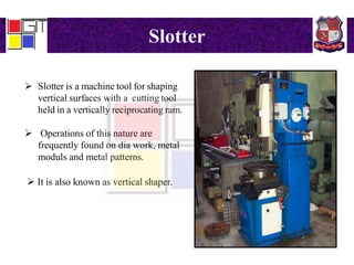
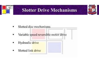
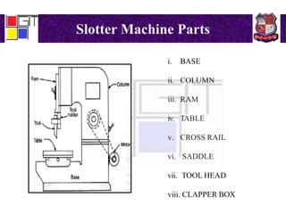
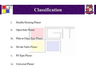
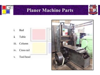
This document provides an overview of planer and slotter machines. It describes that a slotter is a machine tool that uses a vertically reciprocating ram to shape vertical surfaces with a cutting tool. It classifies slotters and describes their drive mechanisms, feed mechanisms, and main parts which include the base, column, ram, table, cross rail, and saddle. It also lists the common operations performed on a slotter like cutting internal grooves. For a planer, it similarly describes the machine, classifies types, and outlines their drive mechanisms, feed mechanisms, main parts, and operations like planing flat surfaces.
Shaping Machine
It is reciprocating type of machine tool used for producing flat surfaces.
Surfaces may be horizontal, vertical or inclined.
Modern shapers can produce contoured surfaces.
It uses reciprocating straight line motion of the tool and a perpendicular feed of the job or the tool.
By moving the work piece across the path of the reciprocating tool, a flat surface is generated regardless of the shape of the tool.
On a shaper, job is fixed on the work table (i.e. job remains stationary) and the tool cuts while reciprocating over the job . The tool is mounted on a reciprocating ram and the table which supports the job is fed normal to the tool motion at each stroke of the ram.
The tool cuts in the forward stroke only except in case of a draw-cut shaper in which the tool cuts in backward stroke of the ram.
The other stroke in both the cases remains idle as there is no cutting action in that stroke.
Base: Shaper base is a heavy structure of cast iron. It supports all the other parts and assemblies (described in the following). It resists vibration and high compressive loads being of cast iron. Base is bolted down to the shop floor through foundation bolts .
etc....
about shaper machine, planer machine, and milling machine.
how to use these machines.
and how to work these machines.
easy to learn about these machines.
A clear view on Shaping , slotting and planning machines kinematic scheme and their principal parts and difference between planning and shaping machine
i hope, it will helpful to the students and peoples in the search of topics mentioned
it is informative to study to even get passing marks or for revision
This report represents the whole topics i had learned during my Industrial training at BITAC. File contains related pictures, description of various shops and related things on machine tools.
MACHINING OPERATIONS AND MACHINE TOOLS
Methods of Holding the Work in a Lathe (Chuck,Collet,face Plate,Holding the Work Between Centers)
Work Holding for Drill Presses
Boring Drilling, Reaming, Tapping Milling
Peripheral Milling vs. Face Milling
Shaper and Planer
Broaching
Unit 3A1 Lathe turning and related operationsMechbytes
Coverage of machine tools classification, types, functions and Lathe machine, Turning & related operations, Lathe construction, parts, accessories and attachments
Saudi Arabia stands as a titan in the global energy landscape, renowned for its abundant oil and gas resources. It's the largest exporter of petroleum and holds some of the world's most significant reserves. Let's delve into the top 10 oil and gas projects shaping Saudi Arabia's energy future in 2024.
Cosmetic shop management system project report.pdfKamal Acharya
Buying new cosmetic products is difficult. It can even be scary for those who have sensitive skin and are prone to skin trouble. The information needed to alleviate this problem is on the back of each product, but it's thought to interpret those ingredient lists unless you have a background in chemistry.
Instead of buying and hoping for the best, we can use data science to help us predict which products may be good fits for us. It includes various function programs to do the above mentioned tasks.
Data file handling has been effectively used in the program.
The automated cosmetic shop management system should deal with the automation of general workflow and administration process of the shop. The main processes of the system focus on customer's request where the system is able to search the most appropriate products and deliver it to the customers. It should help the employees to quickly identify the list of cosmetic product that have reached the minimum quantity and also keep a track of expired date for each cosmetic product. It should help the employees to find the rack number in which the product is placed.It is also Faster and more efficient way.
About
Indigenized remote control interface card suitable for MAFI system CCR equipment. Compatible for IDM8000 CCR. Backplane mounted serial and TCP/Ethernet communication module for CCR remote access. IDM 8000 CCR remote control on serial and TCP protocol.
• Remote control: Parallel or serial interface.
• Compatible with MAFI CCR system.
• Compatible with IDM8000 CCR.
• Compatible with Backplane mount serial communication.
• Compatible with commercial and Defence aviation CCR system.
• Remote control system for accessing CCR and allied system over serial or TCP.
• Indigenized local Support/presence in India.
• Easy in configuration using DIP switches.
Technical Specifications
Indigenized remote control interface card suitable for MAFI system CCR equipment. Compatible for IDM8000 CCR. Backplane mounted serial and TCP/Ethernet communication module for CCR remote access. IDM 8000 CCR remote control on serial and TCP protocol.
Key Features
Indigenized remote control interface card suitable for MAFI system CCR equipment. Compatible for IDM8000 CCR. Backplane mounted serial and TCP/Ethernet communication module for CCR remote access. IDM 8000 CCR remote control on serial and TCP protocol.
• Remote control: Parallel or serial interface
• Compatible with MAFI CCR system
• Copatiable with IDM8000 CCR
• Compatible with Backplane mount serial communication.
• Compatible with commercial and Defence aviation CCR system.
• Remote control system for accessing CCR and allied system over serial or TCP.
• Indigenized local Support/presence in India.
Application
• Remote control: Parallel or serial interface.
• Compatible with MAFI CCR system.
• Compatible with IDM8000 CCR.
• Compatible with Backplane mount serial communication.
• Compatible with commercial and Defence aviation CCR system.
• Remote control system for accessing CCR and allied system over serial or TCP.
• Indigenized local Support/presence in India.
• Easy in configuration using DIP switches.
Hierarchical Digital Twin of a Naval Power SystemKerry Sado
A hierarchical digital twin of a Naval DC power system has been developed and experimentally verified. Similar to other state-of-the-art digital twins, this technology creates a digital replica of the physical system executed in real-time or faster, which can modify hardware controls. However, its advantage stems from distributing computational efforts by utilizing a hierarchical structure composed of lower-level digital twin blocks and a higher-level system digital twin. Each digital twin block is associated with a physical subsystem of the hardware and communicates with a singular system digital twin, which creates a system-level response. By extracting information from each level of the hierarchy, power system controls of the hardware were reconfigured autonomously. This hierarchical digital twin development offers several advantages over other digital twins, particularly in the field of naval power systems. The hierarchical structure allows for greater computational efficiency and scalability while the ability to autonomously reconfigure hardware controls offers increased flexibility and responsiveness. The hierarchical decomposition and models utilized were well aligned with the physical twin, as indicated by the maximum deviations between the developed digital twin hierarchy and the hardware.
Overview of the fundamental roles in Hydropower generation and the components involved in wider Electrical Engineering.
This paper presents the design and construction of hydroelectric dams from the hydrologist’s survey of the valley before construction, all aspects and involved disciplines, fluid dynamics, structural engineering, generation and mains frequency regulation to the very transmission of power through the network in the United Kingdom.
Author: Robbie Edward Sayers
Collaborators and co editors: Charlie Sims and Connor Healey.
(C) 2024 Robbie E. Sayers
CFD Simulation of By-pass Flow in a HRSG module by R&R Consult.pptxR&R Consult
CFD analysis is incredibly effective at solving mysteries and improving the performance of complex systems!
Here's a great example: At a large natural gas-fired power plant, where they use waste heat to generate steam and energy, they were puzzled that their boiler wasn't producing as much steam as expected.
R&R and Tetra Engineering Group Inc. were asked to solve the issue with reduced steam production.
An inspection had shown that a significant amount of hot flue gas was bypassing the boiler tubes, where the heat was supposed to be transferred.
R&R Consult conducted a CFD analysis, which revealed that 6.3% of the flue gas was bypassing the boiler tubes without transferring heat. The analysis also showed that the flue gas was instead being directed along the sides of the boiler and between the modules that were supposed to capture the heat. This was the cause of the reduced performance.
Based on our results, Tetra Engineering installed covering plates to reduce the bypass flow. This improved the boiler's performance and increased electricity production.
It is always satisfying when we can help solve complex challenges like this. Do your systems also need a check-up or optimization? Give us a call!
Work done in cooperation with James Malloy and David Moelling from Tetra Engineering.
More examples of our work https://www.r-r-consult.dk/en/cases-en/
3. Slotter
Slotter is a machine tool for shaping
vertical surfaces with a cutting tool
held in a vertically reciprocating ram.
Operations of this nature are
frequently found on dia work, metal
moduls and metal patterns.
It is also known as vertical shaper.
6. Slotter Feed Mechanism
As mentioned earlier the slotter table is given feed in three directions :
The circular feed is accomplished by a revolving work table equipped
with an indexing mechanism.
The manual feed to the table is provided through bolt and nut drives.
Longitudinal rotary feed gets its motion from a cam groove cut on the
face of the bull gear.
Longitudinal
Cross
Circular
7. Slotter Machine Parts
i. BASE
ii. COLUMN
iii. RAM
iv. TABLE
v. CROSS RAIL
vi. SADDLE
vii. TOOL HEAD
viii. CLAPPER BOX
8. Operations done on a Slotter
The following operations can be performed on the Slotter :
Cutting of internal grooves or key ways
Cutting of internal gears
Cutting of recesses
9. Planer
Planer is a machine with a cutting tool that makes repeated
horizontal strokes across the surface of a workpiece used to cut
flat surfaces into metal.
Planing is much less efficient than other basic
machining processes, such as milling, that will produce such
surfaces.
10. Classification
i. Double Housing Planer
ii. Open Side Planer
iii. Plate or Edge Type Planer
iv. Divide Table Planer
v. Pit Type Planer
vi. Universal Planer
11. Planer Drive Mechanisms
The different mechanisms used to drive the planer table include the
following :
i. Open and crossed belt drive
ii. Reversible motor drive
12. Planer Feed Mechanism
The feed in a planer is provided intermittently between the two strokes.
In the planer both the cross feed and down feed are given to the tools on
the cross rail.
The automatic feed drive for a planer may be provided by two methods :
i. By friction disc
ii. By electric drive
14. Operations done on a Planer
The following operations can be performed on the Planer :
Planing of horizontal flat surface
Planing of vertical flat surfaces
Planing at an angle
Planing curved surfaces
Planing different types of slots, grooves etc.