Downloaded 105 times
![Electronic eye for night device switching
using 555 timer
BY
K.Ranga Uma Maheshwar Rao [107Z1A0205]
S.Yadagiri Reddy [107Z1A0240]
B.Venkanna [107Z1A0205]
T.Pavan Kishore [107Z1A0243]
Under the guidance of :
Mr Rajesh Kumar Samala
Asst.professor , nnresgi](https://image.slidesharecdn.com/readjusted-151227040649/85/ELECTRONIC-EYE-FOR-NIGHT-DEVICE-SWITCHING-USING-555-TIMER-1-320.jpg)
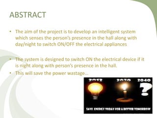
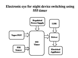
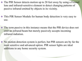
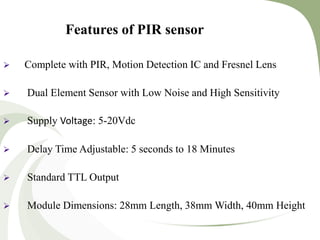
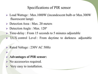
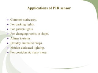

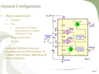
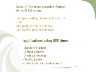
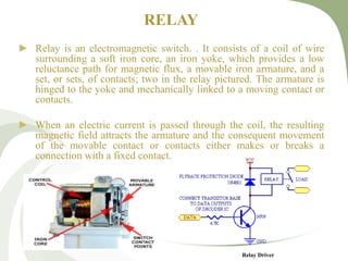
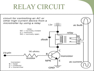
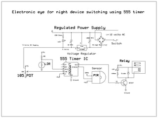
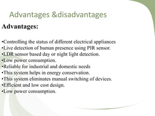
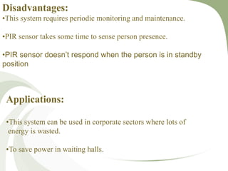


The document describes the development of an intelligent system that utilizes sensors and a 555 timer to control electrical appliances based on human presence and time of day. It outlines the main components, including PIR and LDR sensors, along with the advantages and potential applications of the system for energy conservation. The project successfully integrates various hardware features to enable automatic switching, significantly reducing power waste.