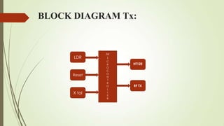
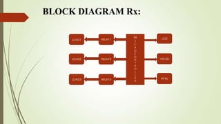
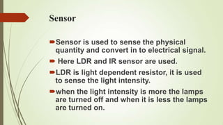
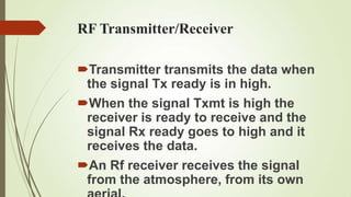
BUILDING LIGHTING AUTOMATION
THROUGH INTEGRATION OF DALI WITH
WIRELESS SENSOR NETWORK
INTRODUCTION

Energy demand is the rising problem
 in today’s world.
So it is necessary to solve the energy
 crisis problem.
It is essential to monitor the energy
 consumption in Buildings.
This project focuses on the integration of
 Digital Addressable Lighting Interface
 (DALI) devices in wireless sensor
 networks – e.g. heating ventilation and air
 conditioning, lighting control, alarms, etc.
Final building automation system has
 different subsystems which are finally
 taken to an integrated building
 management system.
The main purpose of this project is to
 provide a wireless sensor network which
 acquires the data from the sensing
Where the automation control
 technique automatically detect the
 human interference neglecting the
 object or material things, it turns
 on/off the electronic appliances.
And also we apply automation
 lighting technique where depending
 upon the intensity of light the sensor
 controls the objects.
BLOCK DIAGRAM Tx:


              M
      LDR     I
              C
              R   HT12E
              O
              C
              O
      Reset   N
              T
              R
              O   RF TX
              L
      X tal   L
              E
              R
BLOCK DIAGRAM Rx:

                      M   LCD
     LOAD1   RELAY1
                      I
                      C
                      R
                      O
                      C
                      O
     LOAD2   RELAY2   N   HD12D
                      T
                      R
                      O
                      L
                      L
                      E   RF Rx
     LOAD3   RELAY3
                      R
Sensor

Sensor is used to sense the physical
 quantity and convert in to electrical signal.
 Here LDR and IR sensor are used.
LDR is light dependent resistor, it is used
 to sense the light intensity.
when the light intensity is more the lamps
 are turned off and when it is less the lamps
 are turned on.
X-tal Crystal Oscillator

A crystal oscillator is an electronic
 oscillator circuit.
The Oscillator uses the mechanical
 resonance of a vibrating crystal of
 piezoelectric material to create an
 electrical signal with a very precise
 frequency.
Microcontroller

We can use many type of controller like
 PLC, PID microcontroller
 But here we are going to use embedded
 controller.
From the sensor you are getting analog
 signals so we have to convert the analog
 signal in to digital signal by using opt
 coupler.
Encoder/decoder

An encoder is a device, circuit,
 transducer, software program,
 algorithm or person that converts
 information from one format or code
 to another.
A decoder is a device which does the
 reverse operation of an encoder,
 undoing the encoding so that the
RF Transmitter/Receiver

Transmitter transmits the data when
 the signal Tx ready is in high.
When the signal Txmt is high the
 receiver is ready to receive and the
 signal Rx ready goes to high and it
 receives the data.
An Rf receiver receives the signal
 from the atmosphere, from its own
LCD


It displays the output from thee
 microcontroller.
To Verify the Entire Process of
 working Carried out.
Relay

Relay is a electromechanical switch.
 After giving supply nc gets changed
 in to no and no gets changed into nc.
We can use many no of relays
 depending upon the application used
Conclusion


The major advantage of this project is
 to reduce the man power, power
 consumption cost.
It is very useful in urban houses,
 offices, hospitals, Old and Physically
 challenged people.

Building light automation (1)

  • 1.
    BUILDING LIGHTING AUTOMATION THROUGHINTEGRATION OF DALI WITH WIRELESS SENSOR NETWORK
  • 2.
    INTRODUCTION Energy demand isthe rising problem in today’s world. So it is necessary to solve the energy crisis problem. It is essential to monitor the energy consumption in Buildings.
  • 3.
    This project focuseson the integration of Digital Addressable Lighting Interface (DALI) devices in wireless sensor networks – e.g. heating ventilation and air conditioning, lighting control, alarms, etc. Final building automation system has different subsystems which are finally taken to an integrated building management system. The main purpose of this project is to provide a wireless sensor network which acquires the data from the sensing
  • 4.
    Where the automationcontrol technique automatically detect the human interference neglecting the object or material things, it turns on/off the electronic appliances. And also we apply automation lighting technique where depending upon the intensity of light the sensor controls the objects.
  • 5.
    BLOCK DIAGRAM Tx: M LDR I C R HT12E O C O Reset N T R O RF TX L X tal L E R
  • 6.
    BLOCK DIAGRAM Rx: M LCD LOAD1 RELAY1 I C R O C O LOAD2 RELAY2 N HD12D T R O L L E RF Rx LOAD3 RELAY3 R
  • 7.
    Sensor Sensor is usedto sense the physical quantity and convert in to electrical signal.  Here LDR and IR sensor are used. LDR is light dependent resistor, it is used to sense the light intensity. when the light intensity is more the lamps are turned off and when it is less the lamps are turned on.
  • 8.
    X-tal Crystal Oscillator Acrystal oscillator is an electronic oscillator circuit. The Oscillator uses the mechanical resonance of a vibrating crystal of piezoelectric material to create an electrical signal with a very precise frequency.
  • 9.
    Microcontroller We can usemany type of controller like PLC, PID microcontroller  But here we are going to use embedded controller. From the sensor you are getting analog signals so we have to convert the analog signal in to digital signal by using opt coupler.
  • 10.
    Encoder/decoder An encoder isa device, circuit, transducer, software program, algorithm or person that converts information from one format or code to another. A decoder is a device which does the reverse operation of an encoder, undoing the encoding so that the
  • 11.
    RF Transmitter/Receiver Transmitter transmitsthe data when the signal Tx ready is in high. When the signal Txmt is high the receiver is ready to receive and the signal Rx ready goes to high and it receives the data. An Rf receiver receives the signal from the atmosphere, from its own
  • 12.
    LCD It displays theoutput from thee microcontroller. To Verify the Entire Process of working Carried out.
  • 13.
    Relay Relay is aelectromechanical switch.  After giving supply nc gets changed in to no and no gets changed into nc. We can use many no of relays depending upon the application used
  • 14.
    Conclusion The major advantageof this project is to reduce the man power, power consumption cost. It is very useful in urban houses, offices, hospitals, Old and Physically challenged people.