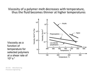
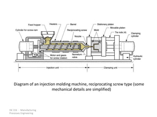
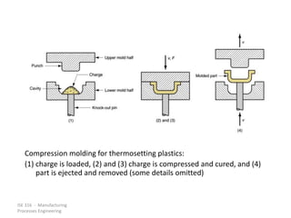
ISE 316 - Manufacturing
Processes Engineering
SHAPING PROCESSES FOR PLASTICS
• Properties of Polymer Melts
• Extrusion and Related Processes
• Molding Processes
• Casting
• Polymer Foam Processing and Forming
• Product Design Considerations
ISE 316 - Manufacturing
Processes Engineering
Plastic Products
• Plastics can be shaped into a wide variety of
products:
– Molded parts
– Extruded sections
– Films
– Sheets
– Insulation coatings on electrical wires
– Fibers for textiles
ISE 316 - Manufacturing
Processes Engineering
Why Plastic Shaping Processes are
Important
• Almost unlimited variety of part geometries
• Plastic molding is a net shape process; further
shaping is not needed
• Less energy is required than for metals
because processing temperatures are much
lower
– Handling of product is simplified during
production because of lower temperatures
• Painting or plating is usually not required
ISE 316 - Manufacturing
Processes Engineering
Two Types of Plastics
1. Thermoplastics
– Chemical structure remains unchanged during
heating and shaping
– More important commercially, comprising more
than 70% of total plastics tonnage
2. Thermosets
– Undergo a curing process during heating and
shaping, causing a permanent change (called
cross-linking) in molecular structure
– Once cured, they cannot be re-melted
ISE 316 - Manufacturing
Processes Engineering
Classification of Plastics Shaping
Processes by Product Geometry
• Extruded products with constant cross-section
• Continuous sheets and films
• Continuous filaments (fibers)
• Molded parts which are mostly solid
• Hollow molded parts with relatively thin walls
• Discrete parts made of formed sheets and films
• Castings
• Foamed products
ISE 316 - Manufacturing
Processes Engineering
Polymer Melts
• To shape a thermoplastic polymer it must be
heated so that it softens to the consistency of
a liquid
• In this form, it is called a polymer melt
• Important properties:
– Viscosity
– Viscoelasticity
ISE 316 - Manufacturing
Processes Engineering
Viscosity of Polymer Melts
Fluid property that relates shear stress to shear rate
during flow
• Due to its high molecular weight, a polymer melt
is a thick fluid with high viscosity
• Important because most polymer shaping
processes involve flow through small channels or
die openings
• Flow rates are often large, leading to high shear
rates and shear stresses, so significant pressures
are required to accomplish the processes
ISE 316 - Manufacturing
Processes Engineering
Viscosity of a polymer melt decreases with temperature,
thus the fluid becomes thinner at higher temperatures
Viscosity as a
function of
temperature for
selected polymers
at a shear rate of
103 s-1
ISE 316 - Manufacturing
Processes Engineering
Viscoelasticity
Combination of viscosity and elasticity
• Possessed by both polymer solids and
polymer melts
• Example: die swell in extrusion, in which the
hot plastic expands when exiting the die
opening
ISE 316 - Manufacturing
Processes Engineering
Die Swell
Extruded material "remembers" its former shape
when in the larger cross-section of the extruder and
attempts to return to it after leaving the die orifice
Die swell, a manifestation of viscoelasticity in polymer melts, as
depicted here on exiting an extrusion die
ISE 316 - Manufacturing
Processes Engineering
Extrusion
Compression process in which material is forced to
flow through a die orifice to provide long
continuous product whose cross-sectional shape
is determined by the shape of the orifice
• Widely used for thermoplastics and elastomers to
mass produce items such as tubing, pipes, hose,
structural shapes, sheet and film, continuous
filaments, and coated electrical wire
• Carried out as a continuous process; extrudate is
then cut into desired lengths
ISE 316 - Manufacturing
Processes Engineering
Components and features of a (single-screw) extruder for plastics and
elastomers
ISE 316 - Manufacturing
Processes Engineering
Two Main Components of an Extruder
1. Barrel
2. Screw
• Die - not an extruder component
– It is a special tool that must be fabricated for
particular profile to be produced
ISE 316 - Manufacturing
Processes Engineering
Extruder Barrel
• Internal diameter typically ranges from 25 to
150 mm (1.0 to 6.0 in.)
• L/D ratios usually between 10 and 30: higher
ratios for thermoplastic, lower ratios for
elastomers
• Feedstock fed by gravity onto screw whose
rotation moves material through barrel
• Electric heaters melt feedstock; subsequent
mixing and mechanical working adds heat
which maintains the melt
ISE 316 - Manufacturing
Processes Engineering
Extruder Screw
• Divided into sections to serve several
functions:
– Feed section - feedstock is moved from hopper
and preheated
– Compression section - polymer is transformed
into fluid, air mixed with pellets is extracted from
melt, and material is compressed
– Metering section - melt is homogenized and
sufficient pressure developed to pump it through
die opening
ISE 316 - Manufacturing
Processes Engineering
Die Configurations and Extruded
Products
• The shape of the die orifice determines the
cross-sectional shape of the extrudate
• Common die profiles and corresponding
extruded shapes:
– Solid profiles
– Hollow profiles, such as tubes
– Wire and cable coating
– Sheet and film
– Filaments
ISE 316 - Manufacturing
Processes Engineering
Extrusion of Solid Profiles
• Regular shapes such as
– Rounds
– Squares
• Irregular cross-sections such as
– Structural shapes
– Door and window moldings
– Automobile trim
– House siding
ISE 316 - Manufacturing
Processes Engineering
(a) Side view cross-section of an extrusion die for solid regular shapes,
such as round stock; (b) front view of die, with profile of extrudate Die
swell is evident in both views
(Some die construction details are simplified or omitted for clarity.)
ISE 316 - Manufacturing
Processes Engineering
Hollow Profiles
• Examples: tubes, pipes, hoses, and other
cross-sections containing holes
• Hollow profiles require mandrel to form the
shape
• Mandrel held in place using a spider
– Polymer melt flows around legs supporting the
mandrel to reunite into a monolithic tube wall
• Mandrel often includes an air channel through
which air is blown to maintain hollow form of
extrudate during hardening
ISE 316 - Manufacturing
Processes Engineering
Side view cross-section of extrusion die for shaping hollow cross-sections
such as tubes and pipes; Section A-A is a front view cross-section
showing how the mandrel is held in place; Section B-B shows the
tubular cross-section just prior to exiting the die; die swell causes an
enlargement of the diameter
ISE 316 - Manufacturing
Processes Engineering
Wire and Cable Coating
• Polymer melt is applied to bare wire as it is
pulled at high speed through a die
– A slight vacuum is drawn between wire and
polymer to promote adhesion of coating
• Wire provides rigidity during cooling -
usually aided by passing coated wire
through a water trough
• Product is wound onto large spools at
speeds up to 50 m/s (10,000 ft/min)
ISE 316 - Manufacturing
Processes Engineering
Side view cross-section of die for coating of electrical wire by extrusion
ISE 316 - Manufacturing
Processes Engineering
Polymer Sheet and Film
• Sheet
– Thickness from 0.5 mm (0.020 in.) to about 12.5
mm (0.5 in.)
– Used for products such as flat window glazing and
stock for thermoforming
• Film
– Thickness below 0.5 mm (0.020 in.)
– Used for packaging (product wrapping material,
grocery bags, and garbage bags)
– Thicker film applications include pool covers and
liners for irrigation ditches
ISE 316 - Manufacturing
Processes Engineering
Materials for Polymer Sheet and Film
• All thermoplastic polymers
– Polyethylene, mostly low density PE
– Polypropylene
– Polyvinylchloride
– Cellophane
ISE 316 - Manufacturing
Processes Engineering
Sheet and Film Production Processes
• Most widely used processes are continuous,
high production operations
• Processes include:
– Slit-Die Extrusion of Sheet and Film
– Blown-Film Extrusion Process
– Calendering
ISE 316 - Manufacturing
Processes Engineering
Slit-Die Extrusion of Sheet and Film
Production of sheet and film by conventional
extrusion, using a narrow slit as the die opening
• Slit may be up to 3 m (10 ft) wide and as narrow
as around 0.4 mm (0.015 in)
• A problem in this method is uniformity of
thickness throughout width of stock, due to
drastic shape change of polymer melt during its
flow through die
• Edges of film usually must be trimmed because of
thickening at edges
ISE 316 - Manufacturing
Processes Engineering
One of several die configurations for extruding sheet and film
ISE 316 - Manufacturing
Processes Engineering
Blown-Film Extrusion Process
Combines extrusion and blowing to produce a
tube of thin film
• Process begins with extrusion of tube that is
drawn upward while still molten and
simultaneously expanded by air inflated into it
through die mandrel
• Air is blown into tube to maintain uniform film
thickness and tube diameter
ISE 316 - Manufacturing
Processes Engineering
Blown-film process
for high
production of thin
tubular film
ISE 316 - Manufacturing
Processes Engineering
Calendering
Feedstock is passed through a series of rolls to
reduce thickness to desired gage
• Equipment is expensive, but production rate is
high
• Process is noted for good surface finish and high
gage accuracy
• Typical materials: rubber or rubbery
thermoplastics such as plasticized PVC
• Products: PVC floor covering, shower curtains,
vinyl table cloths, pool liners, and inflatable boats
and toys
ISE 316 - Manufacturing
Processes Engineering
A typical roll configuration in calendering
ISE 316 - Manufacturing
Processes Engineering
Fiber and Filament Products
• Most important application of fibers and
filaments is in textiles
• Their use as reinforcing materials in plastics
(composites) is growing, but still small
compared to textiles
• Definitions:
– Fiber - a long, thin strand whose length is at least
100 times its cross-section
– Filament - a fiber of continuous length
ISE 316 - Manufacturing
Processes Engineering
Materials for Fibers and Filaments
• Fibers can be natural or synthetic
• Synthetic fibers constitute about 75% of total
fiber market today:
– Polyester is the most important
– Others: nylon, acrylics, and rayon
• Natural fibers are about 25% of total:
– Cotton is by far the most important staple
– Wool production is significantly less than cotton
ISE 316 - Manufacturing
Processes Engineering
Fiber and Filament Production -
Spinning
• The term spinning is a holdover from methods used to
draw and twist natural fibers into yarn or thread
For synthetic fibers, spinning = extruding a polymer melt
or solution through a spinneret (a die with multiple
small holes), then drawing and winding the product
onto a bobbin
• Three variations, depending on polymer processed:
1. Melt spinning
2. Dry spinning
3. Wet spinning
ISE 316 - Manufacturing
Processes Engineering
Melt Spinning
Starting polymer is heated to molten state and pumped
through spinneret, similar to conventional extrusion
• Typical spinneret is 6 mm (0.25 in) thick and contains
approximately 50 holes of diameter 0.25 mm (0.010
in)
• Filaments are drawn and air cooled before being
spooled onto bobbin
• Significant extension and thinning of filaments occur
while polymer is still molten, so final diameter
wound onto bobbin may be only 1/10 of extruded
size
• Used to produce filaments of polyesters and nylons
ISE 316 - Manufacturing
Processes Engineering
Melt spinning of
continuous
filaments
ISE 316 - Manufacturing
Processes Engineering
Dry Spinning
Similar to melt spinning, but starting polymer is
in solution and solvent can be separated by
evaporation
• First step is extrusion through spinneret
• Extrudate is pulled through a heated chamber
which removes the solvent, leaving the
polymer
• Used to produce filaments of cellulose
acetates and acrylics
ISE 316 - Manufacturing
Processes Engineering
Wet Spinning
• Polymer is also in solution, only solvent is
non-volatile
• To separate polymer, extrudate is passed
through a liquid chemical that coagulates or
precipitates the polymer into coherent strands
which are then collected onto bobbins
• Used to produce filaments of rayon
(regenerated cellulose)
ISE 316 - Manufacturing
Processes Engineering
Subsequent Processing of Filaments
• Filaments produced by any of the three
processes are usually subjected to further cold
drawing to align crystal structure along
direction of filament axis
– Extensions of 2 to 8 are typical
– Effect is to significantly increase tensile strength
– Drawing is accomplished by pulling filament
between two spools, where winding spool is
driven at a faster speed than unwinding spool
ISE 316 - Manufacturing
Processes Engineering
Injection Molding
Polymer is heated to a highly plastic state and
forced to flow under high pressure into a mold
cavity where it solidifies; molded part is then
removed from cavity
• Produces discrete components almost always
to net shape
• Typical cycle time 10 to 30 sec., but cycles of
one minute or more are not uncommon
• Mold may contain multiple cavities, so
multiple moldings are produced each cycle
ISE 316 - Manufacturing
Processes Engineering
Injection Molded Parts (Moldings)
• Complex and intricate shapes are possible
• Shape limitations:
– Capability to fabricate a mold whose cavity is the
same geometry as part
– Shape must allow for part removal from mold
• Part size from  50 g (2 oz) up to  25 kg
(more than 50 lb), e.g., automobile bumpers
• Injection molding is economical only for large
production quantities due to high cost of mold
ISE 316 - Manufacturing
Processes Engineering
Injection Molding Machine
• Two principal components:
– Injection unit – melts and delivers polymer melt,
operates much like an extruder
– Clamping unit – opens and closes mold each
injection cycle
ISE 316 - Manufacturing
Processes Engineering
Diagram of an injection molding machine, reciprocating screw type (some
mechanical details are simplified)
ISE 316 - Manufacturing
Processes Engineering
Injection Unit of Molding Machine
• Consists of barrel fed from one end by a
hopper containing supply of plastic pellets
• Inside the barrel is a screw which has two
functions:
1. Rotates for mixing and heating the polymer
2. Acts as a ram to inject molten plastic into mold
• Non-return valve near tip of screw prevents melt
flowing backward along screw threads
• Later in molding cycle ram retracts to its former
position
ISE 316 - Manufacturing
Processes Engineering
Clamping Unit of Molding Machine
• Functions:
1. Holds two halves of mold in proper alignment
with each other
2. Keeps mold closed during injection by applying a
clamping force sufficient to resist injection force
3. Opens and closes the mold at the appropriate
times in molding cycle
ISE 316 - Manufacturing
Processes Engineering
Typical molding cycle:
(1) mold is closed
ISE 316 - Manufacturing
Processes Engineering
Typical molding cycle:
(2) melt is injected into cavity
ISE 316 - Manufacturing
Processes Engineering
Typical molding cycle:
(3) screw is retracted
ISE 316 - Manufacturing
Processes Engineering
Typical molding cycle:
(4) mold opens and part is ejected
ISE 316 - Manufacturing
Processes Engineering
The Mold
• The special tool in injection molding
• Custom designed and fabricated for the part
to be produced
• When production run is finished, the mold is
replaced with a new mold for the next part
• Various types of mold for injection molding:
– Two-plate mold
– Three-plate mold
– Hot-runner mold
ISE 316 - Manufacturing
Processes Engineering
Details of a two-plate mold for thermoplastic injection molding: (a) closed.
Mold has two cavities to produce two cup-shaped parts with each
injection shot
ISE 316 - Manufacturing
Processes Engineering
Details of a two-plate mold for thermoplastic injection molding: (b)
open
ISE 316 - Manufacturing
Processes Engineering
Injection Molding Machines
• Injection molding machines differ in both
injection unit and clamping unit
• The name of the injection molding machine is
generally based on the type of injection unit
used
– Example: Reciprocating-screw machine
• Several clamping designs
– Examples: mechanical (toggle) vs. hydraulic
ISE 316 - Manufacturing
Processes Engineering
Shrinkage
Reduction in linear size during cooling from
molding to room temperature
• Polymers have high thermal expansion
coefficients, so significant shrinkage occurs
during cooling in mold
• Typical shrinkage values for selected polymers:
Plastic Shrinkage, mm/mm (in/in)
Nylon-6,6 0.020
Polyethylene 0.025
Polystyrene 0.004
PVC 0.005
ISE 316 - Manufacturing
Processes Engineering
Compensation for Shrinkage
• Dimensions of mold cavity must be larger than
specified part dimensions:
Dc = Dp + DpS + DpS2
where Dc = dimension of cavity; Dp = molded part
dimension, and S = shrinkage value
• Third term on right hand side corrects for
shrinkage in the shrinkage
ISE 316 - Manufacturing
Processes Engineering
Shrinkage Factors
• Fillers in the plastic tend to reduce shrinkage
• Injection pressure – as pressure is increased,
forcing more material into mold cavity, shrinkage
is reduced
• Compaction time - similar effect - forces more
material into cavity during shrinkage
• Molding temperature - higher temperatures
lower polymer melt viscosity, allowing more
material to be packed into mold and reducing
shrinkage
ISE 316 - Manufacturing
Processes Engineering
Thermoplastic Foam Injection Molding
Molding of thermoplastic parts that possess dense
outer skin surrounding lightweight foam center
• Part has high stiffness - to - weight ratio suited to
structural applications
• Produced either by introducing a gas into molten
plastic in injection unit or by mixing a
gas - producing ingredient with starting pellets
• During injection, a small amount of melt is forced
into mold cavity, where it expands to fill cavity
• Foam in contact with cold mold surface collapses to
form dense skin, while core retains cellular
structure
ISE 316 - Manufacturing
Processes Engineering
Injection Molding of Thermosets
• Equipment and operating procedure must be
modified to avoid premature cross-linking of TS
polymer
– Reciprocating-screw injection unit with shorter barrel
length
• Temperatures in barrel are relatively low
• Melt is injected into a heated mold, where
cross-linking occurs to harden plastic
• Mold is then opened and part is removed
• Curing is the most time-consuming step in the
cycle
ISE 316 - Manufacturing
Processes Engineering
Reaction Injection Molding
Two highly reactive liquid ingredients are mixed and
immediately injected into a mold cavity where
chemical reactions leading to solidification occur
• RIM was developed with polyurethane to
produce large automotive parts such as bumpers
and fenders
– RIM polyurethane parts possess a foam internal
structure surrounded by a dense outer skin
• Other materials used in RIM: epoxies, and
urea-formaldehyde
ISE 316 - Manufacturing
Processes Engineering
Compression Molding
• An old and widely used molding process for
thermosetting plastics
• Applications also include rubber tires and
polymer matrix composite parts
• Molding compound available in several forms:
powders or pellets, liquid, or preform
• Amount of charge must be precisely
controlled to obtain repeatable consistency in
the molded product
ISE 316 - Manufacturing
Processes Engineering
Compression molding for thermosetting plastics:
(1) charge is loaded, (2) and (3) charge is compressed and cured, and (4)
part is ejected and removed (some details omitted)
ISE 316 - Manufacturing
Processes Engineering
Compression Molding Presses
• Oriented vertically
• Contain two platens to which mold halves are
fastened
• Presses have either of two types of actuation:
1. Upstroke of bottom platen
2. Downstroke of top platen
ISE 316 - Manufacturing
Processes Engineering
Molds for Compression Molding
• Simpler than injection molds
• No sprue and runner system in a compression
mold
• Process itself generally limited to simpler part
geometries due to lower flow capabilities of
TS materials
• Mold must be heated, usually by electric
resistance, steam, or hot oil circulation
ISE 316 - Manufacturing
Processes Engineering
Materials and Products in
Compression Molding
• Materials: phenolics, melamine,
urea-formaldehyde, epoxies, urethanes, and
elastomers
• Typical TS moldings: electric plugs, sockets,
and housings; pot handles, and dinnerware
plates
ISE 316 - Manufacturing
Processes Engineering
Transfer Molding
TS charge is loaded into a chamber immediately
ahead of mold cavity, where it is heated;
pressure is then applied to force soft polymer
to flow into heated mold where it cures
• Two variants:
– Pot transfer molding - charge is injected from a
"pot" through a vertical sprue channel into cavity
– Plunger transfer molding – plunger injects charge
from a heated well through channels into cavity
ISE 316 - Manufacturing
Processes Engineering
(a) Pot transfer molding
(1) charge is loaded into pot,
(2) softened polymer is pressed into mold cavity and cured, and
(3) part is ejected
ISE 316 - Manufacturing
Processes Engineering
(b) plunger transfer molding
(1) charge is loaded into pot,
(2) softened polymer is pressed into mold cavity and cured, and
(3) part is ejected
ISE 316 - Manufacturing
Processes Engineering
Compression and Transfer Molding
Compared
• In both processes, scrap is produced each cycle as
leftover material, called the cull
• The TS scrap cannot be recovered
• Transfer molding is capable of molding more
intricate part shapes than compression molding
but not as intricate as injection molding
• Transfer molding lends itself to molding with
inserts, in which a metal or ceramic insert is
placed into cavity prior to injection, and the
plastic bonds to insert during molding
ISE 316 - Manufacturing
Processes Engineering
Blow Molding
Molding process in which air pressure is used to
inflate soft plastic into a mold cavity
• Important for making one-piece hollow plastic
parts with thin walls, such as bottles
• Since these items are used for consumer
beverages in mass markets, production is
typically organized for very high quantities
ISE 316 - Manufacturing
Processes Engineering
Blow Molding Process
• Accomplished in two steps:
1. Fabrication of a starting tube, called a parison
2. Inflation of the tube to desired final shape
• Forming the parison is accomplished by
either
– Extrusion or
– Injection molding
ISE 316 - Manufacturing
Processes Engineering
Extrusion blow molding: (1) extrusion of parison; (2) parison is pinched
at the top and sealed at the bottom around a metal blow pin as the
two halves of the mold come together; (3) the tube is inflated so that
it takes the shape of the mold cavity; and (4) mold is opened to
remove the solidified part
ISE 316 - Manufacturing
Processes Engineering
Injection blow molding: (1) parison is injected molded around a blowing
rod; (2) injection mold is opened and parison is transferred to a blow
mold; (3) soft polymer is inflated to conform to the blow mold; and
(4) blow mold is opened and blown product is removed
ISE 316 - Manufacturing
Processes Engineering
Stretch Blow Molding
Variation of injection blow molding in which blowing rod
extends downward into parison in step 2, stretching
the soft plastic for a more favorable stressing of
polymer than conventional blow molding
• Resulting structure is more rigid, with higher
transparency and better impact resistance
• Most widely used material is polyethylene
terephthalate (PET) which has very low permeability
and is strengthened by stretch blow molding
• Combination of properties makes it ideal as container
for carbonated beverages
ISE 316 - Manufacturing
Processes Engineering
Stretch blow molding:
(1) injection molding of parison; (2) stretching; and (3) blowing
ISE 316 - Manufacturing
Processes Engineering
Materials and Products in Blow
Molding
• Blow molding is limited to thermoplastics
• Materials: high density polyethylene,
polypropylene (PP), polyvinylchloride (PVC),
and polyethylene terephthalate
• Products: disposable containers for liquid
consumer goods, large shipping drums (55
gallon) for liquids and powders, large storage
tanks (2000 gallon), gasoline tanks, toys, and
hulls for sail boards and small boats
ISE 316 - Manufacturing
Processes Engineering
Thermoforming
Flat thermoplastic sheet or film is heated and
deformed into desired shape using a mold
• Heating usually accomplished by radiant
electric heaters located on one or both sides
of starting plastic sheet or film
• Widely used in packaging of products and to
fabricate large items such as bathtubs,
contoured skylights, and internal door liners
for refrigerators
ISE 316 - Manufacturing
Processes Engineering
Vacuum thermoforming:
(1) a flat plastic sheet is softened by heating
ISE 316 - Manufacturing
Processes Engineering
Vacuum thermoforming:
(2) the softened sheet is placed over a concave mold cavity
ISE 316 - Manufacturing
Processes Engineering
Vacuum thermoforming:
(3) a vacuum draws the sheet into the cavity
ISE 316 - Manufacturing
Processes Engineering
(4) the plastic
hardens on
contact with the
cold mold
surface, and the
part is removed
and
subsequently
trimmed from
the web
ISE 316 - Manufacturing
Processes Engineering
Negative Molds vs. Positive Molds
Negative mold – concave cavity
Positive mold - convex shape
• Both types are used in thermoforming
• For positive mold, heated sheet is draped over
convex form and negative or positive pressure
forces plastic against mold surface
ISE 316 - Manufacturing
Processes Engineering
Use of a positive mold in vacuum thermoforming:
(1) the heated plastic sheet is positioned above the convex mold
ISE 316 - Manufacturing
Processes Engineering
Use of a positive mold in vacuum thermoforming:
(2) the clamp is lowered into position, draping the sheet over the mold as
a vacuum forces the sheet against the mold surface
ISE 316 - Manufacturing
Processes Engineering
Materials for Thermoforming
• Only thermoplastics can be thermoformed,
since extruded sheets of thermosetting or
elastomeric polymers have already been
cross-linked and cannot be softened by
reheating
• Common TP polymers: polystyrene, cellulose
acetate, cellulose acetate butyrate, ABS, PVC,
acrylic (polymethylmethacrylate),
polyethylene, and polypropylene
ISE 316 - Manufacturing
Processes Engineering
Applications of Thermoforming
• Thin films: blister packs and skin packs for
packaging commodity products such as
cosmetics, toiletries, small tools, and fasteners
(nails, screws, etc.)
– For best efficiency, filling process to containerize
item(s) is placed immediately downstream from
thermoforming
• Thicker sheet stock: boat hulls, shower stalls,
advertising displays and signs, bathtubs, certain
toys, contoured skylights, internal door liners for
refrigerators
ISE 316 - Manufacturing
Processes Engineering
Casting
Pouring liquid resin into a mold, using gravity to
fill cavity, where polymer hardens
• Both thermoplastics and thermosets are cast
– Thermoplastics: acrylics, polystyrene, polyamides
(nylons) and PVC
– Thermosetting polymers: polyurethane,
unsaturated polyesters, phenolics, and epoxies
• Simpler mold
• Suited to low quantities
ISE 316 - Manufacturing
Processes Engineering
Polymer Foam
A polymer-and-gas mixture that gives the
material a porous or cellular structure
• Most common polymer foams: polystyrene
(Styrofoam, a trademark), polyurethane
• Other polymers: natural rubber ("foamed
rubber") and polyvinylchloride (PVC)
ISE 316 - Manufacturing
Processes Engineering
Characteristic Properties of a Foamed
Polymer
• Low density
• High strength per unit weight
• Good thermal insulation
• Good energy absorbing qualities
ISE 316 - Manufacturing
Processes Engineering
Classification of Polymer Foams
• Elastomeric - matrix polymer is a rubber,
capable of large elastic deformation
• Flexible - matrix is a highly plasticized polymer
such as soft PVC
• Rigid - polymer is a stiff thermoplastic such as
polystyrene or a thermoset such as a phenolic
• Depending on chemical formulation and
degree of cross-linking, polyurethanes can
range over all three categories
ISE 316 - Manufacturing
Processes Engineering
Applications of Polymer Foams
• Characteristic properties of polymer foams, and
the ability to control elastic behavior by selection
of base polymer, make these materials suitable
for certain applications
• Applications: hot beverage cups, heat insulating
structural materials, cores for structural panels,
packaging materials, cushion materials for
furniture and bedding, padding for automobile
dashboards, and products requiring buoyancy
ISE 316 - Manufacturing
Processes Engineering
Two polymer foam structures:
(a) closed cell and (b) open cell
ISE 316 - Manufacturing
Processes Engineering
Extrusion of Polystyrene Foams
• Polystyrene is a thermoplastic polymer
• A physical or chemical blowing agent is fed
into polymer melt near die end of extruder
barrel; thus, extrudate consists of expanded
polymer
• Products: large sheets and boards that are
subsequently cut to size for heat insulation
panels and sections
ISE 316 - Manufacturing
Processes Engineering
Molding Processes for
Polystyrene Foams
• Expandable foam molding - molding material
usually consists of prefoamed polystyrene
beads
• Prefoamed beads are fed into mold cavity
where they are further expanded and fused
together to form molded product
• Products: hot beverage cups of polystyrene
foam are produced in this way
ISE 316 - Manufacturing
Processes Engineering
Shaping Processes for
Polyurethane Foams
• Polyurethane can be thermosetting, elastomer
or thermoplastic (less common)
• Polyurethane foam products are made in a
one-step process in which the two liquid
ingredients are mixed and immediately fed
into a mold or other form
– Polymer is synthesized and part geometry is
created at the same time
• Shaping processes for polyurethane foam:
– Spraying
– Pouring
ISE 316 - Manufacturing
Processes Engineering
Product Design Guidelines for Plastics
– General - I
• Strength and stiffness
– Plastics are not as strong or stiff as metals
– Avoid applications where high stresses will be
encountered
– Creep resistance is also a limitation
– Strength-to-weight ratios for some plastics are
competitive with metals in certain applications
ISE 316 - Manufacturing
Processes Engineering
Product Design Guidelines for Plastics
– General - II
• Impact Resistance
– Capacity of plastics to absorb impact is generally
good; plastics compare favorably with most metals
• Service temperatures
– Plastics are limited relative to engineering metals
and ceramics
• Thermal expansion
– Dimensional changes due to temperature changes
much more significant than for metals
ISE 316 - Manufacturing
Processes Engineering
Product Design Guidelines for Plastics
– General - III
• Many plastics are subject to degradation from
sunlight and other forms of radiation
• Some plastics degrade in oxygen and ozone
atmospheres
• Plastics are soluble in many common solvents
• Plastics are resistant to conventional corrosion
mechanisms that afflict many metals
ISE 316 - Manufacturing
Processes Engineering
Product Design Guidelines –
Extruded Plastics - I
• Wall thickness
– Uniform wall thickness is desirable in an extruded
cross-section
– Variations in wall thickness result in nonuniform
plastic flow and uneven cooling which tend to
warp extrudate
ISE 316 - Manufacturing
Processes Engineering
Product Design Guidelines –
Extruded Plastics - II
• Hollow sections
– Hollow sections complicate die design and plastic
flow
– Desirable to use extruded cross-sections that are
not hollow yet satisfy functional requirements
ISE 316 - Manufacturing
Processes Engineering
Product Design Guidelines –
Extruded Plastics III
• Corners
– Sharp corners, inside and outside, should be
avoided in extruded cross-sections, since they
result in uneven flow during processing and stress
concentrations in the final product
ISE 316 - Manufacturing
Processes Engineering
Product Design Guidelines –
Molded Parts - I
• Economic production quantities
– Each part requires a unique mold, and the mold
for any molding process can be costly, particularly
for injection molding
– Minimum production quantities for injection
molding are usually around 10,000 pieces
– For compression molding, minimum quantities are
1000 parts, due to simpler mold designs
– Transfer molding lies between other two
ISE 316 - Manufacturing
Processes Engineering
Product Design Guidelines –
Molded Parts - II
• Part complexity
– Although more complex part geometries mean
more costly molds, it may nevertheless be
economical to design a complex molding if the
alternative involves many individual components
that must be assembled
– An advantage of plastic molding is that it allows
multiple functional features to be combined into
one part
ISE 316 - Manufacturing
Processes Engineering
Product Design Guidelines –
Molded Parts - III
• Wall thickness
– Thick cross-sections are wasteful of material, more
likely to cause warping due to shrinkage, and take
longer to harden
• Reinforcing ribs
– Achieves increased stiffness without excessive
wall thickness
– Ribs should be made thinner than the walls they
reinforce to minimize sink marks on outside wall
ISE 316 - Manufacturing
Processes Engineering
Product Design Guidelines –
Molded Parts - IV
• Corner radii and fillets
– Sharp corners, both external and internal, are
undesirable in molded parts; they interrupt
smooth flow of the melt, tend to create surface
defects, and cause stress concentrations in the
part
• Holes
– Holes are quite feasible in plastic moldings, but
they complicate mold design and part removal
ISE 316 - Manufacturing
Processes Engineering
Product Design Guidelines –
Molded Parts - V
• Draft
– A molded part should be designed with a draft on
its sides to facilitate removal from mold
– Especially important on inside wall of a
cup-shaped part because plastic contracts against
positive mold shape
– Recommended draft:
• For thermosets, around 1/2 to 1
• For thermoplastics, between 1/8 and 1/2
ISE 316 - Manufacturing
Processes Engineering
Product Design Guidelines –
Molded Parts - VI
• Tolerances
– Although shrinkage is predictable under closely
controlled conditions, generous tolerances are
desirable for injection moldings because of
• Variations in process parameters that affect shrinkage
• Diversity of part geometries encountered

Plastic Molding presentation by Rashail-1.pptx

  • 1.
    ISE 316 -Manufacturing Processes Engineering SHAPING PROCESSES FOR PLASTICS • Properties of Polymer Melts • Extrusion and Related Processes • Molding Processes • Casting • Polymer Foam Processing and Forming • Product Design Considerations
  • 2.
    ISE 316 -Manufacturing Processes Engineering Plastic Products • Plastics can be shaped into a wide variety of products: – Molded parts – Extruded sections – Films – Sheets – Insulation coatings on electrical wires – Fibers for textiles
  • 3.
    ISE 316 -Manufacturing Processes Engineering Why Plastic Shaping Processes are Important • Almost unlimited variety of part geometries • Plastic molding is a net shape process; further shaping is not needed • Less energy is required than for metals because processing temperatures are much lower – Handling of product is simplified during production because of lower temperatures • Painting or plating is usually not required
  • 4.
    ISE 316 -Manufacturing Processes Engineering Two Types of Plastics 1. Thermoplastics – Chemical structure remains unchanged during heating and shaping – More important commercially, comprising more than 70% of total plastics tonnage 2. Thermosets – Undergo a curing process during heating and shaping, causing a permanent change (called cross-linking) in molecular structure – Once cured, they cannot be re-melted
  • 5.
    ISE 316 -Manufacturing Processes Engineering Classification of Plastics Shaping Processes by Product Geometry • Extruded products with constant cross-section • Continuous sheets and films • Continuous filaments (fibers) • Molded parts which are mostly solid • Hollow molded parts with relatively thin walls • Discrete parts made of formed sheets and films • Castings • Foamed products
  • 6.
    ISE 316 -Manufacturing Processes Engineering Polymer Melts • To shape a thermoplastic polymer it must be heated so that it softens to the consistency of a liquid • In this form, it is called a polymer melt • Important properties: – Viscosity – Viscoelasticity
  • 7.
    ISE 316 -Manufacturing Processes Engineering Viscosity of Polymer Melts Fluid property that relates shear stress to shear rate during flow • Due to its high molecular weight, a polymer melt is a thick fluid with high viscosity • Important because most polymer shaping processes involve flow through small channels or die openings • Flow rates are often large, leading to high shear rates and shear stresses, so significant pressures are required to accomplish the processes
  • 8.
    ISE 316 -Manufacturing Processes Engineering Viscosity of a polymer melt decreases with temperature, thus the fluid becomes thinner at higher temperatures Viscosity as a function of temperature for selected polymers at a shear rate of 103 s-1
  • 9.
    ISE 316 -Manufacturing Processes Engineering Viscoelasticity Combination of viscosity and elasticity • Possessed by both polymer solids and polymer melts • Example: die swell in extrusion, in which the hot plastic expands when exiting the die opening
  • 10.
    ISE 316 -Manufacturing Processes Engineering Die Swell Extruded material "remembers" its former shape when in the larger cross-section of the extruder and attempts to return to it after leaving the die orifice Die swell, a manifestation of viscoelasticity in polymer melts, as depicted here on exiting an extrusion die
  • 11.
    ISE 316 -Manufacturing Processes Engineering Extrusion Compression process in which material is forced to flow through a die orifice to provide long continuous product whose cross-sectional shape is determined by the shape of the orifice • Widely used for thermoplastics and elastomers to mass produce items such as tubing, pipes, hose, structural shapes, sheet and film, continuous filaments, and coated electrical wire • Carried out as a continuous process; extrudate is then cut into desired lengths
  • 12.
    ISE 316 -Manufacturing Processes Engineering Components and features of a (single-screw) extruder for plastics and elastomers
  • 13.
    ISE 316 -Manufacturing Processes Engineering Two Main Components of an Extruder 1. Barrel 2. Screw • Die - not an extruder component – It is a special tool that must be fabricated for particular profile to be produced
  • 14.
    ISE 316 -Manufacturing Processes Engineering Extruder Barrel • Internal diameter typically ranges from 25 to 150 mm (1.0 to 6.0 in.) • L/D ratios usually between 10 and 30: higher ratios for thermoplastic, lower ratios for elastomers • Feedstock fed by gravity onto screw whose rotation moves material through barrel • Electric heaters melt feedstock; subsequent mixing and mechanical working adds heat which maintains the melt
  • 15.
    ISE 316 -Manufacturing Processes Engineering Extruder Screw • Divided into sections to serve several functions: – Feed section - feedstock is moved from hopper and preheated – Compression section - polymer is transformed into fluid, air mixed with pellets is extracted from melt, and material is compressed – Metering section - melt is homogenized and sufficient pressure developed to pump it through die opening
  • 16.
    ISE 316 -Manufacturing Processes Engineering Die Configurations and Extruded Products • The shape of the die orifice determines the cross-sectional shape of the extrudate • Common die profiles and corresponding extruded shapes: – Solid profiles – Hollow profiles, such as tubes – Wire and cable coating – Sheet and film – Filaments
  • 17.
    ISE 316 -Manufacturing Processes Engineering Extrusion of Solid Profiles • Regular shapes such as – Rounds – Squares • Irregular cross-sections such as – Structural shapes – Door and window moldings – Automobile trim – House siding
  • 18.
    ISE 316 -Manufacturing Processes Engineering (a) Side view cross-section of an extrusion die for solid regular shapes, such as round stock; (b) front view of die, with profile of extrudate Die swell is evident in both views (Some die construction details are simplified or omitted for clarity.)
  • 19.
    ISE 316 -Manufacturing Processes Engineering Hollow Profiles • Examples: tubes, pipes, hoses, and other cross-sections containing holes • Hollow profiles require mandrel to form the shape • Mandrel held in place using a spider – Polymer melt flows around legs supporting the mandrel to reunite into a monolithic tube wall • Mandrel often includes an air channel through which air is blown to maintain hollow form of extrudate during hardening
  • 20.
    ISE 316 -Manufacturing Processes Engineering Side view cross-section of extrusion die for shaping hollow cross-sections such as tubes and pipes; Section A-A is a front view cross-section showing how the mandrel is held in place; Section B-B shows the tubular cross-section just prior to exiting the die; die swell causes an enlargement of the diameter
  • 21.
    ISE 316 -Manufacturing Processes Engineering Wire and Cable Coating • Polymer melt is applied to bare wire as it is pulled at high speed through a die – A slight vacuum is drawn between wire and polymer to promote adhesion of coating • Wire provides rigidity during cooling - usually aided by passing coated wire through a water trough • Product is wound onto large spools at speeds up to 50 m/s (10,000 ft/min)
  • 22.
    ISE 316 -Manufacturing Processes Engineering Side view cross-section of die for coating of electrical wire by extrusion
  • 23.
    ISE 316 -Manufacturing Processes Engineering Polymer Sheet and Film • Sheet – Thickness from 0.5 mm (0.020 in.) to about 12.5 mm (0.5 in.) – Used for products such as flat window glazing and stock for thermoforming • Film – Thickness below 0.5 mm (0.020 in.) – Used for packaging (product wrapping material, grocery bags, and garbage bags) – Thicker film applications include pool covers and liners for irrigation ditches
  • 24.
    ISE 316 -Manufacturing Processes Engineering Materials for Polymer Sheet and Film • All thermoplastic polymers – Polyethylene, mostly low density PE – Polypropylene – Polyvinylchloride – Cellophane
  • 25.
    ISE 316 -Manufacturing Processes Engineering Sheet and Film Production Processes • Most widely used processes are continuous, high production operations • Processes include: – Slit-Die Extrusion of Sheet and Film – Blown-Film Extrusion Process – Calendering
  • 26.
    ISE 316 -Manufacturing Processes Engineering Slit-Die Extrusion of Sheet and Film Production of sheet and film by conventional extrusion, using a narrow slit as the die opening • Slit may be up to 3 m (10 ft) wide and as narrow as around 0.4 mm (0.015 in) • A problem in this method is uniformity of thickness throughout width of stock, due to drastic shape change of polymer melt during its flow through die • Edges of film usually must be trimmed because of thickening at edges
  • 27.
    ISE 316 -Manufacturing Processes Engineering One of several die configurations for extruding sheet and film
  • 28.
    ISE 316 -Manufacturing Processes Engineering Blown-Film Extrusion Process Combines extrusion and blowing to produce a tube of thin film • Process begins with extrusion of tube that is drawn upward while still molten and simultaneously expanded by air inflated into it through die mandrel • Air is blown into tube to maintain uniform film thickness and tube diameter
  • 29.
    ISE 316 -Manufacturing Processes Engineering Blown-film process for high production of thin tubular film
  • 30.
    ISE 316 -Manufacturing Processes Engineering Calendering Feedstock is passed through a series of rolls to reduce thickness to desired gage • Equipment is expensive, but production rate is high • Process is noted for good surface finish and high gage accuracy • Typical materials: rubber or rubbery thermoplastics such as plasticized PVC • Products: PVC floor covering, shower curtains, vinyl table cloths, pool liners, and inflatable boats and toys
  • 31.
    ISE 316 -Manufacturing Processes Engineering A typical roll configuration in calendering
  • 32.
    ISE 316 -Manufacturing Processes Engineering Fiber and Filament Products • Most important application of fibers and filaments is in textiles • Their use as reinforcing materials in plastics (composites) is growing, but still small compared to textiles • Definitions: – Fiber - a long, thin strand whose length is at least 100 times its cross-section – Filament - a fiber of continuous length
  • 33.
    ISE 316 -Manufacturing Processes Engineering Materials for Fibers and Filaments • Fibers can be natural or synthetic • Synthetic fibers constitute about 75% of total fiber market today: – Polyester is the most important – Others: nylon, acrylics, and rayon • Natural fibers are about 25% of total: – Cotton is by far the most important staple – Wool production is significantly less than cotton
  • 34.
    ISE 316 -Manufacturing Processes Engineering Fiber and Filament Production - Spinning • The term spinning is a holdover from methods used to draw and twist natural fibers into yarn or thread For synthetic fibers, spinning = extruding a polymer melt or solution through a spinneret (a die with multiple small holes), then drawing and winding the product onto a bobbin • Three variations, depending on polymer processed: 1. Melt spinning 2. Dry spinning 3. Wet spinning
  • 35.
    ISE 316 -Manufacturing Processes Engineering Melt Spinning Starting polymer is heated to molten state and pumped through spinneret, similar to conventional extrusion • Typical spinneret is 6 mm (0.25 in) thick and contains approximately 50 holes of diameter 0.25 mm (0.010 in) • Filaments are drawn and air cooled before being spooled onto bobbin • Significant extension and thinning of filaments occur while polymer is still molten, so final diameter wound onto bobbin may be only 1/10 of extruded size • Used to produce filaments of polyesters and nylons
  • 36.
    ISE 316 -Manufacturing Processes Engineering Melt spinning of continuous filaments
  • 37.
    ISE 316 -Manufacturing Processes Engineering Dry Spinning Similar to melt spinning, but starting polymer is in solution and solvent can be separated by evaporation • First step is extrusion through spinneret • Extrudate is pulled through a heated chamber which removes the solvent, leaving the polymer • Used to produce filaments of cellulose acetates and acrylics
  • 38.
    ISE 316 -Manufacturing Processes Engineering Wet Spinning • Polymer is also in solution, only solvent is non-volatile • To separate polymer, extrudate is passed through a liquid chemical that coagulates or precipitates the polymer into coherent strands which are then collected onto bobbins • Used to produce filaments of rayon (regenerated cellulose)
  • 39.
    ISE 316 -Manufacturing Processes Engineering Subsequent Processing of Filaments • Filaments produced by any of the three processes are usually subjected to further cold drawing to align crystal structure along direction of filament axis – Extensions of 2 to 8 are typical – Effect is to significantly increase tensile strength – Drawing is accomplished by pulling filament between two spools, where winding spool is driven at a faster speed than unwinding spool
  • 40.
    ISE 316 -Manufacturing Processes Engineering Injection Molding Polymer is heated to a highly plastic state and forced to flow under high pressure into a mold cavity where it solidifies; molded part is then removed from cavity • Produces discrete components almost always to net shape • Typical cycle time 10 to 30 sec., but cycles of one minute or more are not uncommon • Mold may contain multiple cavities, so multiple moldings are produced each cycle
  • 41.
    ISE 316 -Manufacturing Processes Engineering Injection Molded Parts (Moldings) • Complex and intricate shapes are possible • Shape limitations: – Capability to fabricate a mold whose cavity is the same geometry as part – Shape must allow for part removal from mold • Part size from  50 g (2 oz) up to  25 kg (more than 50 lb), e.g., automobile bumpers • Injection molding is economical only for large production quantities due to high cost of mold
  • 42.
    ISE 316 -Manufacturing Processes Engineering Injection Molding Machine • Two principal components: – Injection unit – melts and delivers polymer melt, operates much like an extruder – Clamping unit – opens and closes mold each injection cycle
  • 43.
    ISE 316 -Manufacturing Processes Engineering Diagram of an injection molding machine, reciprocating screw type (some mechanical details are simplified)
  • 44.
    ISE 316 -Manufacturing Processes Engineering Injection Unit of Molding Machine • Consists of barrel fed from one end by a hopper containing supply of plastic pellets • Inside the barrel is a screw which has two functions: 1. Rotates for mixing and heating the polymer 2. Acts as a ram to inject molten plastic into mold • Non-return valve near tip of screw prevents melt flowing backward along screw threads • Later in molding cycle ram retracts to its former position
  • 45.
    ISE 316 -Manufacturing Processes Engineering Clamping Unit of Molding Machine • Functions: 1. Holds two halves of mold in proper alignment with each other 2. Keeps mold closed during injection by applying a clamping force sufficient to resist injection force 3. Opens and closes the mold at the appropriate times in molding cycle
  • 46.
    ISE 316 -Manufacturing Processes Engineering Typical molding cycle: (1) mold is closed
  • 47.
    ISE 316 -Manufacturing Processes Engineering Typical molding cycle: (2) melt is injected into cavity
  • 48.
    ISE 316 -Manufacturing Processes Engineering Typical molding cycle: (3) screw is retracted
  • 49.
    ISE 316 -Manufacturing Processes Engineering Typical molding cycle: (4) mold opens and part is ejected
  • 50.
    ISE 316 -Manufacturing Processes Engineering The Mold • The special tool in injection molding • Custom designed and fabricated for the part to be produced • When production run is finished, the mold is replaced with a new mold for the next part • Various types of mold for injection molding: – Two-plate mold – Three-plate mold – Hot-runner mold
  • 51.
    ISE 316 -Manufacturing Processes Engineering Details of a two-plate mold for thermoplastic injection molding: (a) closed. Mold has two cavities to produce two cup-shaped parts with each injection shot
  • 52.
    ISE 316 -Manufacturing Processes Engineering Details of a two-plate mold for thermoplastic injection molding: (b) open
  • 53.
    ISE 316 -Manufacturing Processes Engineering Injection Molding Machines • Injection molding machines differ in both injection unit and clamping unit • The name of the injection molding machine is generally based on the type of injection unit used – Example: Reciprocating-screw machine • Several clamping designs – Examples: mechanical (toggle) vs. hydraulic
  • 54.
    ISE 316 -Manufacturing Processes Engineering Shrinkage Reduction in linear size during cooling from molding to room temperature • Polymers have high thermal expansion coefficients, so significant shrinkage occurs during cooling in mold • Typical shrinkage values for selected polymers: Plastic Shrinkage, mm/mm (in/in) Nylon-6,6 0.020 Polyethylene 0.025 Polystyrene 0.004 PVC 0.005
  • 55.
    ISE 316 -Manufacturing Processes Engineering Compensation for Shrinkage • Dimensions of mold cavity must be larger than specified part dimensions: Dc = Dp + DpS + DpS2 where Dc = dimension of cavity; Dp = molded part dimension, and S = shrinkage value • Third term on right hand side corrects for shrinkage in the shrinkage
  • 56.
    ISE 316 -Manufacturing Processes Engineering Shrinkage Factors • Fillers in the plastic tend to reduce shrinkage • Injection pressure – as pressure is increased, forcing more material into mold cavity, shrinkage is reduced • Compaction time - similar effect - forces more material into cavity during shrinkage • Molding temperature - higher temperatures lower polymer melt viscosity, allowing more material to be packed into mold and reducing shrinkage
  • 57.
    ISE 316 -Manufacturing Processes Engineering Thermoplastic Foam Injection Molding Molding of thermoplastic parts that possess dense outer skin surrounding lightweight foam center • Part has high stiffness - to - weight ratio suited to structural applications • Produced either by introducing a gas into molten plastic in injection unit or by mixing a gas - producing ingredient with starting pellets • During injection, a small amount of melt is forced into mold cavity, where it expands to fill cavity • Foam in contact with cold mold surface collapses to form dense skin, while core retains cellular structure
  • 58.
    ISE 316 -Manufacturing Processes Engineering Injection Molding of Thermosets • Equipment and operating procedure must be modified to avoid premature cross-linking of TS polymer – Reciprocating-screw injection unit with shorter barrel length • Temperatures in barrel are relatively low • Melt is injected into a heated mold, where cross-linking occurs to harden plastic • Mold is then opened and part is removed • Curing is the most time-consuming step in the cycle
  • 59.
    ISE 316 -Manufacturing Processes Engineering Reaction Injection Molding Two highly reactive liquid ingredients are mixed and immediately injected into a mold cavity where chemical reactions leading to solidification occur • RIM was developed with polyurethane to produce large automotive parts such as bumpers and fenders – RIM polyurethane parts possess a foam internal structure surrounded by a dense outer skin • Other materials used in RIM: epoxies, and urea-formaldehyde
  • 60.
    ISE 316 -Manufacturing Processes Engineering Compression Molding • An old and widely used molding process for thermosetting plastics • Applications also include rubber tires and polymer matrix composite parts • Molding compound available in several forms: powders or pellets, liquid, or preform • Amount of charge must be precisely controlled to obtain repeatable consistency in the molded product
  • 61.
    ISE 316 -Manufacturing Processes Engineering Compression molding for thermosetting plastics: (1) charge is loaded, (2) and (3) charge is compressed and cured, and (4) part is ejected and removed (some details omitted)
  • 62.
    ISE 316 -Manufacturing Processes Engineering Compression Molding Presses • Oriented vertically • Contain two platens to which mold halves are fastened • Presses have either of two types of actuation: 1. Upstroke of bottom platen 2. Downstroke of top platen
  • 63.
    ISE 316 -Manufacturing Processes Engineering Molds for Compression Molding • Simpler than injection molds • No sprue and runner system in a compression mold • Process itself generally limited to simpler part geometries due to lower flow capabilities of TS materials • Mold must be heated, usually by electric resistance, steam, or hot oil circulation
  • 64.
    ISE 316 -Manufacturing Processes Engineering Materials and Products in Compression Molding • Materials: phenolics, melamine, urea-formaldehyde, epoxies, urethanes, and elastomers • Typical TS moldings: electric plugs, sockets, and housings; pot handles, and dinnerware plates
  • 65.
    ISE 316 -Manufacturing Processes Engineering Transfer Molding TS charge is loaded into a chamber immediately ahead of mold cavity, where it is heated; pressure is then applied to force soft polymer to flow into heated mold where it cures • Two variants: – Pot transfer molding - charge is injected from a "pot" through a vertical sprue channel into cavity – Plunger transfer molding – plunger injects charge from a heated well through channels into cavity
  • 66.
    ISE 316 -Manufacturing Processes Engineering (a) Pot transfer molding (1) charge is loaded into pot, (2) softened polymer is pressed into mold cavity and cured, and (3) part is ejected
  • 67.
    ISE 316 -Manufacturing Processes Engineering (b) plunger transfer molding (1) charge is loaded into pot, (2) softened polymer is pressed into mold cavity and cured, and (3) part is ejected
  • 68.
    ISE 316 -Manufacturing Processes Engineering Compression and Transfer Molding Compared • In both processes, scrap is produced each cycle as leftover material, called the cull • The TS scrap cannot be recovered • Transfer molding is capable of molding more intricate part shapes than compression molding but not as intricate as injection molding • Transfer molding lends itself to molding with inserts, in which a metal or ceramic insert is placed into cavity prior to injection, and the plastic bonds to insert during molding
  • 69.
    ISE 316 -Manufacturing Processes Engineering Blow Molding Molding process in which air pressure is used to inflate soft plastic into a mold cavity • Important for making one-piece hollow plastic parts with thin walls, such as bottles • Since these items are used for consumer beverages in mass markets, production is typically organized for very high quantities
  • 70.
    ISE 316 -Manufacturing Processes Engineering Blow Molding Process • Accomplished in two steps: 1. Fabrication of a starting tube, called a parison 2. Inflation of the tube to desired final shape • Forming the parison is accomplished by either – Extrusion or – Injection molding
  • 71.
    ISE 316 -Manufacturing Processes Engineering Extrusion blow molding: (1) extrusion of parison; (2) parison is pinched at the top and sealed at the bottom around a metal blow pin as the two halves of the mold come together; (3) the tube is inflated so that it takes the shape of the mold cavity; and (4) mold is opened to remove the solidified part
  • 72.
    ISE 316 -Manufacturing Processes Engineering Injection blow molding: (1) parison is injected molded around a blowing rod; (2) injection mold is opened and parison is transferred to a blow mold; (3) soft polymer is inflated to conform to the blow mold; and (4) blow mold is opened and blown product is removed
  • 73.
    ISE 316 -Manufacturing Processes Engineering Stretch Blow Molding Variation of injection blow molding in which blowing rod extends downward into parison in step 2, stretching the soft plastic for a more favorable stressing of polymer than conventional blow molding • Resulting structure is more rigid, with higher transparency and better impact resistance • Most widely used material is polyethylene terephthalate (PET) which has very low permeability and is strengthened by stretch blow molding • Combination of properties makes it ideal as container for carbonated beverages
  • 74.
    ISE 316 -Manufacturing Processes Engineering Stretch blow molding: (1) injection molding of parison; (2) stretching; and (3) blowing
  • 75.
    ISE 316 -Manufacturing Processes Engineering Materials and Products in Blow Molding • Blow molding is limited to thermoplastics • Materials: high density polyethylene, polypropylene (PP), polyvinylchloride (PVC), and polyethylene terephthalate • Products: disposable containers for liquid consumer goods, large shipping drums (55 gallon) for liquids and powders, large storage tanks (2000 gallon), gasoline tanks, toys, and hulls for sail boards and small boats
  • 76.
    ISE 316 -Manufacturing Processes Engineering Thermoforming Flat thermoplastic sheet or film is heated and deformed into desired shape using a mold • Heating usually accomplished by radiant electric heaters located on one or both sides of starting plastic sheet or film • Widely used in packaging of products and to fabricate large items such as bathtubs, contoured skylights, and internal door liners for refrigerators
  • 77.
    ISE 316 -Manufacturing Processes Engineering Vacuum thermoforming: (1) a flat plastic sheet is softened by heating
  • 78.
    ISE 316 -Manufacturing Processes Engineering Vacuum thermoforming: (2) the softened sheet is placed over a concave mold cavity
  • 79.
    ISE 316 -Manufacturing Processes Engineering Vacuum thermoforming: (3) a vacuum draws the sheet into the cavity
  • 80.
    ISE 316 -Manufacturing Processes Engineering (4) the plastic hardens on contact with the cold mold surface, and the part is removed and subsequently trimmed from the web
  • 81.
    ISE 316 -Manufacturing Processes Engineering Negative Molds vs. Positive Molds Negative mold – concave cavity Positive mold - convex shape • Both types are used in thermoforming • For positive mold, heated sheet is draped over convex form and negative or positive pressure forces plastic against mold surface
  • 82.
    ISE 316 -Manufacturing Processes Engineering Use of a positive mold in vacuum thermoforming: (1) the heated plastic sheet is positioned above the convex mold
  • 83.
    ISE 316 -Manufacturing Processes Engineering Use of a positive mold in vacuum thermoforming: (2) the clamp is lowered into position, draping the sheet over the mold as a vacuum forces the sheet against the mold surface
  • 84.
    ISE 316 -Manufacturing Processes Engineering Materials for Thermoforming • Only thermoplastics can be thermoformed, since extruded sheets of thermosetting or elastomeric polymers have already been cross-linked and cannot be softened by reheating • Common TP polymers: polystyrene, cellulose acetate, cellulose acetate butyrate, ABS, PVC, acrylic (polymethylmethacrylate), polyethylene, and polypropylene
  • 85.
    ISE 316 -Manufacturing Processes Engineering Applications of Thermoforming • Thin films: blister packs and skin packs for packaging commodity products such as cosmetics, toiletries, small tools, and fasteners (nails, screws, etc.) – For best efficiency, filling process to containerize item(s) is placed immediately downstream from thermoforming • Thicker sheet stock: boat hulls, shower stalls, advertising displays and signs, bathtubs, certain toys, contoured skylights, internal door liners for refrigerators
  • 86.
    ISE 316 -Manufacturing Processes Engineering Casting Pouring liquid resin into a mold, using gravity to fill cavity, where polymer hardens • Both thermoplastics and thermosets are cast – Thermoplastics: acrylics, polystyrene, polyamides (nylons) and PVC – Thermosetting polymers: polyurethane, unsaturated polyesters, phenolics, and epoxies • Simpler mold • Suited to low quantities
  • 87.
    ISE 316 -Manufacturing Processes Engineering Polymer Foam A polymer-and-gas mixture that gives the material a porous or cellular structure • Most common polymer foams: polystyrene (Styrofoam, a trademark), polyurethane • Other polymers: natural rubber ("foamed rubber") and polyvinylchloride (PVC)
  • 88.
    ISE 316 -Manufacturing Processes Engineering Characteristic Properties of a Foamed Polymer • Low density • High strength per unit weight • Good thermal insulation • Good energy absorbing qualities
  • 89.
    ISE 316 -Manufacturing Processes Engineering Classification of Polymer Foams • Elastomeric - matrix polymer is a rubber, capable of large elastic deformation • Flexible - matrix is a highly plasticized polymer such as soft PVC • Rigid - polymer is a stiff thermoplastic such as polystyrene or a thermoset such as a phenolic • Depending on chemical formulation and degree of cross-linking, polyurethanes can range over all three categories
  • 90.
    ISE 316 -Manufacturing Processes Engineering Applications of Polymer Foams • Characteristic properties of polymer foams, and the ability to control elastic behavior by selection of base polymer, make these materials suitable for certain applications • Applications: hot beverage cups, heat insulating structural materials, cores for structural panels, packaging materials, cushion materials for furniture and bedding, padding for automobile dashboards, and products requiring buoyancy
  • 91.
    ISE 316 -Manufacturing Processes Engineering Two polymer foam structures: (a) closed cell and (b) open cell
  • 92.
    ISE 316 -Manufacturing Processes Engineering Extrusion of Polystyrene Foams • Polystyrene is a thermoplastic polymer • A physical or chemical blowing agent is fed into polymer melt near die end of extruder barrel; thus, extrudate consists of expanded polymer • Products: large sheets and boards that are subsequently cut to size for heat insulation panels and sections
  • 93.
    ISE 316 -Manufacturing Processes Engineering Molding Processes for Polystyrene Foams • Expandable foam molding - molding material usually consists of prefoamed polystyrene beads • Prefoamed beads are fed into mold cavity where they are further expanded and fused together to form molded product • Products: hot beverage cups of polystyrene foam are produced in this way
  • 94.
    ISE 316 -Manufacturing Processes Engineering Shaping Processes for Polyurethane Foams • Polyurethane can be thermosetting, elastomer or thermoplastic (less common) • Polyurethane foam products are made in a one-step process in which the two liquid ingredients are mixed and immediately fed into a mold or other form – Polymer is synthesized and part geometry is created at the same time • Shaping processes for polyurethane foam: – Spraying – Pouring
  • 95.
    ISE 316 -Manufacturing Processes Engineering Product Design Guidelines for Plastics – General - I • Strength and stiffness – Plastics are not as strong or stiff as metals – Avoid applications where high stresses will be encountered – Creep resistance is also a limitation – Strength-to-weight ratios for some plastics are competitive with metals in certain applications
  • 96.
    ISE 316 -Manufacturing Processes Engineering Product Design Guidelines for Plastics – General - II • Impact Resistance – Capacity of plastics to absorb impact is generally good; plastics compare favorably with most metals • Service temperatures – Plastics are limited relative to engineering metals and ceramics • Thermal expansion – Dimensional changes due to temperature changes much more significant than for metals
  • 97.
    ISE 316 -Manufacturing Processes Engineering Product Design Guidelines for Plastics – General - III • Many plastics are subject to degradation from sunlight and other forms of radiation • Some plastics degrade in oxygen and ozone atmospheres • Plastics are soluble in many common solvents • Plastics are resistant to conventional corrosion mechanisms that afflict many metals
  • 98.
    ISE 316 -Manufacturing Processes Engineering Product Design Guidelines – Extruded Plastics - I • Wall thickness – Uniform wall thickness is desirable in an extruded cross-section – Variations in wall thickness result in nonuniform plastic flow and uneven cooling which tend to warp extrudate
  • 99.
    ISE 316 -Manufacturing Processes Engineering Product Design Guidelines – Extruded Plastics - II • Hollow sections – Hollow sections complicate die design and plastic flow – Desirable to use extruded cross-sections that are not hollow yet satisfy functional requirements
  • 100.
    ISE 316 -Manufacturing Processes Engineering Product Design Guidelines – Extruded Plastics III • Corners – Sharp corners, inside and outside, should be avoided in extruded cross-sections, since they result in uneven flow during processing and stress concentrations in the final product
  • 101.
    ISE 316 -Manufacturing Processes Engineering Product Design Guidelines – Molded Parts - I • Economic production quantities – Each part requires a unique mold, and the mold for any molding process can be costly, particularly for injection molding – Minimum production quantities for injection molding are usually around 10,000 pieces – For compression molding, minimum quantities are 1000 parts, due to simpler mold designs – Transfer molding lies between other two
  • 102.
    ISE 316 -Manufacturing Processes Engineering Product Design Guidelines – Molded Parts - II • Part complexity – Although more complex part geometries mean more costly molds, it may nevertheless be economical to design a complex molding if the alternative involves many individual components that must be assembled – An advantage of plastic molding is that it allows multiple functional features to be combined into one part
  • 103.
    ISE 316 -Manufacturing Processes Engineering Product Design Guidelines – Molded Parts - III • Wall thickness – Thick cross-sections are wasteful of material, more likely to cause warping due to shrinkage, and take longer to harden • Reinforcing ribs – Achieves increased stiffness without excessive wall thickness – Ribs should be made thinner than the walls they reinforce to minimize sink marks on outside wall
  • 104.
    ISE 316 -Manufacturing Processes Engineering Product Design Guidelines – Molded Parts - IV • Corner radii and fillets – Sharp corners, both external and internal, are undesirable in molded parts; they interrupt smooth flow of the melt, tend to create surface defects, and cause stress concentrations in the part • Holes – Holes are quite feasible in plastic moldings, but they complicate mold design and part removal
  • 105.
    ISE 316 -Manufacturing Processes Engineering Product Design Guidelines – Molded Parts - V • Draft – A molded part should be designed with a draft on its sides to facilitate removal from mold – Especially important on inside wall of a cup-shaped part because plastic contracts against positive mold shape – Recommended draft: • For thermosets, around 1/2 to 1 • For thermoplastics, between 1/8 and 1/2
  • 106.
    ISE 316 -Manufacturing Processes Engineering Product Design Guidelines – Molded Parts - VI • Tolerances – Although shrinkage is predictable under closely controlled conditions, generous tolerances are desirable for injection moldings because of • Variations in process parameters that affect shrinkage • Diversity of part geometries encountered