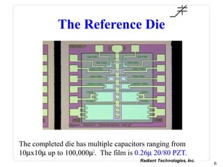
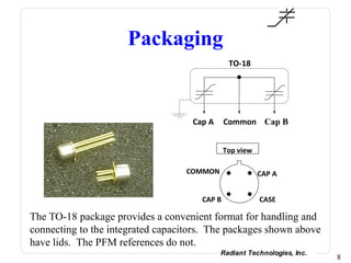
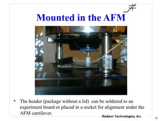
Piezoelectric
Characterization in an AFM
           Joe T. Evans, Jr,
       Radiant Technologies, Inc.


                               Radiant Technologies, Inc.
Introduction
• Radiant has developed a special packaged die containing
  thin PZT film capacitors constructed to aid piezoelectric
  characterization in an AFM.

• The capacitors have exposed top electrode and exposed
  PZT surfaces over bottom electrode to allow PFM
  characterization.

• The devices may also be used to execute more
  conventional piezoelectric measurements such as the
  butterfly loop.

• All of the characterization techniques that may be
  executed on one of these reference devices will be
  described in the following presentation.
                                        Radiant Technologies, Inc.
                                                                     2
Foundation Process
     One half of a
  micrometer of PZT,            Top       Bottom
   TiOx, & glass as                      Electrode     Ferroelectric
                             Electrode
      protection                                         material


       Half of a
  micrometer of
 Silicon Dioxide as    Silicon wafer
    a foundation


• Radiant has an established process for thin PZT film
  capacitors with platinum electrodes, top glass passivation,
  and chrome/gold metal interconnect (not shown).

                                                Radiant Technologies, Inc.
                                                                             3
20/80 PZT
                                             80

        P o la r iz a tio n (µ C /c m 2 )    70

                                             60

                                             50

                                             40

                                             30

                                             20

                                             10

                                               0

                                            -1 0


                                                   -7 .5   -5 .0   -2 .5      0 .0        2 .5   5 .0   7 .5
                                                                           V o lt a g e

• Typical hysteresis loop for Radiant 0.26µ 20/80 PZT with
  platinum electrodes.
                                                                                                 Radiant Technologies, Inc.
                                                                                                                              4
Reference Process

                         Top       Bottom
                                  Electrode     Ferroelectric
                      Electrode
                                                  material


   Silicon wafer


• The reference is fabricated without the ILD passivation
  layer to allow electrical access directly to the top
  electrode.
                                         Radiant Technologies, Inc.
                                                                      5
The Reference Die


The completed die has multiple capacitors ranging from
10µx10µ up to 100,000µ2. The film is 0.26µ 20/80 PZT.
                                      Radiant Technologies, Inc.
                                                                   6
Packaging


The die is mounted on a TO-18 transistor header without a lid. The
bottom electrode is bonded to the COMM pin. Any of the other
capacitors may be bonded to the other two free pins.
                                           Radiant Technologies, Inc.
                                                                        7
Packaging
                                               TO-18


                                    Cap A     Common Cap B


                                              Top view

                                  COMMON                 CAP A


                                      CAP B              CASE

The TO-18 package provides a convenient format for handling and
connecting to the integrated capacitors. The packages shown above
have lids. The PFM references do not.
                                            Radiant Technologies, Inc.
                                                                         8
Mounted in the AFM


• The header (package without a lid) can be soldered to an
  experiment board or placed in a socket for alignment under the
  AFM cantilever.
                                           Radiant Technologies, Inc.
                                                                        9
Electrical Connection


With a conductive cantilever tip, the PZT over the bottom electrode
without a top electrode my be scanned and poled.
                                            Radiant Technologies, Inc.
                                                                         10
PFM of Un-electroded PZT


The un-electroded PZT over bottom electrode as made exhibits the
theoretical distribution of 50:50 polarization orientation.
                                          Radiant Technologies, Inc.
                                                                       11
PFM of Un-electroded PZT


The un-electroded PZT over bottom electrode as made exhibits the
theoretical distribution of 50:50 polarization orientation.
                                          Radiant Technologies, Inc.
                                                                       12
PFM of Un-electroded PZT
Using a
conductive tip,
the exposed
PZT over
bottom
electrode can
be poled UP or
DOWN with
the application
of a bias
voltage.
In the image above, the rim outside the poled region is virgin and
was not poled in the opposite direction.
                                            Radiant Technologies, Inc.
                                                                         13
PFM of Electroded PZT


The electroded PZT may be electrically stimulated either with a
conductive tip or through one of the TO-18 package pins.
                                           Radiant Technologies, Inc.
                                                                        14
Electrical Connection
                                             TO-18
                                         Bottom electrode


                                 Cap A     Common Cap B


           PFM Stimulus Signal


The common is the bottom electrode connection. The PFM signal
can be applied to one of the capacitor top electrodes through a
package pin. In this situation, the cantilever tip provides
displacement information only.
                                               Radiant Technologies, Inc.
                                                                            15
Electrical Connection

                   TO-18
                Bottom electrode


                                         PFM Stimulus Signal
        Cap A    Common Cap B


The common is the bottom electrode connection. The PFM signal
can be applied to one of the capacitor top electrodes through a
package pin. In this situation, the cantilever tip provides
displacement information only.
                                          Radiant Technologies, Inc.
                                                                       16
PFM of Electroded PZT


Phase maps of the same region poled UP and DOWN yields
information about the presence and distribution of defects.
                                           Radiant Technologies, Inc.
                                                                        17
PFM of Switching Polarization
                                                                               80

                                                                               70

                                                                               60


                                           P o la r iz a tio n (µ C /c m 2 )
                                                                               50

                                                                               40

                                                                               30

                                                                               20

                                                                               10

                                                                                 0

                                                                               -10


                                                                                     -7 .5   -5 .0   -2 .5      0 .0        2 .5   5 .0   7 .5
                                                                                                             V o lt a g e


All of the new PFM tools may be applied to the reference.
                                           Radiant Technologies, Inc.
                                                                                                                                                 18
PFM of Switching Polarization
                      Asylum Research
                      tested a new
                      software protocol to
                      capture this movie.
                      The data took three
                      hours to collect.
                      The software
                      protocol used
                      landmark
                      recognition to
                      correct any X:Y
                      drift of the stage
                      between scans.


                   Radiant Technologies, Inc.
                                                19
Reference Applications
With its high signal-to-noise ratio, a reference may be used
for a variety of applications:

   •   Activation at less than 10 volts.
   •   Verification of equipment operation
   •   Verification of procedures
   •   Evaluating test procedures on a known-good sample
   •   Materials and polarization switching studies


                                         Radiant Technologies, Inc.
                                                                      20
Other Measurements
                     AFM Output Signal
                                                                AFM
By connecting the Z-output of an
                                                                           Conductive
AFM to a polarization tester, a large                                      Tip
array of other tests may be executed
to parallel the PFM measurements.
         Polarization Tester
                           SENSOR                                          Insulator

         DRIVE    RETURN


                                                                              Chuck


                                A wire must run directly
                                between system grounds.


                                                           Radiant Technologies, Inc.
                                                                                        21
Butterfly Loop


1.0µ PNZT with platinum electrodes, shown above, moves
approximately 15 Angstroms at 20 volts. The 0.26µ 20/80 PZT is
expected to move approximately 3 Angstroms at 9 volts.
                                         Radiant Technologies, Inc.
                                                                      22
Electrical Properties
                                                Hysteresis Parameters
                                                     50

                                                     40
        uC/cm^2, uA/cm^2, uF/cm^2


                                                     30

                                                     20

                                                     10
                                                                                       Rhyst
                                                      0
                                    -6     -4   -2         0   2        4        6     SW CV*10
                                                     -10
                                                                                       nSW CV*10
                                                     -20
                                                                                       SW IV*2.5
                                                     -30                               nSW IV*2.5

                                                     -40
                                                       Volts

• Using the AFM as a probe station, the polarization, remanent
  polarization, small signal capacitance, and leakage vs voltage
  may be measured on the same sample as are the piezoelectric
  measurements.
                                                                        Radiant Technologies, Inc.
                                                                                                     23
Conclusion
• It is now possible to measure all electrical and
  piezoelectric properties on a single capacitor.
   – Polarization hysteresis
   – Small signal capacitance hysteresis
   – Current vs Voltage
   – Butterfly loop
   – Small signal displacement
   – PFM amplitude and phase maps
   – PFM d33 loop


• Measurement and comparison of these measurements on a
  single sample will improve our understanding of the nature
  of piezoelectric materials.
                                           Radiant Technologies, Inc.
                                                                        24
Acknowledgements

An Asylum Research MFP-3D™ AFM with an Arc2™ controller
were used to capture the images in this presentation. Radiant
would like to acknowledge Asylum Research and its employees for
their assistance in this work.


                                         Radiant Technologies, Inc.
                                                                      25

Piezo Responce Force Microscopy

  • 1.
    Piezoelectric Characterization in anAFM Joe T. Evans, Jr, Radiant Technologies, Inc. Radiant Technologies, Inc.
  • 2.
    Introduction • Radiant hasdeveloped a special packaged die containing thin PZT film capacitors constructed to aid piezoelectric characterization in an AFM. • The capacitors have exposed top electrode and exposed PZT surfaces over bottom electrode to allow PFM characterization. • The devices may also be used to execute more conventional piezoelectric measurements such as the butterfly loop. • All of the characterization techniques that may be executed on one of these reference devices will be described in the following presentation. Radiant Technologies, Inc. 2
  • 3.
    Foundation Process One half of a micrometer of PZT, Top Bottom TiOx, & glass as Electrode Ferroelectric Electrode protection material Half of a micrometer of Silicon Dioxide as Silicon wafer a foundation • Radiant has an established process for thin PZT film capacitors with platinum electrodes, top glass passivation, and chrome/gold metal interconnect (not shown). Radiant Technologies, Inc. 3
  • 4.
    20/80 PZT 80 P o la r iz a tio n (µ C /c m 2 ) 70 60 50 40 30 20 10 0 -1 0 -7 .5 -5 .0 -2 .5 0 .0 2 .5 5 .0 7 .5 V o lt a g e • Typical hysteresis loop for Radiant 0.26µ 20/80 PZT with platinum electrodes. Radiant Technologies, Inc. 4
  • 5.
    Reference Process Top Bottom Electrode Ferroelectric Electrode material Silicon wafer • The reference is fabricated without the ILD passivation layer to allow electrical access directly to the top electrode. Radiant Technologies, Inc. 5
  • 6.
    The Reference Die Thecompleted die has multiple capacitors ranging from 10µx10µ up to 100,000µ2. The film is 0.26µ 20/80 PZT. Radiant Technologies, Inc. 6
  • 7.
    Packaging The die ismounted on a TO-18 transistor header without a lid. The bottom electrode is bonded to the COMM pin. Any of the other capacitors may be bonded to the other two free pins. Radiant Technologies, Inc. 7
  • 8.
    Packaging TO-18 Cap A Common Cap B Top view COMMON CAP A CAP B CASE The TO-18 package provides a convenient format for handling and connecting to the integrated capacitors. The packages shown above have lids. The PFM references do not. Radiant Technologies, Inc. 8
  • 9.
    Mounted in theAFM • The header (package without a lid) can be soldered to an experiment board or placed in a socket for alignment under the AFM cantilever. Radiant Technologies, Inc. 9
  • 10.
    Electrical Connection With aconductive cantilever tip, the PZT over the bottom electrode without a top electrode my be scanned and poled. Radiant Technologies, Inc. 10
  • 11.
    PFM of Un-electrodedPZT The un-electroded PZT over bottom electrode as made exhibits the theoretical distribution of 50:50 polarization orientation. Radiant Technologies, Inc. 11
  • 12.
    PFM of Un-electrodedPZT The un-electroded PZT over bottom electrode as made exhibits the theoretical distribution of 50:50 polarization orientation. Radiant Technologies, Inc. 12
  • 13.
    PFM of Un-electrodedPZT Using a conductive tip, the exposed PZT over bottom electrode can be poled UP or DOWN with the application of a bias voltage. In the image above, the rim outside the poled region is virgin and was not poled in the opposite direction. Radiant Technologies, Inc. 13
  • 14.
    PFM of ElectrodedPZT The electroded PZT may be electrically stimulated either with a conductive tip or through one of the TO-18 package pins. Radiant Technologies, Inc. 14
  • 15.
    Electrical Connection TO-18 Bottom electrode Cap A Common Cap B PFM Stimulus Signal The common is the bottom electrode connection. The PFM signal can be applied to one of the capacitor top electrodes through a package pin. In this situation, the cantilever tip provides displacement information only. Radiant Technologies, Inc. 15
  • 16.
    Electrical Connection TO-18 Bottom electrode PFM Stimulus Signal Cap A Common Cap B The common is the bottom electrode connection. The PFM signal can be applied to one of the capacitor top electrodes through a package pin. In this situation, the cantilever tip provides displacement information only. Radiant Technologies, Inc. 16
  • 17.
    PFM of ElectrodedPZT Phase maps of the same region poled UP and DOWN yields information about the presence and distribution of defects. Radiant Technologies, Inc. 17
  • 18.
    PFM of SwitchingPolarization 80 70 60 P o la r iz a tio n (µ C /c m 2 ) 50 40 30 20 10 0 -10 -7 .5 -5 .0 -2 .5 0 .0 2 .5 5 .0 7 .5 V o lt a g e All of the new PFM tools may be applied to the reference. Radiant Technologies, Inc. 18
  • 19.
    PFM of SwitchingPolarization Asylum Research tested a new software protocol to capture this movie. The data took three hours to collect. The software protocol used landmark recognition to correct any X:Y drift of the stage between scans. Radiant Technologies, Inc. 19
  • 20.
    Reference Applications With itshigh signal-to-noise ratio, a reference may be used for a variety of applications: • Activation at less than 10 volts. • Verification of equipment operation • Verification of procedures • Evaluating test procedures on a known-good sample • Materials and polarization switching studies Radiant Technologies, Inc. 20
  • 21.
    Other Measurements AFM Output Signal AFM By connecting the Z-output of an Conductive AFM to a polarization tester, a large Tip array of other tests may be executed to parallel the PFM measurements. Polarization Tester SENSOR Insulator DRIVE RETURN Chuck A wire must run directly between system grounds. Radiant Technologies, Inc. 21
  • 22.
    Butterfly Loop 1.0µ PNZTwith platinum electrodes, shown above, moves approximately 15 Angstroms at 20 volts. The 0.26µ 20/80 PZT is expected to move approximately 3 Angstroms at 9 volts. Radiant Technologies, Inc. 22
  • 23.
    Electrical Properties Hysteresis Parameters 50 40 uC/cm^2, uA/cm^2, uF/cm^2 30 20 10 Rhyst 0 -6 -4 -2 0 2 4 6 SW CV*10 -10 nSW CV*10 -20 SW IV*2.5 -30 nSW IV*2.5 -40 Volts • Using the AFM as a probe station, the polarization, remanent polarization, small signal capacitance, and leakage vs voltage may be measured on the same sample as are the piezoelectric measurements. Radiant Technologies, Inc. 23
  • 24.
    Conclusion • It isnow possible to measure all electrical and piezoelectric properties on a single capacitor. – Polarization hysteresis – Small signal capacitance hysteresis – Current vs Voltage – Butterfly loop – Small signal displacement – PFM amplitude and phase maps – PFM d33 loop • Measurement and comparison of these measurements on a single sample will improve our understanding of the nature of piezoelectric materials. Radiant Technologies, Inc. 24
  • 25.
    Acknowledgements An Asylum ResearchMFP-3D™ AFM with an Arc2™ controller were used to capture the images in this presentation. Radiant would like to acknowledge Asylum Research and its employees for their assistance in this work. Radiant Technologies, Inc. 25